1
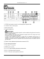
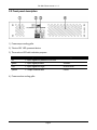
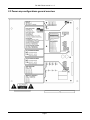
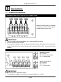
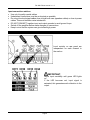
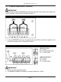
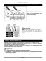
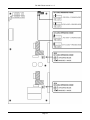
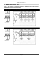
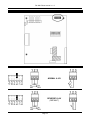
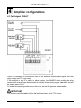
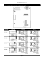
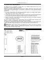
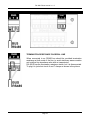
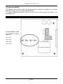
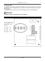
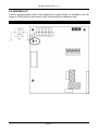
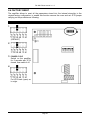
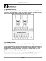
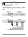
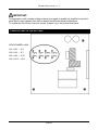
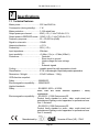
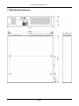
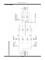
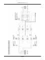
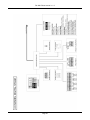
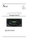
USER MANUAL Version 1.3 DA 480-R User manual v.1.3 Warranty DA 480-R is covered by 24 month warranty on its electronics parts, starting from the date of purchase. This warranty becomes void in case of tampering with the device and in case of work carried out on it by people that were not authorized by the manufacturer or by an authorized dealer. Warranty conditions are those described in the “Warranty Rules”. NOTE - responsibility of the purchaser: in case of repair under warranty, the device must be packed in order to avoid damage during transport and shipped to the manufacturer together with all the accessories. Warranty Rules. 1. In order to exercise his warranty rights, the purchaser must include with the device a copy of the evidence of purchase duly stamped by the dealer (bill/invoice). 2. The warranty lasts 24 months on the electronic parts. The warranty is granted at the point of sale or it could be directly requested to the manufacturer. 3. The warranty only covers damage to the product which makes it work badly. 4. Work under warranty will only mean repairing or replacing, free of charge, any parts acknowledged being defective during manufacture or in their material, including labour costs. 5. The warranty does not apply to damage caused by negligence or failure to comply with the instructions, or damage caused by unauthorised people, with a special reference to the external parts. 6. Also, the warranty does not apply to damage caused to the device by connection to unsuitable power sources. 7. The warranty does not cover parts that are subject to wear as a consequence of the use, as well as the chassis if the material is not defective. 8. The warranty does not include transport costs, which will be paid by the purchaser depending on way and time of transport. 9. The warranty expires 24 months after the purchase. In this case, service will be provided charging for the replaced parts, labour costs and transport according to the current rates. 10. In case of any controversy the Court of Law of Venice has the exclusive jurisdiction. Page 1 DA 480-R User manual v.1.3 SUMMARY 1. Installation 1.1 1.2 1.3 Introduction Contents of the DA 480-R Safety rules 2. Overview 2.1 2.2 2.3 Rear panel overview Front panel overview Amplifier configurations general overview 3. Connections 3.1 3.2 3.3 4 ch amplification 2 ch amplification - BRIDGED Remote volume control – VCA 4. Amplifier configurations 4.1 4.2 4.3 4.4 4.5 4.6 Failure signal - FAULT RS485 serial communication Input signal sensibility Hi-pass filter Ground-lift Factory reset 5. Protections 5.1 5.2 5.3 Speakers protection Thermal protection Over-current and short-circuit protection 6. Constant voltage outputs (100V) 6.1 Connection to the AT 480-R 7. Specifications 7.1 7.2 7.3 Technical features Mechanical dimensions Block diagram Page 2 DA 480-R User manual v.1.3 1 Installation 1.1 Introduction The power amplifier DA480-R has been developed to satisfy most of the professional audio installations and designed to provide performance with the best stability and reliability, permitting a continued use without failure and without the need of maintenance. The power stages circuitation is based on the new generation “Class D” technology that permit to obtain high quality performance, low heat dissipation and that permit to keep distortion within a very small range also with a high power supplied. Power supply circuit is “switch mode” with the benefit of high efficiency and reduced weight. 1.2 Contents of the DA 480-R Contents of the DA480-R kit: - n° 1 DA 480-R device n° 1 user manual n° 1 power supply cable 1.3 Safety rules Read carefully the following warnings to keep your and others safety, for the right use of the device and to avoid warranty invalidation. 1. Do not expose the device to rain or high humidity. Protect the device from accidental liquid penetration, if it happens, stop using the device and apply to qualified or authorized personnel. 2. Do not insert things into the device through the openings to avoid risk of fire or electric shock. 3. Before connect the amplifier, ALWAIS verify the ground connection as requested by the law. 4. Disconnect the device from the light socket before make any operation for the internal device configuration. 5. This power amplifier has been designed and produced to operate ONLY with a 230VAC mains power. 6. If the original power cord is waste or deteriorate, replace it with a similar one. 7. For speakers connections the use of cables with appropriate section and that meet the safety laws is suggested 8. Switch on the amplifier only after all the other components of the sound system have been connected and switched on, to avoid hums and annoying noise from the speakers. 9. Disconnect the device from the light socket before make cleaning operations. Clean the device with a dry and soft cloth. Do not use liquids or spray that can contain flammable elements. Page 3 DA 480-R User manual v.1.3 10. Device handling must take place only when all the cables have been disconnected. 11. Device maintenance must be done only by qualified personnel. 12. For any requirement or technical information contact InOut or authorized personnel. OBSOLETE DEVICES DISPOSAL This picture means that the device is European Directive 2002/96/EC compliant. All electronic and electric devices should be disposed separately from the normal garbage, by specific gathering plants designated by the government or by local authorities. Correct disposal of obsolete devices, of the accessories and especially of the batteries, contribute to prevent possible negative consequences on human health and on the environment. For detailed information on obsolete devices disposal, contact the municipality, the garbage disposal service or the store where you bought the device. Page 4 DA 480-R User manual v.1.3 2 Overview 2.1 Rear panel overview 1) 230VAC mains power connector, use the appropriate supplied cable. 2) Protection fuse on mains power 3) Mains power switch 4) Forced ventilation fan IMPORTANT: The power amplifier, during regular operation, needs a suitable cooling that can be done by natural or forced ventilation. Device installation must allow holes that permit a regular air flow. Air scoops are on the front panel, air exit is from the rear panel. In case of more amplifiers mounted on a single rack, air exchange could be poor; it’s advisable, in this case, to provide forced ventilation to the rack too. It’s advisable that the ventilation take place with the air aspiration from the bottom and the air emission from the top of the rack. 5) External volume adjustment potentiometers connector (VCA) 6) Fault output relay connector 7) Fault output TTL connector 8) RS485 serial connector 9) CH 1-2-3-4 input sensibility adjustment potentiometers 10) CH 1-2-3-4 balanced input connectors 11) CH 1-2-3-4 power output (speakers) connector. Page 5 DA 480-R User manual v.1.3 2.2 Front panel description 1) Power amps cooling grille. 2) “Device ON” LED, powered device. 3) Three-colour LED with indication purpose: LED Description Indicating off = input signal not present or too low green = input signal present SIGNAL red = input signal too high OVERLOAD yellow = output channel fault FAULT 4) Power section cooling grille. Page 6 DA 480-R User manual v.1.3 2.3 Power amp configurations general overview Page 7 DA 480-R User manual v.1.3 3 Connections 3.1 4 channels configuration 4 CHANNELS AMPLIFICATION OUTPUT CONNECTIONS Observe correct polarity in speaker connection to have output signals in phase with the input ones. IMPORTANT: Do not connect outputs among them or to others amplifiers outputs. Do not short circuit the outputs. To connect the speakers use the appropriate cable section depending on the connection length. Reduced section cables cause power loss along the line with, consequently, cable heating. 4 CHANNELS AMPLIFICATION INPUT CONNECTIONS BALANCED INPUT: Pin 1: ground Pin 2: reverse phase signal Pin 3: in phase signal UNBALANCED INPUT: Pin 1: ground Pin 2: ground Pin 3: in phase signal IMPORTANT: 20Kohm nominal impedance inputs. For unbalanced signals is mandatory to connect together pin 1 and 2. Page 8 DA 480-R User manual v.1.3 Input connections advices Use only hi-quality coaxial cables. Unbalanced connections must be as shortest as possible Do not put low level signal cables close to high level ones (speakers cables) or close to power cables. This avoid induction noise introduction. DO NOT CONNECT together input and output grounds to avoid ground loops. Switch off the amplifier before make changes on connections. Keep in mind that the system can give instant high power. 4 CHANNEL AMPLIFICATION INPUT LEVEL ADJUSTMENT Level controls on rear panel are independent for each channel in the section. IMPORTANT: Adjust input sensibility until green LED lights on. If the LED becomes red, input signal is saturated; this generates audio distortion to the output. Page 9 DA 480-R User manual v.1.3 3.2 2 channels amplification - BRIDGED IMPORTANT: When a section is used in BRIDGED mode (the two channels of the section are bridged), the internal “jumpers” must be set as indicated on page 12. 2 CHANNELS BRIDGED MODE AMPLIFICATION OUTPUT CONNECTION In case of BRIDGED mode use, the outputs are ground lifted, also with no signal; do not connect the negative pole to the amplifier chassis. 2 CHANNELS BRIDGED MODE AMPLIFICATION INPUT CONNECTION BALANCED INPUT: Pin 1: ground Pin 2: reversed phase signal Pin 3: in phase signal UNBALANCED INPUT: Pin 1: ground Pin 2: ground Pin 3: in phase signal IMPORTANT: 20Kohm nominal impedance inputs. For unbalanced signals is mandatory to connect together pin 1 and 2. Page 10 DA 480-R User manual v.1.3 2 CHANNELS BRIDGED MODE AMPLIFICATION INPUT LEVELS ADJUSTMENT Volume adjustment for the section is made by the correspondent input channel potentiometer. IMPORTANT: Adjust input sensibility until green LED lights on. If the LED becomes red, input signal is saturated; this generates audio distortion to the output. STANDARD - BRIDGED MODE SETTING DA480-R has 4 independent channels divided into 2 sections CH1-CH2 and CH3-CH4. Such sections run in separate and independent channels mode, or in “BRIDGED” mode that means that the same section channels are bridged. Operating mode is set by “jumpers” that are into the amplifier (TWO for each section), that can be reached removing the 4 cover screws. IMPORTANT: In such configuration 8 ohms is the minimum impedance It’s advisable to disconnect mains cable during mode setting operations to avoid damage to the amplifier. Page 11 DA 480-R User manual v.1.3 Page 12 DA 480-R User manual v.1.3 3.3 Volume remote control - VCA There is one connector for each single channel on the amplifier back, where connect a potentiometer to allow volume remote control. VOLUME REMOTE CONTROL IN 4 CHANNELS AMPLIFICATION 20 / 50 KΩ LINEAR POT. VOLUME REMOTE CONTROL IN 2 CHANNELS BRIDGED MODE AMPLIFICATION 20 / 50 KΩ LINEAR POT. Page 13 DA 480-R User manual v.1.3 REMOTE CONTROL INTERNAL CONFIGURATION JUMPER VCA MUTE NORMAL 0-10V REVERSE 10-0V (DEFAULT) Page 14 DA 480-R User manual v.1.3 4 Amplifier configurations 4.1 Fault signal - FAULT There is a connector on the amplifier back for the amplified channels fault signal, both with relay contact and TTL logic output. If the amplifier is part of a safety or alarm system, the DA480-R allows setting the relay contacts with reverse logic where contact is normally closed during regular operations and will be open in case of fault. To enable this operating mode remove the cover and set the jumpers as hereinafter. IMPORTANT: This function could be enabled only for the fault signal relay, not for TTL outputs. Page 15 DA 480-R User manual v.1.3 FAULT SIGNAL RELAY OUTPUT INTERNAL SETTING CHANNEL JUMPER NORMAL CH1/CH2 CH1/CH2 CH3/CH4 CH3/CH4 Page 16 FAULT DA 480-R User manual v.1.3 4.2 RS485 Serial communication DA 480-R could be connected via serial port to an RS485 communication bus, to be controlled by a master system or a computer. Because of disturbs on the serial line coming from outside, dysfunctions can occur to the master system with possible harms to the amplifier; to avoid such troubles use the following precautions: Do not put serial cables in the same pipe with power cables or hi-voltage cables. Keep a safe distance from those cables, at least 10 cm. Connect the cable screen to the ground at one end (not both ends); ground connection should not be made in the same point where hi-voltage circuits are connected to the ground. Switch off the whole system before start wiring the serial lines: also missing or parasite currents could damage the modules. DA 480-R support multipoint serial communication with the RS-485 electric standard, that allows to connect up to 32 amplifiers, each one with its own address. The address is a number that enables the master system to establish the communication with a specific DA-480 among the several ones connected to the same communication bus. IMPORTANT: during address setting pay attention to not define more than one module with the same number, otherwise communication becomes confuse and irregular and exchanged data will doesn’t make sense. ADDRESS SETTING ON RS485 BUS Page 17 DA 480-R User manual v.1.3 RS485 BUS CONNECTION TERMINATION RESISTANCE ON SERIAL LINE When connected to an RS485 bus should be provided termination resistance at both ends of the line, to avoid stationary waves creation ant to define line impedance also with no transmission. DA 480-R has the termination resistance inside, but it is disconnected. To plug it in just short circuit A and T clamps as shown in the picture. Page 18 DA 480-R User manual v.1.3 4.3 Input sensibility The amplifier has a circuit inside that allows selecting a different sensibility for the audio signal incoming to accept low output signal sources. To enable a different sensibility remove the cover and set the jumpers as shown in the following picture. INPUT SIGNAL SENSIBILITY SETTING WITHOUTJUMPER= -5,7dBu WITH JUMPER =+3,8dBu (DEFAULT) CH1 = JP1 CH2 = JP5 CH3 = JP8 CH4 = JP11 Page 19 DA 480-R User manual v.1.3 4.4 Hi-pass filter The amplifier has inside an hi-pass filter between the input signal section and the power amplification section, independent for each channel; this allow to directly drive the limited band speakers. To enable the filter remove the cover and set the jumpers as per the following scheme. IMPORTANT: To enable the filter use both jumpers for each channel. HI-PASS FILTER SETTING WITHOUTJUMPER= 160Hz WITH JUMPER = 30Hz (DEFAULT) CH1 = JP2 – JP3 CH2 = JP6 – JP7 CH3 = JP9 – JP10 CH4 = JP12 – JP13 Page 20 DA 480-R User manual v.1.3 4.5 GROUND-LIFT If there is low frequencies noise on the speakers due to ground loops, it’s advisable to set JP4 jumper to OPEN position; that means to split audio ground from chassis ground. GROUND LIFT CONFIGURATION Page 21 DA 480-R User manual v.1.3 4.6 FACTORY RESET The amplifier allows to reset all the parameters stored into the internal microchip to the original factory configuration; to enable this function remove the cover and set JP19 jumper carrying out the procedure as following: FACTORY RESET 1 (DEFAULT) 2 3 POWER CYCLE Switch on the amplifier for 5 seconds with JP19 closed, than switch it off. 4 Put JP19 back (open) as in origin. Page 22 DA 480-R User manual v.1.3 5 Protections 5.1 Speakers protection DA 480-R ha an output protection relay that disconnect speakers in case of amplifier fault. During boot the device makes a voltage test, checks the optimal working of the power amplifiers and, only after, speakers connector relay will be enabled. 5.2 Thermal protection When the amplifier’s internal temperature reaches high levels, the cooling fan will be activated with variable speed depending on the temperature. In case the amplifiers reach the maximum allowed temperature, the thermal protection will be activated and the involved channels will be deactivated, switching them back on when an acceptable running temperature is reached. This condition is indicated with a FAULT LED. 5.3 Over-current and short-circuit protection The device has inside an “high-currents” or “output short-circuit present” protection circuit, in those cases the involved channels will be switched off with FAULT LED indication. Page 23 DA 480-R User manual v.1.3 6 Constant voltage outputs (100V) 6. 1 Connection to the AT 480-R For applications with constant voltage outputs, DA 480-R can be connected to the AT480-R, a multi-channel audio transformer that assure a high passing band, low distortion and complete galvanic insulation between audio source and the 100V speaker lines. To connect the AT 480R to the DA 480-R, use the cables, included in the package, as following: Page 24 DA 480-R User manual v.1.3 IMPORTANT: For applications with constant voltage outputs we suggest to enable the amplifier’s internal hipass filter for each channel, this allow to directly drive limited band loudspeakers. To enable the filter lift the cover and set the “jumpers” as in the picture here below. AT 480-R HI-PASS FILTER SETTINGS WITHOUTJUMPER= 160Hz CH1 = JP2 – JP3 CH2 = JP6 – JP7 CH3 = JP9 – JP10 CH4 = JP12 – JP13 Page 25 DA 480-R User manual v.1.3 7 Specifications 7.1 Technical features Mains power……………………..… : 230 Vac 50/60 Hz Consumption (during standby)….. : 1 W Mains protection………………..…. : 3,15A retard fuse. Output power per channel……….. : 80W ( 4 Ω ) 1 kHz THD+N= 0,1% Output power in BRIDGED mode.. : 160W ( 8 Ω ) 1 kHz THD+N= 0,1% Frequency response…………..….. : 20 ~ 20.000 Hz (±3dB) Signal to noise ratio……………..... : 102dB. Harmonic distortion………..……... : < 0,1% Productivity………………………… : 90% ( 4 Ω ) Input impedance………………..…. : 20kohms Input sensibility………………….... : +3,8dbu (1,2v) e –5,7dbu (400mV) Protections………….………………- Overload - Short circuit to ground - Under-voltage and over-voltage - DC - Subsonic signals Cooling………………………..……. : variable speed fan with temperature check Classification………………..…….. : IP 30 in the strength of liquid and powders permeation. Dimensions / Weight……..………. : 215x211x44mm. / 1,8Kg. CEE directive compliant: Safety……………..….........…….. : 2006/95/EC Electromagnetic compatibility..... : 2004/108/EC Applied standards: Safety..........................................: EN 60065: 2002 + A1:2006 Audio, video and similar electronic apparatus – Safety requirements. Electromagnetic compatibility..... : EN 55103-1: 1998 Environment E2 Product family standard or audio, video, audio-visual and entertainment lighting control apparatus for professional use. Part 1: Emission : EN 55103-2: 1998 Environment E2 Product family standard or audio, video, audio-visual and entertainment lighting control apparatus for professional use. Part 2: Immunity Manufactured by: Noventa di Piave (VE) - ITALY Page 26 DA 480-R User manual v.1.3 7.2 Mechanical dimensions Page 27 DA 480-R User manual v.1.3 7.3 Block diagram Page 28 DA 480-R User manual v.1.3 Page 29 DA 480-R User manual v.1.3 Page 30