1
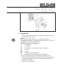
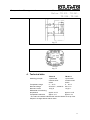
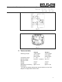
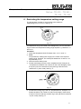
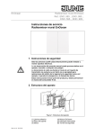
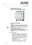
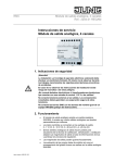
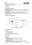
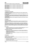
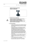
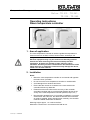
Temperature Management
Room temperature controller
Ref.-no.: TR..231.., TR..241..,
TR..236.., TR..246..
Operating Instructions
Room temperature controller
1. Area of application
The room temperature controller is used to regulate the temperature in
closed rooms such as flats, schools, function suites, workshops, etc.
Safety instructions
Electrical equipment may only be installed and fitted by qualified
electricians while observing the current accident prevention
regulations. A relative air humidity of max. 95% may not be
exceeded. Avoid any moisture condensation. Non-observance of the
safety warnings or installation instructions may damage the device,
cause a fire or other hazards.
2. Installation
Notes:
•
Mount the room temperature controller on an internal wall opposite
the heat source if possible.
•
Do not mount the room temperature controller on outside walls.
•
Avoid draughts from windows and doors.
•
Ensure that the normal air circulation in the room reaches the
controller without any obstacles.
•
External heat sources influence the accuracy of the controller.
Avoid direct sunlight and do not place heat-emitting devices in the
vicinity of the room temperature controller (heaters, lamps, etc.).
•
Dimmers also generate heat. If a controller is installed in a common
switch frame with a dimmer, the distance between them should be
as great as possible. When arranging them vertically, the controller
must be installed underneath the dimmer.
Mounting height: approx. 1.5 m above the floor.
Mounted in a switch box in accordance with DIN 49 073.
Stand: Sep-11 24091002
Temperature Management
Room temperature controller
Ref.-no.: TR..231.., TR..241..,
TR..236.., TR..246..
Fig. c
3. Connection
1. Carry out the electrical connection according to the respective wiring
diagram (Fig. (2) or Fig. (3).
Note:
Ensure that the neutral conductor N is connected to terminal N.
Considerable fluctuations in temperature may otherwise occur. Conductor
cross-section: 1 to 2.5 mm2 solid conductor.
Symbols used in the wiring diagram:
L
= L conductor
N
= N- conductor
= Connection for clock signal to reduce temperature
= Heating
RF
TA
= Cooling
= Resistor for thermal feedback
= Resistor for night reduction of room temperature
2. Clip the rocker (A in Fig. c) on the switch in the flush insert.
3. Place the center plate together with the frame on the flush insert. The
center plate must snap in place in the top left of the housing base.
4. Tighten the screw (B).
5. Clip on the setting knob (C).
2
Temperature Management
Room temperature controller
Ref.-no.: TR..231.., TR..241..,
TR..236.., TR..246..
Fig. 2
Fig. 2
4. Technical data
Switching principle
TR 231 U
1-pole break
contact+on/off
switch
5 ... 30 °C
AC 230 V ~, 50/60 Hz
10 (4) A
TR 241 U
1-pole break
contact+on/off
switch
5 ... 30 °C
AC 24 V ~
10 (4) A
Temperature range
Nominal voltage
Nominal current*
Differential of functioning
temperature
approx. 0.5 K
approx. 0.5 K
Temperature reduction
approx. 4 K
approx. 4 K
* The value in brackets indicates the inductive load at a cos φ of 0.6.
Subject to change without further notice.
3
Temperature Management
Room temperature controller
Ref.-no.: TR..231.., TR..241..,
TR..236.., TR..246..
Fig. 3
Fig. 3
5. Technical data
Switching principle
TR 236 U
1-pole change
over contact
without switch
5 … 30°C
AC 230 V ~, 50/60 Hz
TR 246 U
1-pole changeover contact
without switch
5 ... 30 °C
AC 24 V ~
Temperature range
Nominal voltage
Nominal current*
Heating
10 (4) A
10 (4) A
Cooling
5 (2) A
5 (2) A
Differential of functioning approx. 0.5 K
approx. 0.5 K
temperature
* The value in brackets indicates the inductive load at a cos φ of 0.6.
Subject to change without further notice.
4
Temperature Management
Room temperature controller
Ref.-no.: TR..231.., TR..241..,
TR..236.., TR..246..
6. Restricting the temperature setting range
The temperature controller is set ex works to the maximum
setting range of 5 °C to 30 °C. See Fig. f.
Fig. f
Two adjustment rings are located in the setting knob. You can use these
rings to restrict the temperature setting range required e.g. between 8 °C
and 23 °C.
Procedure:
1. Select the temperature limits. Example: max. 23 °C, min 8 °C
2. Note!
First position the setting knob roughly in the centre of the required
setting range. Example: The centre point between 8 °C and 23 °C is
approximately 15 °C.
3. Now remove the setting knob.
4. Set the red locating ring to the max. temperature limit. Example: 23
°C Rotate anti-clockwise. The numbers on the outer dial apply! Insert
the tip of a pen in the hole and turn the red ring to the left until it
reaches 23 °C (max. scale). See Fig. g.
Fig. g
5. Set the blue locating ring to the min. temperature limit. Example: 8 °C
Rotate clockwise. The numbers on the inner dial apply. Insert the tip
of a pen in the hole and turn the blue ring to the right until it reaches 8
°C (min. scale). See Fig. h
5
Temperature Management
Room temperature controller
Ref.-no.: TR..231.., TR..241..,
TR..236.., TR..246..
Fig. h
6. Clip on the setting knob. The pointer must be roughly in the centre of
the new setting range (see point 2). Example: approx. 15 °C
Scale for setting the temperature with dials
1 = approx. 05°C
2 = approx. 10°C
3 = approx. 15°C
4 = approx. 20°C
5 = approx. 25°C
6 = approx. 30°C
7. Symbols
Off
I On
8. Guarantee
Our products are under guarantee within the scope of the statutory
provisions.
Please return the unit postage paid to our central service
department giving a brief description of the fault:
ALBRECHT JUNG GMBH & CO. KG
Service-Center
Kupferstr. 17-19
D-44532 Lünen
Service-Line: 0 23 55 . 80 65 51
Telefax:
0 23 55 . 80 61 89
E-Mail:
[email protected]
General equipment
Service-Line: 0 23 55 . 80 65 55
Telefax:
0 23 55 . 80 62 55
E-Mail:
[email protected]
KNX equipment
Service-Line: 0 23 55 . 80 65 56
Telefax:
0 23 55 . 80 62 55
E-Mail:
[email protected]
6