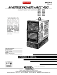
1
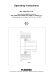
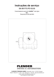
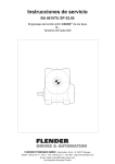
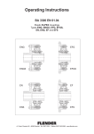
Operating Instructions
BA 2310 EN 05.04
Three-phase and
Single-phase alternating current motor
and brake motors
with accessories
FLENDER TÜBINGEN GMBH ⋅ Bahnhofstr. 40-44 ⋅ D-72072 Tübingen
Telefon +49 (0) 70 71 - 707 0 ⋅ Fax +49 (0) 70 71 - 707 400 ⋅ http://www.flender.com
E-mail: [email protected]
A company of the Flender group
Contents
1.
Important instructions
5
1.1
1.2
1.3
Instruction symbols in the operating instructions
General instructions
Amendments
5
5
6
2.
Safety instructions
7
2.1
2.2
Intended use
General safety instructions
7
7
3.
Technical data
8
3.1
3.2
3.3
Type designations
General technical data
Weights
8
10
10
4.
Technical description
11
4.1
4.2
4.3
4.4
4.5
4.6
4.7
4.8
4.9
4.10
4.10.1
4.10.2
4.10.3
General description
Shaft bearing
Surface cooling
Motor housing
Stator winding
Rotor
Terminal boxes
Monitoring equipment (special version)
Rating plates
Paint coats
General
Painted version
Primed version
11
11
11
11
11
11
12
12
12
13
13
13
14
5.
Incoming goods, Handling and Storage
15
5.1
5.2
5.3
5.3.1
5.3.2
Incoming goods
Handling
Storage
Storage up to 2 years
Storage under special conditions
15
15
17
17
18
6.
Installation
19
6.1
6.2
6.3
6.4
6.5
6.6
6.6.1
6.6.2
6.6.3
General information on installation
Place and conditions of installation
Condensation drain holes
Drives with foot mounting
Installation of input drive and output drive elements on gear unit shafts
Electrical connection
Connection, insulation resistance
Direction of rotation and terminal designation
Additional equipment (special version)
19
19
20
20
20
21
21
21
22
7.
Start-up
23
8.
Operation
23
9.
Faults, causes and remedy
24
BA 2310 EN 05.04
3 / 54
10.
Maintenance and repair
25
10.1
10.2
10.2.1
10.2.2
10.2.3
10.3
10.3.1
10.3.2
10.4
10.4.1
10.4.2
10.4.3
10.4.4
General information for maintenance
Description of maintenance and repair work
Clean drive
Checking tightness of fastening bolts
Inspection of the drive
Lubrication
Grease service lives
Lubricants
Single-disk spring-actuated brake
Key data for braking torque adjustment and readjusting the air gap
Braking torque adjustment
Readjusting air gap
Replace rotor
25
25
25
26
26
26
27
28
29
30
31
32
32
11.
Disposal
33
12.
Stocking spare parts and customer service addresses
34
12.1
12.2
12.2.1
12.2.1.1
12.2.1.2
12.2.1.3
12.2.1.4
12.2.1.5
12.2.2
12.2.2.1
12.2.2.2
12.2.2.3
12.2.2.4
12.2.3
12.2.4
12.3
Stocking spare parts
Spare parts lists
Motors
MODULOG ®-Motor Sizes 71 - 200
Motors M1, G80, A90, A100, A112
Motors G132, G160, G180, G200
IEC-Motor Sizes 71 - 200
Description of components
Brake motors
MODULOG ® Brake motor Sizes 71 - 200
Brake motors M1, G80, A90, A100, A112
Brake motors G132, G160, G180, G200
Description of components
Pulse generator
Ventilation
Customer-service addresses
FLENDER TÜBINGEN GMBH Germany
FLENDER TÜBINGEN GMBH Europe
FLENDER TÜBINGEN GMBH International
34
35
35
35
36
37
38
39
40
40
41
42
43
44
48
50
50
51
52
13.
Declaration by the manufacturer
54
13.1
Declaration by the manufacturer
54
BA 2310 EN 05.04
4 / 54
1.
Important instructions
1.1
Instruction symbols in the operating instructions
Instructions relating to operating safety are emphasized as follows:
Danger.
Possible consequences: Death or very severe injuries.
Caution.
Possible consequences: Damage to the drive and the environment.
Note.
Pointers for application and useful information.
1.2
General instructions
These operating instructions are an integral part of the motor delivery.
These operating instructions apply to the standard version of the motors up to size 200 for the
MOTOX®-N gear-unit series.
Note.
Special types of motors and their additional equipment are governed by these
operating instructions, the special contractual agreements and technical documents.
Observe further operating instructions supplied for gear units, couplings, additional
fittings, etc.
Note.
We accept no responsibility for damage or disruption resulting from disregard of these
operating instructions.
Keep these operating instructions in the vicinity of the motor.
Read these operating instructions before working with the drive.
Only a precise knowledge of these operating instructions will guarantee reliable, faultfree operation of
the drive by avoiding operating errors and improper use.
The drives described in these Instructions reflect the state of technical development at the time these
instructions went to print.
In the interest of technical progress we reserve the right to make changes to the individual assemblies
and accessories which we regard as necessary to preserve their essential characteristics and improve
the efficiency and safety of the drive.
BA 2310 EN 05.04
5 / 54
The copyright to these operating instructions is held by FLENDER TÜBINGEN GMBH.
These operating instructions must not be wholly or partly reproduced, used in any unauthorised way
for competitive purposes or made available to third parties without our agreement.
Amendments or additions to these operating instructions may be made only by us; otherwise any
guarantee claim against us will lapse.
Technical enquiries should be addressed to the following works
FLENDER TÜBINGEN GMBH
Postfach 1709 ⋅ D-72007 Tübingen
Bahnhofstr. 40-44 ⋅ D-72072 Tübingen
Telefon +49 (0) 70 71 - 707 0
Fax +49 (0) 70 71 - 707 400
E-mail: [email protected]
http://www.flender.com
24 h Service Hotline +49 (0) 172 - 7 32 29 55
or to one of our customer-services. The addresses of the customer-services are given in section 12.
“Stocking spare parts and customer service addresses“.
1.3
Amendments
These operating instruction replace the operating instructions BA M295.
BA 2310 EN 05.04
6 / 54
2.
Safety instructions
2.1
Intended use
The low-voltage machines described in these operating instructions have been developed for stationary
use in general engineering applications. Unless otherwise agreed, the drives have been designed for
use in plant and equipment in industral environments.
They comply with the harmonised standards of the EN 60034 (VDE 0530) series. Use in an explosive
environment is prohibited.
The drives have been manufactured in accordance with the state of the art and are delivered in a
condition for safe and reliable use. Any changes on the part of the user which may affect safety and
reliability are prohibited.
The drives are designed only for the application described in section 3. “Technical data“. They must not
be operated outside the specified power limits. Other operating conditions must be contractually
agreed.
Protection types v P54 must not be used out of doors. Air-cooled versions are designed for ambient
temperatures of –20 °C to +40 °C and installation altitudes of v 1 000 m above mean sea level. Please
note deviating specifications on the rating plate. The conditions at the place of use must comply with
all the specifications on the rating plate.
Note.
Low-voltage machines are components for installation in machines as defined in the
98/37/EC machinery guideline. Start-up is not permitted until it has been ascertained
that the end product complies with this guideline.
2.2
General safety instructions
Low-voltage machines have dangerous, live and rotating parts and possibly hot surfaces.
Incorrect behaviour may cause damage and personal injury.
The drives must be installed, started up, operated, maintained and, if necessary, repaired only by
authorised, properly trained and qualified personnel. For definition of expert staff, refer to i.a. IEC 364,
EN 50110-1/VDE 0105.
The operator must ensure that all persons involved in installation, operation, maintenance and repair
have read and understood these operating instructions and comply with them at all times in order to:
- avoid injury or damage
- ensure the safety and reliability of the drive
- avoid disruptions and environmental damage through incorrect use.
Carry out work on the drives only when they are at a standstill.
Secure the drive units against unintentional starting (e.g. lock key switches or remove fuses in the power
supply).
A notice should be attached to the start switch stating clearly that work on the drives is in progress.
Carry out all work with great care and with due regard to safety.
Always observe the instructions on the plates on the drives. The plates must be kept free from paint
and dirt at all times. Replace any missing plates.
Ensure compliance with the relevant safety and environmental regulations during transport, assembly
and dismantling, operation, and care and maintenance of the unit.
Secure rotating drive parts, e.g. couplings, gears or belt drives, against contact by means of suitable
safety devices.
When installing the drives in plant or equipment, the manufacturer of such plant or equipment must
ensure that the contents of the present operating instructions are incorporated in his own instructions,
information and descriptions.
BA 2310 EN 05.04
7 / 54
3.
Technical data
3.1
Type designations
Example:
M
160
L
B
12/2
R
-
L
MM
400
GH
-
IM
Motor type
Size
Construction length
Letter of performance
value
Number of poles
Additional features
Brake type
Microswitch
Rated braking torque
Brake type
Transmitter system
Motor type
A Three-phase motor, A-series
AB Single-phase motor, A-series, with phase-shifting capacitor
AK Single-phase motor, A-series, with phase-shifting capacitor, starting capacitor and
starting relay
G Three-phase motor, G-series
GB Single-phase motor, G-series, with phase-shifting capacitor
GK Single-phase motor, G-series, with phase-shifting capacitor, starting capacitor and
starting relay
M Three-phase motor, M1- and M2-series
M Three-phase motor, MODULOG-series
MB Single-phase motor, M1- and M2-series, with phase-shifting capacitor
MI Three-phase motor, IEC MODULOG-series
MK Single-phase motor, M1- and M2-series, with phase-shifting capacitor, starting capacitor and
starting relay
Q Three-phase motor, special version
QB Single-phase motor, special version, with phase-shifting capacitor
QK Single-phase motor, special version, with phase-shifting capacitor, starting capacitor and
starting relay
R Three-phase motor, R-series
RB Single-phase motor, R-series, with phase-shifting capacitor
RK Single-phase motor, R-series, with phase-shifting capacitor, starting capacitor and
starting relay
BA 2310 EN 05.04
8 / 54
Size
1
2
56
63
71
80
90S/L
100L
112M
132S/M
160M/L
180M/L
200L
Number of poles
2
2-pole
4
4-pole
6
6-pole
8
8-pole
4/2 4/2-pole
6/2 6/2-pole
6/4 6/4-pole
8/2 8/2-pole
8/4 8/4-pole
8/6 8/6-pole
12/2 12/2-pole
Additional features
E
Efficiency class EFF1
F
Forced ventilation
H
Low noise level
I
Flywheel ventilator
Q
Modified rotor
R
Silumine rotor
U
Not ventilated
W
Protective cover
X
Backstop
Construction length
S short construction length
M medium construction length
L long construction length
Letter of performance value
A
B
C
D
E
F
G
H
I
K
L
P
Brake type
A
Working-current-operated
B
Direct current, closed-current-operated, B-Type
D
Three-phase current
E
Alternating current
F
Direct current, closed-current-operated, F-Type
G
Direct current, closed-current-operated, G-Type
L
Direct current, closed-current-operated, L-Type
P
Direct current, closed-current-operated, P-Type
T
Direct current, Tandem
Microswitch
M one microswitch for monitoring the air gap or wear
MM one microswitch for monitoring the air gap and one for monitoring wear
Rated braking torque
A-Type30; 60; 120; 240; 480
B-Type7,5; 15; 35; 75
D-Type7,5; 15; 35; 75
E-Type 1
G-Type7,5; 15; 35; 75
L-Type 4; 8; 16; 32; 60; 80; 150; 240; 360
P-Type 4; 8; 16
T-Type 8/8; 16/16; 28/28; 50/50; 100/100; 150/150; 250/250; 400/400
Brake type
G enclosed
GH enclosed with manual lifting
N Standard version
NH Standard design with manual lifting
Transmitter system
IM Pulse generator
IN
Incremental transmitter
RE Resolver
TA Tachogenerator
BA 2310 EN 05.04
9 / 54
3.2
General technical data
The most important technical data are shown on the rating plate of the gear units of gear motors.
These data together with the contractual agreements on the drive units determine the limits of its proper
use.
In the case of gear motors a rating plate attached to the motor serves for the entire drive.
In certain cases separate rating plates are attached to the gear unit and the motor.
Examples: Rating plate - gear motor
13
1
4
5
14
18
20
22
6
7
26
12
15
8
16
19
21
23
9
3
17
11
2
24
10
25
Figure 3.2: Rating plate
1
2
3
4
5
6
7
8
9
10
11
12
13
Company logo
Manufacturing date encoded
Weight m [kg]
Order no. / seq. no.
Model - Type - Size
Mounting position
Speed n2 [min–1]
Type of oil
Oil viscosity
ISO VG class to DIN 51519 / ISO 3448
Oil quantity [l] Main gear unit /
ancillary transmission+extruder flange
Free space for additional data
max. ambient temperature TUmax [°C]
Phase number and type of current of the motor
14 Switch symbols to
DIN EN 60617 T6 / IEC 617-6
15 Rating voltage U [V]
16 Rating current Ι [A]
17 Rating frequency f [Hz]
18 Rating speed n [min–1]
19 Rating performance P [kW]
20 Operating mode (if 0 S1)
21 Performance factor cos ϕ
24 Type of protection to IEC 60034-5 or IEC 529
23 Heat class Th. Cl.
24 applied standard
25 CE-marking or other marking, if any
26 Brake data
For further technical data, please refer to the drawings in the documentation.
3.3
Weights
The weight of the overall drive including motor is indicated on the rating plate of the gear unit or gear
motor, if it exceeds 30 kg; in each case it is shown in the delivery documents.
Where there are several rating plates on one drive, the specification on the main gear unit is decisive.
The weight specification refers only to the condition on delivery of the products.
BA 2310 EN 05.04
10 / 54
4.
Technical description
4.1
General description
Assembly option to EN 60034-7.
Add-on dimensions with surface cooling up to size 200L to
- to Works standard of FLENDER TÜBINGEN GMBH in the modular system
- to IEC 60072 for the assembly options IM B5 and IM B14.
Connection drawings to DIN VDE 0530-8, IEC 60034-8.
Type of protection to EN 60034-5.
Type of cooling to EN 60034-6. IC 411 surface cooling.
For details of the design of the motors, please refer to the relevant catalogues.
4.2
Shaft bearing
The motors are fitted with grease-lubricated rolling bearings. The bearings on standard-design
surface-cooled motors up to size 200 are life-lubricated.For normal coolant temperatures the bearings
are filled at the factory with grease which under normal operating conditions need not be renewed for
several years.
4.3
Surface cooling
Layout for rib-cooling, where an external ventilator draws in cooling air through holes in the ventilator
cover and expels it over the surface of the stator housing.
4.4
Motor housing
The stator housing and the bearing end plates are of aluminium alloy or grey cast iron, depending on
the size. The ventilator cover is made from steel sheet. Stator housing surface with cooling ribs and
add-on terminal box.
4.5
Stator winding
The stator winding is designed in heat class (see rating plate) to EN 60034-1. High-quality varnished
wires, suitable surface insulation materials and the type of impregnation guarantee high mechanical
and electrical strength, combined with a high utility value and long service life.
If required, the winding heads are cast with silicon rubber. Particular advantages are offered by the use
of sealing in combination with heat classes F and H, if motors are used in especially difficult starting
and braking conditions. The sealing also enables a higher mechanical resistance to short-circuiting of
the winding and the motor (in the case of surface cooling) to be protected internally against
condensation.
4.6
Rotor
On the smaller motors the rotor has a squirrel cage of die-cast aluminium, on the larger ones and for
operation in special starting and braking conditions a cage in hard-soldered construction. The rotor is
dynamically balanced.
The balancing condition is specified in the parallel keyway.
The motors in standard design comply with vibration severity level N to DIN VDE 0530-14 /
IEC 60034-14, in special cases level R (reduced) or S (special).
BA 2310 EN 05.04
11 / 54
4.7
Terminal boxes
Provided in motor terminal box are, if required, additional connection terminals for monitoring
equipment as well as the motor connection terminals (terminal board, terminal block, etc.).
On special request an additional terminal box is added to the larger motors.
The number of available terminals is shown on the circuit diagrams located in the terminal box.
4.8
Monitoring equipment (special version)
Monitoring equipment is provided only on special request.
The technical data are shown on the circuit diagrams, the rating plates or documents relating
specifically to the order.
4.9
Rating plates
The rating plates of the gear motors are normally of coated aluminium foil. They are covered with a
special masking film which guarantees permanent resistance to UV radiation and media of all kinds
(oils, greases, salt water, cleaning agents, etc.).
The adhesives and materials are selected to ensure extremely firm adhesion and permanent high
legibility, even at the limits of the range of operating temperatures (–40 °C ... +155 °C).
The edges of the rating plates are coated with a matching special paint, see section 4.10 “Paint coats“.
In special cases, i.e. special specifications, riveted or bolted metal plates are used.
BA 2310 EN 05.04
12 / 54
4.10
Paint coats
4.10.1
General
All paint finishes are sprayed on.
Note.
Information on repaintability is not a guarantee of the quality of the paint material
supplied by your supplier.
Only the paint manufacturer is liable for the quality and compatibility.
4.10.2
Painted version
Paint system
Colours
Typical area of
application
Plastic
2K-PUR
RAL 1007, 1012, 1023,
2000, 2004, 3000, 5007,
RAL 1003, 1018, 2004,
5009, 5010, 5012, 5015,
5002, 5015, 6011, 7000,
6011, 7001, 7011, 7030,
7031, 9010, 9011, 9016
7032, 7035, 9005, 9006,
black-mat
Standard-1-layer paint
finish for interior areas
2K-epoxide
RAL 5015, 6018,
7031, 7035
high-quality paint
Standard 2-layer paint
finish in the outside
finish, especially for
area or where
outside installation or
exposed to dilute acid
higher corrosion
and alkaline
protection requirements
solution (v 5 %)
Repaintability
after prior rubbing down after prior rubbing down
with: Plastic or synthetic
with: 2K-PUR paint,
resin paint
2K-epoxide paint
after prior rubbing
down with: 2K-PUR
paint, 2K-epoxide
paint, 2K-AC paint
Chem. phys.
resistance
good resistance to:
cleaning agent, oil and
petrol; resistant to:
exposure to dilute acid
and alkaline solution for
a short time (v 3 %);
not solvent-resistant;
not steam-resistant
very good resistance to:
oil, grease, petrol,
water, seawater and
cleaning agent; good
resistance to: weather
action and dilute acid
and alkaline solution
(v 3 %); good
mechanical resistance
to: abrasion
excellent resistance
to: weak acid and
alkaline solution
(v 5 %), oil, grease,
petrol, cooling
emulsion, salt,
solvent; tough and
scratchproof
paint film
Temperature
resistance
–40 °C ... +100 °C
temporarily up to 140 °C
–40 °C ... +150 °C
–40 °C ... +150 °C
Remark
Standard paint finish for
Standard paint finish
cooling tower and
with very good adhesive
agitator drives or, if
property, not suitable
requested, resistance to
for: storage or
sea water below deck,
installation outside
etc.
Table 4.10.2: Painted version
BA 2310 EN 05.04
13 / 54
2K-epoxide paint
becomes chalky
when installed
outside (without
effect on quality),
high gloss with good
mechanical
resistance
4.10.3
Primed version
Paint system
primed
unpainted
RAL 7032
-
Typical area of application
for repainting*): adhesion
promoter for all common paint
systems, temporary corrosion
prevention
for repainting*): temporary
corrosion prevention
Repaintability
very good with: plastic paint,
synthetic resin paint, 2K-PUR
paint, 2K-epoxide paint, SH
paint, 2K-AC paint
very good with: Plastic paint,
synthetic resin paint, oil paint,
bitumen paint, 2K-PUR paint,
2K-epoxide paint
Chem. phys. resistance
good resistance to: cleaning
agent, good salt-spray
resistance; resistant to: oil
and petrol
-
Temperature resistance
–40 °C ... +150 °C
(–40 °C ... +150 °C)
Adhesion promoter with very
good adhesive property and
good corrosion prevention
GCI parts, dip-primed, steel
parts primed or galvanised,
aluminium and plastic parts
untreated
Standard colour
Remark
Table 4.10.3: Primed version
*) On drive versions which are primed or unpainted the rating plate and the masking film are covered
with a paint-protective film, see section 4.9 “Rating plates”. It enables repainting without further
preparation, e.g. masking with adhesive tape.
Peel off paint-protective film
The paint coat must have fully hardened before the paint-protective film is peeled off (be at least
”touch-proof”).
Masking film
Rating plate
Paint-protective film
Peeling tab
Figure 4.10.3: Peel off paint-protective film
Company Logo
1) Pull peeling tab up.
2) Carefully peel the paint-protective film off diagonally from one corner (not parallel to the plate).
3) If necessary, blow paint fragments away or wipe them off with a clean cloth.
BA 2310 EN 05.04
14 / 54
5.
Incoming goods, Handling and Storage
5.1
Incoming goods
Note.
Inspect the delivery immediately after arrival for completeness and any transport
damage.
Notify the freight company of any damage caused during transport immediately, as
otherwise it is not possible to have damage rectified free of charge.
Caution.
Ensure that damaged drives are not put into operation.
The drive unit is delivered in the fully assembled condition. Additional items are delivered separately
packaged.
The products supplied are listed in the despatch papers.
5.2
Handling
Different forms of packaging may be used, depending on the size of the drive and method of transport.
Unless otherwise agreed, the packaging complies with the HPE Packaging Guidelines
(Bundesverband Holzpackmittel Paletten Exportverpackungen e.V.).
Note the symbols applied to the packing. These have the following meanings:
This way
up
Fragile
Keep dry
Keep cool
Centre of gravity
Use no
hand hook
Attach here
Figure 5.2–1: Symbols on packaging
Fasten drive for suspended transport
Danger.
Adhere to the maximum load in direction F of the transport eyes and eye bolt axis,
see figure and table 5.2–2 “Max. load in kg from drive to be attached“.
Use eye bolt on motor only for transporting the unmounted or demounted motor or
as auxiliary support for the drive, e.g. to achieve a horizontal mounting position.
If necessary, use additional, suitable carrying means for transport or on installation.
When attaching by a number of chains and ropes just two strands must be sufficient
to bear the entire load. Secure carrying means against slipping.
d3 [mm]
36
45
54
63
72
90
108
M
M8
M 10
M 12
M 16
M 20
M 24
M 30
m [kg]
140
230
340
700
1200
1800
3600
Figure and Table 5.2–2:
Max. load in kg from drive to be attached, with pull ↑ in direction F of the
bolt axis.
BA 2310 EN 05.04
15 / 54
Caution.
Do not use the front threads at the shaft ends to attach eye bolts for transport.
Caution.
The use of force causes damage to the drive unit.
Transport drive carefully. Avoid knocks.
Remove any transport fixtures fitted before putting into operation and keep them safe
or render them ineffective. Use them again for further transport or render them
ineffective again.
1) Mount the drive on the transport device by the heaviest permissible weight to be attached. This will
normally be on the main gear unit.
2) Check that the eye bolt is firmly seated.
3) Drive is slung for transport.
Securing bearings on motors with cylindrical roller bearing
Caution.
The rotor of the motor is blocked to prevent bearing damage through shaking while
stationary
- by means of interlock screws marked red in the bearing cover
- or by means of a transport fastening fixed to the shaft end.
Before attaching the motor unscrew the locking screws 10 mm and secure or remove
the transport fastening (see information plate on the motor).
Afterwards it must be possible to turn the shaft by hand.
1) Do not release the lock until the drive element has been fitted.
2) Use the transport fastening for further transport.
Caution.
Prevent faults and so avoid personal injury and material damage.
The person responsible for the system must ensure that
- safety instructions and operating instructions are available and are adhered to,
- operating conditions and technical data are observed in accordance with the order,
- safety equipment is used, and
- prescribed maintenance work is carried out.
BA 2310 EN 05.04
16 / 54
5.3
Storage
The gear unit must be stored in its position of use on a horizontal wooden support in a dry place not
subject to high temperature fluctuations and covered over.
Danger.
Do not stack drive units one on top of another.
Caution.
The correct IP protection type (e.g. IP55) to prevent ingress of water and foreign
bodies is available only in the finally assembled and electrically connected condition.
The threads of the cable screw connection or the sealing plugs must be correctly
sealed.
Caution.
Possible bearing damage due to shaking while stationary.
The storage place must be free from vibration and shaking.
Caution.
Mechanical damage (scratches), chemical damage (acids, alkalis) and thermal
damage (sparks, welding beads, heat) cause corrosion which may cause failure of
the external protective coating.
Ensure that the paint is not damaged.
Note.
The guarantee period for the standard preservative lasts 6 months and, unless
otherwise agreed, begins at the date of delivery of the gear unit.
In the case of longer periods of storage (> 6 months) special arrangements must be
made for preservation. Contact the FLENDER TÜBINGEN GMBH customer service.
5.3.1
Storage up to 2 years
Storage
Store the motors in a dry, dustfree and temperature-controlled room. Special packing is then not
necessary. In all other cases pack the motors in plastic film with moisture-absorbent material (e.g.
Branogel) or in airtight welded film. Provide protective cover against sun and rain.
Motors with rolling bearings are fitted with a bearing lock for transport. This must be left locked until
start-up or refitted after an inspection or test run. A lock is not required and not fitted, if the bearings
are axially pretensioned.
The rolling bearings must be greased with special grease (e.g. Staburags NBU 8 EP) because of the
long period of disuse.
Start-up
Have the phase-to-phase and phase-to-ground insulation resistance of the winding measured by
qualified personnel before starting up the motor. Moist windings may produce leakage current,
flashover and disruptive discharge. In the case of values of v 1.5 MΩ dry the winding at a winding
temperature of 20 °C. Drying may be achieved by putting a single-phase alternating current through
the winding. Adjust the voltage so that the heating current does not exceed the values recommended
in accordance with the diagram 5.3.1 “D circuit and Y circuit“. The temperature should rise to about
80 °C and act over several hours. Drying may also be done in a drying oven.
BA 2310 EN 05.04
17 / 54
Recommended heating circuits and maximum heating currents:
IMAX = 75 %
IN
IMAX = 65 % IN
∆-Schaltung
Y-Schaltung
Figure 5.3.1: D circuit and Y circuit
Where motors have bearing locks, release these before operating.
Rolling bearings, lubrication
With correct storage for a long period it may be assumed that the lubricating grease in the bearings will
not start to deteriorate for 2 years. Motors with life lubrication may be put into operation after checking
the insulation resistance of the winding and after a short test run.
On motors of heat class F use for normal ambient temperature a lithium-saponified rolling bearing
grease with a drip point of at least 180 °C.
On motors of heat class H and on special motors use a suitable special lubricating grease.
On motors with relubricating equipment, as a precaution, relubricate both bearings shortly after start-up
and with the motor running.
The type and quantity of grease and the relubricating period in the case of relubricating equipment are
stamped on an additional plate on the motor.
The grease service life values with relubricating period are reliable for motors of protection type IP55.
The bearings must also be protected here against the ingress of fine dust and water from all directions,
e.g. in the case of outdoor installation without additional protection.
For motors of protection type IP54 these values apply with the restriction that the environmental
damage from dust and water does not exceed the specification in DIN IEC 60034-5 with an inspection
to DIN IEC 60034-5.
Note.
In addition to the storage regulations all the specifications in these operating
instructions must be observed. Only if all the above mentioned points are observed
can the manufacturer’s guarantee remain valid.
5.3.2
Storage under special conditions
If the motors are to be stored under the following conditions
- Storage less than 2 years
- Storage outside
- Storage up to –50 °C
- Storage with machine
- Storage under special conditions
please request special storage specifications (”ELV”) through our customer service see section 12.
“Stocking spare parts and customer service addresses“.
BA 2310 EN 05.04
18 / 54
6.
Installation
6.1
General information on installation
Caution.
Overheating of the drives through exposure to direct sunlight.
Provide suitable safety equipment, such as covers and roofs.
Caution.
Destruction of the bearings through welding.
Do not carry out any welding work on the drive. The drives must not be used as an
earthing point for welding operations.
Note.
Use headless bolts of strength class 8.8 or higher to fasten the drives.
Exercise particular care when assembling and installing. The manufacturer cannot be held liable for
damage caused by incorrect assembly and installation.
Ensure that there is sufficient space around the drive for assembly, maintenance and repair.
On drives with a fan leave sufficient free space for the entry of air.
Provide sufficient lifting gear at the start of assembly and fitting work.
Use all the fastening means which have been assigned to the relevant assembly option.
6.2
Place and conditions of installation
Note.
The maximum permissible coolant temperature (room temperature at the place of
installation) to EN 60034-1 / IEC 60034-1 is 40 °C, the permissible installation altitude
up to 1000 m above mean sea level (for other values, see rating plate).
Ensure that the cooling air can flow freely into the air inlets and out of the air outlets
and cannot be immediately drawn in again. Protect intake and output holes against
blockage and coarse dust.
Manufacture any necessary pipe connections required. Assembly options with the shaft end pointing
upwards must be provided with a cover to prevent foreign bodies from falling into the ventilator. The
ventilation must not be obstructed and the expelled air - including that of units close by - not be
immediately drawn in again.
Figure 6.2: Ventilation
BA 2310 EN 05.04
19 / 54
6.3
Condensation drain holes
Note.
When installing surface-cooled motors of size 200 note that the condensation drain
holes are located at the lowest point.
6.4
Drives with foot mounting
Note.
Avoid overstressing when screwing tight. Install motor carefully on a level base.
Carefully align machines to be coupled. Use as flexible couplings as possible. We
recommend for larger 2-pole motors double-teeth couplings which because of the
large number of teeth bear the load evenly and because of the low weight have the
lowest moment of inertia.
If using belt-pulleys, gearwheels, etc., ensure that the permissible radial and axial
shaft loads are not exceeded.
6.5
Installation of input drive and output drive elements on gear unit shafts
Use a fitting device to fit the drive or output elements.
Located in the shaft end faces are centring holes to DIN 332 which can be used for this.
Example of a fitting device for fitting couplings or hubs
on the ends of gear unit or motor shafts. If necessary,
the axial thrust bearing on the fitting device can be
dispensed with.
Figure 6.5: Fitting device
Note.
Deburr the parts of elements to be fitted in the area of the hole or keyways.
Recommendation: 0.2 x 45°
Caution.
Damage to bearings, housing, shaft and locking rings.
Do not use a hammer to force the drive and output elements to be mounted onto the
shaft.
The rotor of the motor is dynamically balanced. The balancing condition is specified in the parallel
keyway (H= half-key balancing; F = full-key balancing). When fitting the drive element, note balancing
condition!
Adjust the balance of the transmission parts to be fitted to suit the rotor balance. In the case of half-key
balancing, machine away the projecting visible portion of the parallel key.
The motor or gear motor must be fitted and operated only in the indicated assembly option (see rating
plate).
BA 2310 EN 05.04
20 / 54
6.6
Electrical connection
6.6.1
Connection, insulation resistance
Connection must be carried out by a specialist in accordance with the safety regulations in force. The
relevant installation and operating regulations and national and international regulations must be
adhered to.
Note.
Observe information on the rating plate.
Compare type of current, mains voltage and frequency.
Connect motor in accordance with the circuit diagram located in the terminal box.
Note connections.
Note rated current for setting safety switch.
Protect the motor against excessive heat, e.g. by means of a motor safety switch.
All motors have a non-fused earth conductor terminal inside the terminal box:
To protect against dust and moisture, seal unused cable entries in the terminal box so that they cannot
be turned. Firmly tighten all contact screws and nuts to avoid too high transfer resistances.
In the case of terminal boards with U-shaped clips lay the lines to be connected under the terminal clips
in the form of a U.
Figure 6.6.1: Terminal clips
In the case of motors with terminal boxes which have ground surfaces between the cover and the lower
section apply a thin grease film to seal and protect against freezing.
After long periods of storage or non-operation measure the phase-to-phase and phase-to-ground
insulation resistance of the winding before starting up the motor.
Moist windings may produce leakage current, flashover and disruptive discharge. In the case of values
of v 1.5 MΩ, dry the winding at a winding temperature of 20 °C.
6.6.2
Direction of rotation and terminal designation
Direction of rotation and terminal designation to DIN VDE 0530-8 / IEC 60034-8.
Standard version
The standard-design surface-cooled motors up to size 315 are suitable for both directions of rotation.
In the case of motors for only one direction of rotation the direction of rotation is indicated by an arrow
on the motor. Terminals U1, V1, W1 to phases L1, L2, L3 (in alphabetical or natural order) always
produce clockwise rotation of the motor.
Changing direction of rotation
The direction of rotation can be reversed in the case of direct starting and reversible-pole motors with
separate windings by reversing two power lines on the motor terminal board.
In the case of motors with star/delta starting and reversible-pole motors with Dahlander winding 2 power
lines on the infeed to the motor switch must be exchanged.
On a machine with only one shaft end or two shaft ends of different thicknesses the direction of rotation
is that direction of rotation of the rotor as seen when looking at the end face of the single or thicker shaft
end.
BA 2310 EN 05.04
21 / 54
6.6.3
Additional equipment (special version)
Temperature monitoring
Connect the temperature sensors for monitoring e.g. the stator winding temperature, the bearings and
the cooling medium through additional terminals provided for this in the main terminal box or through
one or more additional terminal boxes.
Connect the temperature sensors in accordance with the relevant circuit diagram. Connection is subject
to the specifications and instructions set out in section 6.6.1 ”Connection, insulation resistance”.
Electronic speed monitoring
The Electronic Speed Monitoring System comprises essentially the slot initiator and the control
segment. It is maintenance-free.
Anticondensation heater
Heater output and connection voltage: see information plate on the motor. Connect the
anticondensation heater by means of the terminals provided for this in the main terminal box or by
means of an additional terminal box in accordance with the relevant circuit diagram.
Connection is subject to the specifications and instructions set out in section 6.6.1 ”Connection,
insulation resistance”. Do not start anticondensation heater until the motor has been switched off. It must
not be started while the motor is operating.
Forced ventilation
If forced ventilation is used, the direction of rotation must be indicated separately by an arrow on the
forced ventilation system.
Note direction of rotation! (see arrow indicating direction of rotation).
Forced ventilation in accordance with the relevant circuit diagram provided in the terminal box.
While the main motor is operating, the forced ventilation motor must be switched on. The forced
ventilation system serves to draw off the lost heat while the main motor is operating. If the main motor
is switched off, temperature-dependent run-on of the forced ventilation system is necessary.
Check during start-up of the main motor:
Check whether the forced ventilation can operate properly and operates when the main motor is started.
BA 2310 EN 05.04
22 / 54
7.
Start-up
After checking and ensuring the following points you can start the motor:
1) Check whether the bearing fastening has been removed.
2) Observe the information on the rating plate.
3) Check whether the voltage and frequency of the motor correspond to those of the mains supply.
4) Check whether the direction of rotation is correct and, in the case of inverter operation, whether the
limit speed is not being exceeded.
5) Check whether the motor is protected against overload.
6) Ensure that, with star/delta starting, because of the danger of impermissible operating loads, the
change-over from star to delta does not take place until the starting current of the star stage has
died down.
7) Check whether the electric connections have been firmly tightened and the monitoring equipment
is correctly connected and set.
8) Check the coolant temperature.
9) Check whether the additional equipment - if provided - can operate properly.
10) Check whether the air inlet holes and cooling surfaces are clean.
11) Check whether protective measures have been implemented: earthing.
12) Check whether the motor is correctly fastened in place.
13) In the case of belt drive check the belt tension.
14) Check whether the terminal box cover is shut and the cable entries are properly sealed.
8.
Operation
Caution.
Determine the cause of the fault with the aid of the fault table in section 9. “Faults,
causes and remedy”.
In case of changes during operation the drive must be switched off immediately.
Remedy faults or have faults remedied.
Check the gear unit during operation for:
- excessive operating temperature
- unusual motor noises
BA 2310 EN 05.04
23 / 54
9.
Faults, causes and remedy
Note.
Faults and malfunctions occurring during the guarantee period and requiring repair
work on the drive must be carried out only by FLENDER TÜBINGEN GMBH
Customer Service. In the case of faults and malfunctions occurring after the
guarantee period and whose cause cannot be precisely identified, we advise our
customers to contact our customer service.
If you need the help of our customer service, please state the following:
- data on the rating plate
- kind and extent of the fault
- suspected cause.
Malfunctions
Bearing
is too
warm
Motor
runs
unevenly
Bearing noises
Motor
runs
unevenly
Motor
runs
unevenly
Motor
does
not
accelerate
Sharp
drop in
speed
Motor
is too
warm
Safety
equipment
triggers
Causes
Remedy
too much grease in the
bearing
bearing contaminated
remove superfluous grease.
belt tension too high
reduce belt tension.
coupling forces pull or
push
precisely align motor and
adjust coupling.
cooling agent temperature
over 40 °C
bearing grease
discoloured dark
too little grease in the
bearing
motor incorrectly installed
adjust cooling air to correct
temperature.
check for bearing currents.
scoring on inner ring e.g.
due to starting motor with
bearings locked
replace bearings; avoid
shaking while stationary.
imbalance through belt
pulley or coupling
machine fastenings too
weak
countertorque too high
precise balancing.
lubricate correctly.
check motor assembly
option.
check fixation.
mains voltage too low
check motor and moment of
load.
check mains conditions.
phase interruption
check access network.
incorrect connection
note circuit diagram and
rating plate.
compare rating plate
information.
note rated operating mode.
overload
too high switching
frequency
ventilation unsatisfactory
ventilation ways fouled up
Safety
equipment
triggers
replace bearing.
winding and terminal short
circuit
starting time exceeded
check cooling air ways, and
check direction of rotation.
clean.
measure insulation
resistance.
cCheck acceleration
conditions.
Table 9.: Faults, causes and remedy
Please consult the FLENDER TÜBINGEN GMBH customer service, if the described remedies are
ineffective or cannot be carried.
BA 2310 EN 05.04
24 / 54
10.
Maintenance and repair
10.1
General information for maintenance
All inspection, maintenance and repair work must be done with care by trained and qualified personnel
only. Observe the instructions given in section 2. “Safety instructions“.
Note.
Maintenance and servicing must be carried out only by properly trained, authorised
personnel. Only parts supplied by FLENDER TÜBINGEN GMBH must be used for
servicing.
10.2
Description of maintenance and repair work
10.2.1
Clean drive
Caution.
Do not use a high-pressure cleaning appliance to clean the drive.
Do not use tools with sharp edges.
Note.
Keep the drives free from dirt and dust, etc. to ensure adequate heat dissipation.
Switch off the power supply to the drive before cleaning it.
Caution.
Depending on operating conditions in certain intervals of time
check that the terminal areas and terminals are clean,
check that the electrical connections are tight,
clean the cooling air ways.
Protect the intake holes and cooling surfaces against blockage and dirt.
BA 2310 EN 05.04
25 / 54
10.2.2
Checking tightness of fastening bolts
Note.
Damaged headless screws must be replaced with new screws of the same type and
strength class.
1) Switch off the power supply to the drive.
2) Using a torque wrench, check that all fastening bolts are correctly tightened for torque, acc. to table
10.2.2 “Tightening torque TA fitted motor“.
Thread size
Tightening torque TA
strength class min. 8.8
[Nm]
M4
Thread size
Tightening torque TA
strength class min. 8.8
[Nm]
3
M 16
210
M5
6
M 20
450
M6
10
M 24
750
M8
25
M 30
1500
M 10
50
M 36
2500
M 12
90
Table 10.2.2: Tightening torque TA fitted motor
10.2.3
Inspection of the drive
Routinely inspect the drive once a year in accordance with the possible criteria listed in
section 9. “Faults, causes and remedy”.
Check the drive in accordance with the criteria set out in section 2. “Safety instructions”.
Touch up damaged paintwork carefully.
10.3
Lubrication
Danger.
Secure the drive unit to prevent it from being started up unintentionally. Attach a
warning notice to the start switch.
Switch off the power supply to the drive before maintaining and cleaning it.
The bearings on standard-design surface-cooled motors up to size 200 are life-lubricated. If this is not
the case, this must be indicated by information plates on the motor. For normal coolant temperatures
the bearings are filled at the factory with grease which under normal operating conditions need not be
renewed for several years.
BA 2310 EN 05.04
26 / 54
10.3.1
Grease service lives
Grease service lives in the case of life-lubrication and grease filling quantities.
Horizontal assembly option (IM B.)
Regardless of the operating hours, renew the rolling bearing grease or the bearing (2Z bearing) after
3-4 years at the latest.
nN
Grease filling
quantity per
bearing
Size
3600
[min–1]
3000
[min–1]
1800
[min–1]
1500
[min–1]
1200
[min–1]
v1000
[min–1]
63
71
80
33000
33000
100
33000
24000
33000
33000
33000
132
160
180
BS (DE)
[g]
5
7
90
112
AS (DE)
[g]
17000
24000
5
9
9
15
11
20
15
45
25
75
50
90
70
80
110
200
60
Table 10.3.1–1: Grease service lives in operating hours - horizontal assembly option (IM B.)
Vertical assembly option (IM V.)
nN
Grease filling
quantity per
bearing
Size
3600
[min–1]
63
71
80
112
24000
180
200
33000
24000
1500
[min–1]
1200
[min–1]
v1000
[min–1]
33000
33000
17000
132
160
1800
[min–1]
33000
90
100
3000
[min–1]
33000
17000
24000
12000
24000
12000
24000
AS (DE)
[g]
BS (DE)
[g]
7
5
9
9
15
11
20
15
45
25
75
50
90
70
110
60
80
Table 10.3.1–2: Grease service lives in operating hours - vertical assembly option (IM V.)
The specified grease service lives apply to a max. ambient temperature of +40 °C.
For each 10 °C rise in temperature the grease service life is reduced by a factor of 0.7 of the table value
(max. 20 °C = factor 0.5).
At an ambient temperature of +25 °C twice the grease service life may be expected.
BA 2310 EN 05.04
27 / 54
10.3.2
Lubricants
Note.
The service life of the grease is approx. 4.000 operating hours. It is based on a max.
ambient temperature of +40 °C. The service life of the grease decreases by a factor
of 0.7 for every 10 K rise in temperature.
Lithium-saponified greases NLGI 3/2
Aralub HL3, HL2
Energrease LS3, LS2
Longtime PD2
TRIBOL 4020/220-2
Glissando 30, 20
Beacon 3
Renolit FWA160, FWA220
Centroplex GLP402
Mobilux 3, 2
Alvania RL3, RL2
Wiolub LFK2
Table 10.3.2: Rolling bearing greases
BA 2310 EN 05.04
28 / 54
10.4
Single-disk spring-actuated brake
Caution.
The friction surfaces must not come into contact with oil or grease.
The brake is closed-current-operated and can be operated for as long as required in a lifted condition
in any mounting position and is suitable for both directions of rotation. The asbestos-free brake linings
are highly wear-resistant.
If re-adjustment is necessary, the correct air-gap ”S” can be restored by turning the readjusting sleeves
(415.6).
Figure 10.4–1: Single-disk spring-actuated brake
412
415
415.1
415.2
415.5
415.6
Sealing ring
Magnet body
Brake lifting coil
Armature disk
Brake springs
Readjusting sleeve
415.7
417
418
419
421
422
Adjusting ring
Fastening bolt
Driver
Locking ring
Parallel key
Sealing collar
Figure 10.4–2: Hand-lifting device fitted
BA 2310 EN 05.04
29 / 54
423
424
432
433
601
605
Hand ventilation lever
Sealing ring
Friction disk
Friction plate
Ventilator
Fan cowl
10.4.1
Key data for braking torque adjustment and readjusting the air gap
Brake size
P5/4
(FDB08)
L4
(06)
L8
(08)
L16
(10)
L32
(12)
L60
(14)
L80 L150 L260 L400
(16) (18) (20) (25)
Rated braking
torque
Y
[Nm]
4
4
8
16
32
60
80
150
260
400
[mm]
0.8
1.0
1.0
1.0
1.5
1.5
1.5
2.0
2.0
2.5
Y+SLÜNenn
[mm]
1.05
1.2
1.2
1.2
1.8
1.8
1.8
2.4
2.4
3.0
SLÜNenn
[mm]
0.25
0.2
0.2
0.2
0.3
0.3
0.3
0.4
0.4
0.5
[mm]
0.7
0.5
0.5
0.5
0.75 0.75 0.75
1.0
1.0
1.25
0.3
0.3
0.3
0.45 0.45 0.45
0.6
0.6
0.75
0.2
0.35
0.8
1.3
1.7
1.6
3.6
5.6
6.2
[mm]
1.5
1.5
1.5
2.0
2.5
3.5
3.0
4.0
4.5
[mm]
4.5
5.5
7.5
8.0
7.5
8.0
10.0
12.0
15.5
[mm]
6.0
7.0
9.0
10.0 10.0 11.5
13.0
16.0
20.0
4.5
4.5
7.5
9.5
11.0 10.0
15.0
17.0
19.5
0.5
1.0
2.0
3.0
1.5
0.5
0.8
2.1
5.0
[Nm]
2.8
5.5
9.5
9.5
23.0 23.0
23.0
46.0
46.0
[Nm]
2.8
2.8
4.8
4.8
12.0 12.0
23.0
23.0
40.0
SLÜmax
Operating brake
SLÜmax
Holding brake
Reduction per
lock-in position
max.
readjustment,
permissible wear
Rotor thickness
min. *)
Rotor thickness
max.
o1max
[mm]
0.2
[mm]
Minimum depth of
clearing holes
[mm]
(mounting flange)
Tightening torque
bolts
Tightening torque
lever cpl.
upon
request
Table 10.4.1: Key data for braking torque adjustment and readjusting the air gap
*) The friction lining is dimensioned to enable the brake to be readjusted at least 5 times.
BA 2310 EN 05.04
30 / 54
10.4.2
Braking torque adjustment
M–
415.7
415
M+
o1max.
Figure 10.4.2: Braking torque adjustment
415
Magnet body
415.7 Adjusting ring
Caution.
The reduction of the braking torque does not increase the maximum permissible air
gap SLümax.
On the version with hand lifting do not change the setting of the hand lifting system.
The brake is delivered with a set rated braking torque. A reduction by unscrewing the adjusting ring
(415.7) is possible up to the dimension o1max, acc. to Table 10.4.1 “Key data for braking torque
adjustment and readjusting the air gap“.
1) Switch off the power supply to the drive. The brake must be torque-free.
2) Remove the ventilator cover (605) and ventilator (601).
3) Using a hook spanner, turn the adjusting ring (415.7) anticlockwise to reduce the braking torque
or clockwise to increase the braking torque.
4) Note the lock-in positions. Positions between lock-in positions are not permitted. Values for braking
torque adjustments, acc. to Table 10.4.1 “Key data for braking torque adjustment and readjusting
the air gap”.
5) Note the maximum projection of the adjusting ring (415.7) o1max relative to the magnet body, acc.
to Table 10.4.1 “Key data for braking torque adjustment and readjusting the air gap”.
6) Fit ventilator cover (605) and ventilator (601).
Request operating and maintenance instructions for single-disk spring-operated brake, as required.
BA 2310 EN 05.04
31 / 54
10.4.3
Readjusting air gap
Caution.
The factors that determine brake wear are many and various (switching frequency,
use as a holding or working brake, selection, etc.). The brake maintenance intervals
can thus be determined only empirically or by individual recalculation for the specific
application. As a rule of thumb, we can say: if the brake is used as a working brake,
it should be inspected (air gap checked or readjusted) and maintained (worn parts
replaced) at least every 3 000 operating hours. If it is used as a holding brake, every
2 to 4 years, depending on load conditions.
Caution.
In the case of the version with flange, if this is fastened with additional screws, note:
behind the tapped holes in the flange for the screws there must be clearing holes in
the bearing end plate. Without a clearing hole the minimum rotor thickness cannot be
fully utilised. The screws must not under any circumstances press against the bearing
piece, acc. to Table 10.4.1 “Key data for braking torque adjustment and readjusting
the air gap”.
1) Switch off the power supply to the drive. The brake must be torque-free.
2) Undo the screws.
3) Using the open-ended spanner, screw the sleeve screws further into the magnet. 1/6 turn reduces
the air way by approx. 0.15 mm.
4) Tighten the screws torques in acc. to Table 10.4.1 “Key data for braking torque adjustment and
readjusting the air gap”.
5) Using the feeler gauge, check the air way SLü near the screw SLüNenn acc. to Table 10.4.1 “Key data
for braking torque adjustment and readjusting the air gap”.
6) Repeat the process if there is too great a deviation from SLüNenn.
10.4.4
Replace rotor
1) Switch off the power supply to the drive. The brake must be torque-free.
2) Release the connecting cable.
3) Undo the screws evenly and take them out.
4) Remove the magnet from the bearing end plate. Note the connecting cable.
5) Pull the rotor off the hub.
6) Check the hub teeth.
7) If the hub is worn, replace it.
8) Check the friction surface on the bearing end plate. If the friction plate or flange is badly scored,
replace it. If the bearing end plate is badly scored, machine the friction surface or insert a new friction
plate.
9) Using the slide calliper, measure the rotor thickness (new rotor) and head height of the sleeve
screws.
10) Calculate the distance between the magnet and armature disk as follows:
Distance = rotor thickness + SLüNenn – head height
SLüNenn acc. to Table 10.4.1 “Key data for braking torque adjustment and readjusting the air gap”.
11) Completely unscrew the sleeve screws evenly until the calculated distance between the magnet
and the armature disk is obtained.
12) Fit the new rotor and the brake and adjust them.
13) Connect the connecting cable.
BA 2310 EN 05.04
32 / 54
11.
Disposal
Dispose of the housing parts, gears, shafts and rolling bearings as steel scrap.
This also applies to grey cast iron parts, if no separate collection is made.
Danger.
Incorrect disposal of used oil is a threat to the environment and health.
After use the oil must be taken to a used oil collection point. Any addition of foreign
material such as solvents and brake and cooling fluid is prohibited.
Avoid prolonged contact with the skin.
Collect and dispose of used oil in accordance with regulations.
Remove any oil spillage immediately with an oil-binding agent in compliance with environmental
requirements.
BA 2310 EN 05.04
33 / 54
12.
Stocking spare parts and customer service addresses
12.1
Stocking spare parts
By stocking the most important spare and wearing parts on site you can ensure that the drive is ready
for use at any time.
Note.
Please note that spare parts and accessories not supplied by us have not been tested
or approved by us.
The installation and/or use of such products may therefore impair essential
characteristics of the drive, thereby posing an active or passive risk to safety.
FLENDER TÜBINGEN GMBH will assume no liability or guarantee for damage
caused by spare parts and accessories not supplied by FLENDER TÜBINGEN
GMBH.
We guarantee only the original spare parts supplied by us.
Please note that certain components often have special production and supply specifications and that
we always supply you with spare parts which comply fully with the current state of technical
development as well as current legislation.
When ordering spare parts, always state the following:
- Order no. (see rating plate
)
- Type designation (see rating plate )
- Part no. (3-digit part no. from spare parts list, 6-digit code no. or 7-digit article no.)
- Quantity
BA 2310 EN 05.04
34 / 54
12.2
Spare parts lists
12.2.1
Motors
12.2.1.1 MODULOG®-Motor Sizes 71 - 200
BA 2310 EN 05.04
35 / 54
12.2.1.2 Motors M1, G80, A90, A100, A112
BA 2310 EN 05.04
36 / 54
12.2.1.3 Motors G132, G160, G180, G200
BA 2310 EN 05.04
37 / 54
12.2.1.4 IEC-Motor Sizes 71 - 200
BA 2310 EN 05.04
38 / 54
12.2.1.5 Description of components
101
102
103
104
109
112
115
200
201
202
301
305
306
307
308
312
313
314
325
326
329
338
401
403
405
406
412
425
426
429
430
437
438
439
501
502
503
504
506
507
Stator housing with laminated core (non-wound)
Stator housing with laminated core (wound)
Plate fastening
Housing bases with fastenings
Plug for cable slot
Insulating plastic tube
Multicore cable end/cable terminal
Rotor
Shaft
Rotor core
Bearing end plate (input side)
Spring washer/shim
Bearings
Locking ring
Locking ring
Shaft seal
Deflector
Supporting disk/shim
Screw lock
Bolt
Nut
Seal
Bearing end plate (output-side)
Spring band
Spring washer
Bearings
Shaft seal
Screw lock
Bolt
Nut
Cable bush, complete
Supporting disk/shim
Seal
Supporting disk/shim
Bottom section for terminal box
Seal
Screw lock
Bolt
Cover for terminal box
Seal
508
509
511
512
513
516
517
518
519
520
521
522
523
530
531
532
533
534
539
540
553
555
556
558
601
602
603
605
606
607
613
614
615
701
702
703
705
706
714
Screw lock
Bolt
Bolt
Screw lock
Bracket/washer
Terminal strip, complete
Bolt
Screw lock
Bolt
Washer
Terminal connector
Terminal strip
Support/screw
Cable bush, complete
Nut
Seal
Cable/lead
Plug, complete
Retainer
Rectifier
Cable/lead
Fastening bolt
Screw lock
Earth plate
Fan blades
Parallel key
Locking ring
Fan cowl
Screw lock
Bolt
Supporting disk/shim
Supporting disk/shim
Protective cover
Parallel key
Bolt
Screw lock
Rating plate
Rivet/screw
Eye bolt
BA 2310 EN 05.04
39 / 54
12.2.2
Brake motors
12.2.2.1 MODULOG® Brake motor Sizes 71 - 200
BA 2310 EN 05.04
40 / 54
12.2.2.2 Brake motors M1, G80, A90, A100, A112
BA 2310 EN 05.04
41 / 54
12.2.2.3 Brake motors G132, G160, G180, G200
BA 2310 EN 05.04
42 / 54
12.2.2.4 Description of components
101
102
104
109
112
115
200
201
202
301
305
306
307
308
312
313
314
325
326
329
338
401
403
405
406
412
415
416
417
418
419
420
421
422
423
423
424
425
426
429
430
432
433
437
438
441
Stator housing with laminated core (non-wound)
Stator housing with laminated core (wound)
Housing bases with fastenings
Plug for cable slot
Insulating plastic tube
Multicore cable end/cable terminal
Rotor
Shaft
Rotor core
Bearing end plate (input side)
Spring washer/shim
Bearings
Locking ring
Locking ring
Shaft seal
Deflector
Supporting disk/shim
Screw lock
Bolt
Nut
Seal
Bearing end plate
Spring band
Spring washer
Bearings
Shaft seal
Magnet part brake
Screw lock
Bolt
Driver
Locking ring
Supporting disk/shim
Parallel key
Supporting disk/shim
Hand ventilation lever
Plug, if no hand ventilation lever
Shaft seal
Screw lock
Bolt
Nut
Cable bush, complete
Brake disc
Friction plate
Set screw
Seal
Supporting disk/shim
472
501
502
503
504
506
507
508
509
511
512
513
516
517
518
519
520
521
522
523
530
531
532
533
534
539
540
553
555
556
558
601
602
603
605
606
607
613
615
701
702
703
705
706
714
Shaft extension
Bottom section for terminal box
Seal
Screw lock
Bolt
Cover for terminal box
Seal
Screw lock
Bolt
Bolt
Screw lock
Bracket/washer
Terminal strip, complete
Bolt
Screw lock
Bolt
Washer
Terminal connector
Terminal strip
Support/screw
Cable bush, complete
Nut
Seal
Cable/lead
Plug, complete
Retainer
Rectifier
Cable/lead
Fastening bolt
Screw lock
Earth plate
Fan blades
Tolerance ring
Locking ring
Fan cowl
Screw lock
Bolt
Supporting disk/shim
Protective cover
Parallel key
Bolt
Screw lock
Rating plate
Rivet/screw
Eye bolt
BA 2310 EN 05.04
43 / 54
12.2.3
Pulse generator
Pulse generator (self-ventilated / not ventilated)
437
451
453
454
472
480
481
482
Set screw
Protective plate for pulse generator
Bolt
Nut
Shaft extension
Pulse generator
Bolt
Washer
483
485
489
601
602
605
606
607
Nut
Coupling
Spacer/bush
Fan blades
Parallel key
Fan cowl
Screw lock
Bolt
BA 2310 EN 05.04
44 / 54
Brake + Pulse generator (self-ventilated / not ventilated)
451
453
454
472
480
481
482
483
Protective plate for pulse generator
Bolt
Nut
Shaft extension
Pulse generator
Bolt
Washer
Nut
485
489
601
602
605
606
607
Coupling
Spacer/bush
Fan blades
Parallel key
Fan cowl
Screw lock
Bolt
BA 2310 EN 05.04
45 / 54
Pulse generator (externally ventilated)
442
459
470
471
472
474
476
480
Extension for torque arm
Washer
Bolt
Nut
Shaft extension
Screw lock
Spacer/bush
Pulse generator
481
482
485
602
605
606
607
Bolt
Nut
Coupling
Parallel key
Complete force ventilation
Screw lock
Bolt
BA 2310 EN 05.04
46 / 54
Brake + pulse generator (externally ventilated)
442
459
470
471
472
474
476
480
Extension for torque arm
Washer
Bolt
Nut
Shaft extension
Screw lock
Spacer/bush
Pulse generator
481
482
485
605
606
607
999
Bolt
Nut
Coupling
Complete force ventilation
Screw lock
Bolt
Bolt
BA 2310 EN 05.04
47 / 54
12.2.4
Ventilation
Motor not ventilated
M71 - M160
M1, G-series, A-series
Brake motor not ventilated
401 Bearing end plate (output-side)
430 Plug
602 Parallel key
605 Fan cowl
607 Bolt
615 Protective cover
BA 2310 EN 05.04
48 / 54
Motor externally ventilated
431
602
605
606
607
613
615
620
621
622
623
624
625
626
627
628
Plug
Parallel key
Fan cowl
Screw lock
Bolt
Compensation washer
Protective cover
Force ventilation, complete
Screw lock
Bolt
Fan mounting
Screw lock
Bolt
Nut
Cable tie
Bolt
629
630
631
632
633
634
635
636
637
638
639
640
641
642
643
Seal
Terminal box construction
Lead-in tube
Screw lock
Bolt
Nut
Stranded wire
Terminal strip
Marking plate
Bracket for terminal strip
Capacitor
Small parts
Bracket for capacitor
Screw for bracket
Nut for bracket
BA 2310 EN 05.04
49 / 54
12.3
Customer-service addresses
FLENDER TÜBINGEN GMBH Germany
FLENDER TÜBINGEN GMBH
Postfach 1709 ⋅ D-72007 Tübingen
Bahnhofstr. 40-44 ⋅ D-72072 Tübingen
Telefon +49 (0) 70 71 - 707 0
Fax +49 (0) 70 71 - 707 400
E-mail: [email protected]
http://www.flender.com
24 h Service Hotline +49 (0) 172 - 7 32 29 55
Vertriebszentrum Bocholt
D-46393 Bocholt
Alfred-Flender-Str. 77, D-46395 Bocholt
Tel. +49 (0) 2871 - 92 0
Fax +49 (0) 2871 - 92 14 35
E-mail: [email protected]
Vertriebszentrum Stuttgart
D-70472 Stuttgart
Friolzheimer Str. 3 ⋅ D-70499 Stuttgart
Tel. +49 (0) 7 11 - 7 80 54 51
Fax +49 (0) 7 11 - 7 80 54 50
E-mail: [email protected]
Vertriebszentrum München
D-85750 Karlsfeld
Liebigstr. 14 ⋅ D-85757 Karlsfeld
Tel. +49 (0) 81 31 - 90 03 0
Fax +49 (0) 81 31 - 90 03 33
E-mail: [email protected]
Vertriebszentrum Berlin
Schlossallee 8 ⋅ D-13156 Berlin
Tel. +49 (0) 30 - 91 42 50 58
Fax +49 (0) 30 - 47 48 79 30
E-mail: [email protected]
BA 2310 EN 05.04
50 / 54
FLENDER TÜBINGEN GMBH Europe
ALBANIA / MACEDONIA /
SERBIA-MONTENEGRO
A. Friedr. Flender AG
Branch Office
c/o G.P. Inzenjering d.o.o.
III Bulevar 54 / 19
YU - 11070 Novi Beograd
Tel. +381 (0) 11 - 60 44 73
Fax +381 (0) 11 - 3 11 67 91
E-mail: [email protected]
AUSTRIA
Flender Ges.m.b.H.
Industriezentrum Nö-Süd
Str. 4, Objekt 14, Postfach 132
AT - 2355 Wiener Neudorf
Tel. +43 (0) 22 36 - 6 45 70
Fax +43 (0) 22 36 - 6 45 70 10
E-mail: [email protected]
http://www.flender.at
BELGIUM & LUXEMBOURG
N.V. Flender Belge S.A.
Cyriel Buyssestraat 130
BE - 1800 Vilvoorde
Tel. +32 (0) 2 - 2 53 10 30
Fax +32 (0) 2 - 2 53 09 66
E-mail: [email protected]
BOSNIA-HERZEGOVINA / CROATIA /
SLOVENIA
A. Friedr. Flender AG
Branch Office,
c/o HUM - Naklada d.o.o.
Mandroviceva 3
HR - 10000 Zagreb
Tel. +385 (0) 1 - 2 30 60 25
Fax +385 (0) 1 - 2 30 60 24
E-mail: [email protected]
BULGARIA
A. Friedr. Flender AG
Branch Office
c/o Auto - Profi GmbH
Alabin Str. 52, 1000 Sofia
Tel. +359 (0) 2 - 9 80 66 06
Fax +359 (0) 2 - 9 80 33 01
E-mail: [email protected]
CZECH REPUBLIC
A. Friedr. Flender AG
Branch Office
Hotel DUO, Teplicka 17
CZ - 19000 Praha 9
Tel. +420 2 - 83 88 23 00
Fax +420 2 - 83 88 22 05
E-mail: [email protected]
DENMARK
Flender Scandinavia A/S
Rugmarken 35 B
DK - 3520 Farum
Tel. +45 (0) - 70 22 60 03
Fax +45 (0) - 44 99 16 62
E-mail: [email protected]
http://www.flenderscandinavia.com
ESTHONIA / LATVIA / LITHUANIA
Flender Branch Office
Addinol Mineralöl Marketing OÜ
Suur-Söjamäe 32
EE - 11415 Tallinn / Esthonia
Tel. +372 (0) 6 - 27 99 99
Fax +372 (0) 6 - 27 99 90
E-mail: [email protected]
http://www.addinol.ee
FINLAND
Flender Oy
Ruosilantie 2 B
FI - 00390 Helsinki
Tel. +358 (0) 9 - 4 77 84 10
Fax +358 (0) 9 - 4 36 14 10
E-mail: [email protected]
http://www.flender.fi
FRANCE
Flender S.a.r.l.
3, rue Jean Monnet - B.P. 5
FR - 78996 Elancourt Cedex
Tel. +33 (0) 1 - 30 66 39 00
Fax +33 (0) 1 - 30 66 35 13
E-mail: [email protected]
SALES OFFICES:
Flender S.a.r.l.
Agence de Lyon
Parc Inopolis
Route de Vourles
FR - 69230 Saint Genis Laval
Tel. +33 (0) 4 - 72 83 95 20
Fax +33 (0) 4 - 72 83 95 39
E-mail: [email protected]
Flender Graffenstaden SA
1, rue du Vieux Moulin
FR - 67400 Illkirch-Graffenstaden
B.P. 84
FR - 67402 Illkirch-Graffenstaden
Tel. +33 (0) 3 - 88 67 60 00
Fax +33 (0) 3 - 88 67 06 17
E-mail: [email protected]
GREECE
Flender Hellas Ltd.
2, Delfon str.
GR - 11146 Athens
Tel. +30 210 - 2 91 72 80
Fax +30 210 - 2 91 71 02
E-mail: [email protected]
HUNGARY
A. Friedr. Flender AG
Branch Office
Bécsi Út 3-5
HU - 1023 Budapest
Tel. +36 (0) 1 - 3 45 07 90
Fax +36 (0) 1 - 3 45 07 92
E-mail: [email protected]
ITALY
Flender Cigala S.p.A.
Parco Tecnologico Manzoni, Palazzina G
Viale delle industrie, 17
IT - 20040 Caponago (MI)
Tel. +39 (0) 02 - 95 96 31
Fax +39 (0) 02 - 95 74 39 30
E-mail: [email protected]
THE NETHERLANDS
Flender Nederland B.V.
Lage Brink 5-7
NL - 7317 BD Apeldoorn
Postbus 1073
NL - 7301 BH Apeldoorn
Tel. +31 (0) 55 - 5 27 50 00
Fax +31 (0) 55 - 5 21 80 11
E-mail: [email protected]
Bruinhof B.V.
Boterdiep 37
NL - 3077 AW Rotterdam
Postbus 9607
NL - 3007 AP Rotterdam
Tel. +31 (0) 10 - 4 97 08 08
Fax +31 (0) 10 - 4 82 43 50
E-mail: [email protected]
http://www.bruinhof.nl
NORWAY
Please refer to
Flender Scandinavia A/S
Rugmarken 35 B
3520 Farum
Tel. +45 (0) - 70 22 60 03
Fax +45 (0) - 44 99 16 62
E-mail: [email protected]
http://www.flenderscandinavia.com
POLAND
A. Friedr. Flender AG
Branch Office
Przedstawicielstwo w Polsce ul. Wyzwolenia 27
PL - 43 - 190 Mikolów
Tel. +48 (0) 32 - 2 26 45 61
Fax +48 (0) 32 - 2 26 45 62
E-mail: [email protected]
http://www.flender.pl
PORTUGAL
Rodamientos FEYC, S. A.
R. Jaime Lopes Dias, 1668 CV
PT - 1750 - 124 Lissabon
Tel. +351 (0) 21 - 7 54 24 10
Fax +351 (0) 21 - 7 54 24 19
E-mail: [email protected]
ROMANIA
A. Friedr. Flender AG
Branch Office
B-dul Garii Obor Nr. 8D
Sector 2 - Bucuresti
Tel. +40 (0) 21 - 2 53 21 28
Fax +40 (0) 21 - 2 52 98 60
E-mail: [email protected]
RUSSIA
F & F GmbH
Tjuschina 4-6
RU - 191119 St. Petersburg
Tel. +7 (0) 8 12 - 3 20 90 34
Fax +7 (0) 8 12 - 3 40 27 60
E-mail: [email protected]
SLOVAKIA
A. Friedr. Flender AG
Branch Office
Vajanského 49, P.O. Box 286
SK - 08001 Presov
Tel. +421 (0) 51 - 7 70 32 67
Fax +421 (0) 51 - 7 70 32 67
E-mail: [email protected]
BA 2310 EN 05.04
51 / 54
SPAIN
Flender Ibérica S.A.
Poligono Industrial San Marcos
Calle Morse, 31 (Parcela D-15)
ES - 28906 Getafe, Madrid
Tel. +34 (0) 91 - 6 83 61 86
Fax +34 (0) 91 - 6 83 46 50
E-mail: [email protected]
http://www.flender.es
SWEDEN
Flender Scandinavia
Äsenvägen 2
44339 Lerum
Tel. +46 (0) 302 - 1 25 90
Fax +46 (0) 302 - 1 25 56
E-mail: [email protected]
http://www.flenderscandinavia.com
SWITZERLAND
Flender AG
Zeughausstr. 48
CH - 5600 Lenzburg
Tel. +41 (0) 62 - 8 85 76 00
Fax +41 (0) 62 - 8 85 76 76
E-mail: [email protected]
http://www.flender.ch
TURKEY
Flender Güc Aktarma Sistemleri
Sanayi ve Ticaret Ltd. Sti.
IMES Sanayi, Sitesi, E Blok 502, Sokak No. 22
TR - 81260 Dudullu - Istanbul
Tel. +90 (0) 2 16 - 4 66 51 41
Fax +90 (0) 2 16 - 3 64 59 13
E-mail: [email protected]
http://www.flendertr.com
UKRAINE
A. Friedr. Flender AG
Branch Office
c/o DIV - Deutsche Industrievertretung
Prospect Pobedy 44
UA - 252057 Kiev
Tel. +380 (0) 44 - 4 46 80 49
Fax +380 (0) 44 - 2 30 29 30
E-mail: [email protected]
UNITED KINGDOM & EIRE
Flender Power Transmission Ltd.
Thornbury Works, Leeds Road
GB - Bradford, West Yorkshire BD3 7 EB
Tel. +44 (0) 12 74 - 65 77 00
Fax +44 (0) 12 74 - 66 98 36
E-mail: [email protected]
http://www.flender-power.co.uk
FLENDER TÜBINGEN GMBH International
AFRICA
EGYPT
Sons of Farid Hassanen
81 Matbaa Ahlia Street
EG - Boulac 11221, Cairo
Tel. +20 (0) 2 - 5 75 15 44
Fax +20 (0) 2 - 5 75 17 02
E-mail: [email protected]
NORTH AFRICAN COUNTRIES
Please refer to Flender s.a.r.l.
3, rue Jean Monnet - B.P. 5
FR - 78996 Elancourt Cedex
Tel. +33 (0) 1 - 30 66 39 00
Fax +33 (0) 1 - 30 66 35 13
E-mail: [email protected]
SOUTH AFRICA
Flender Power Transmission (Pty.) Ltd.
Cnr. Furnace St & Quality Road
P.O. Box 131
ZA - Isando 1600 Johannesburg
Tel. +27 (0) 11 - 5 71 20 00
Fax +27 (0) 11 - 3 92 24 34
E-mail: [email protected]
http://www.flender.co.za
SALES OFFICES:
Flender Power Transmission (Pty.) Ltd.
Unit 3 Marconi Park
9 Marconi Crescent, Montague Gardens
P.O. Box 3729
Chempet 7442, Cape Town
Tel. +27 (0) 21 - 5 51 50 03
Fax +27 (0) 21 - 5 52 38 24
E-mail: [email protected]
Flender Power Transmission (Pty.) Ltd.
Unit 3 Goshawk Park
Falcon Industrial Estate
P.O. Box 1608
ZA - New Germany 3620, Durban
Tel. +27 (0) 31 - 7 05 38 92
Fax +27 (0) 31 - 7 05 38 72
E-mail: [email protected]
Flender Power Transmission (Pty.) Ltd.
9 Industrial Crescent, Ext. 25
P.O. Box 17609
ZA - Witbank 1035
Tel. +27 (0) 13 - 6 92 34 38
Fax +27 (0) 13 - 6 92 34 52
E-mail: [email protected]
Flender Power Transmission (Pty.) Ltd.
Unit 14 King Fisher Park, Alton
Cnr. Ceramic Curve & Alumina Allee
P.O. Box 101995
ZA - Meerensee 3901, Richards Bay
Tel. +27 (0) 35 - 7 51 15 63
Fax +27 (0) 35 - 7 51 15 64
E-mail: [email protected]
AMERICA
ARGENTINA
Chilicote S.A.
Avda. Julio A. Roca 546
C 1067 ABN Buenos Aires
Tel. +54 (0) 11 - 43 31 66 10
Fax +54 (0) 11 - 43 31 42 78
E-mail: [email protected]
ARGENTINA / BOLIVIA / CHILE / ECUADOR /
PARAGUAY / URUGUAY
Flender Cono Sur Limitada
Avda. Galvarino Gallardo 1534
Providencia, CL - Santiago
Tel. +56 (0) 2 - 2 35 32 49
Fax +56 (0) 2 - 2 64 20 25
E-mail: [email protected]
http://www.flender.cl
BRASIL
Flender Brasil Ltda.
Rua Quatorze, 60 - Cidade Industrial
32211-970, Contagem - MG
Tel. +55 (0) 31 - 33 69 21 00
Fax +55 (0) 31 - 33 69 21 66
E-mail: [email protected]
CANADA
BANGLADESH / SRI LANKA
Flender Power Transmission Inc.
215 Shields Court, Units 4-6
CA - Markham, Ontario L3R 8V2
Tel. +1 (0) 9 05 - 3 05 10 21
Fax +1 (0) 9 05 - 3 05 10 23
E-mail: [email protected]
http://www.flender.ca
Please refer to Flender Limited
No. 2 St. George’s Gate Road, 5 th Floor, Hastings
Kolkata - 700022
Tel. +91 (0) 33 - 22 23 05 45
Fax +91 (0) 33 - 22 23 08 30
E-mail: [email protected]
CHILE
Flender Limited, Head Office
No. 2 St. George’s Gate Road, 5 th Floor, Hastings
Kolkata - 700022
Tel. +91 (0) 33 - 22 23 05 45
Fax +91 (0) 33 - 22 23 08 30
E-mail: [email protected]
Sergent S.A.
Av. Pdte. Bulnes 205, Casilla 166 D
CL - Santiago
Tel. +56 (0) 2 - 6 99 15 25
Fax +56 (0) 2 - 6 98 39 89
E-mail: [email protected]
COLOMBIA
A.G.P. Representaciones Ltda.
Flender Liaison Office Colombia
Av Boyaca No 23A, 50 Bodega UA 7-1
CO - Bogotá
Tel. +57 (0) 1 - 5 70 63 53
Fax +57 (0) 1 - 5 70 73 35
E-mail: [email protected]
http://www.agp.com.co
MEXICO
Flender de Mexico S.A. de C.V.
17, Pte, 713 Centro
MX - 72000 Puebla
Tel. +52 (0) 2 22 - 2 37 19 00
Fax +52 (0) 2 22 - 2 37 11 33
E-mail: [email protected]
http://www.flendermexico.com
SALES OFFICES:
Flender de Mexico S.A. de C.V.
Lago Nargis No. 38, Col. Granada
MX - 11520, Mexico, D.F.
Tel. +52 (0) 55 - 52 54 30 37
Fax +52 (0) 55 - 55 31 69 39
E-mail: [email protected]
Flender de Mexico S.A. de C.V.
Ave. San Pedro No. 231-5, Col. Miravalle
MX - 64660, Monterrey, N.L.
Tel. +52 (0) 81 - 83 63 82 82
Fax +52 (0) 81 - 83 63 82 83
E-mail: [email protected]
PERU
Potencia Industrial E.I.R.L.
Calle Gonzales Olaechea
110-URB, La Aurora
Miraflores - Lima
Tel. +51 (0) 1 - 2 42 84 68
Fax +51 (0) 1 - 2 42 08 62
E-mail: [email protected]
http://www.potenciaindustrial.com.pe
USA
Flender Corporation
950 Tollgate Road
P.O. Box 1449
US - Elgin, IL. 60123
Tel. +1 (0) 8 47 - 9 31 19 90
Fax +1 (0) 8 47 - 9 31 07 11
E-mail: [email protected]
http://www.flenderusa.com
Flender Corporation
Service Centers West
4234 Foster Ave.
US - Bakersfield, CA. 93308
Tel. +1 (0) 6 61 - 3 25 44 78
Fax +1 (0) 6 61 - 3 25 44 70
E-mail: [email protected]
VENEZUELA
F. H. Transmissiones S.A.
Urbanización Buena Vista
Calle Johan Schafer o Segunda Calle
Municipio Sucre, Petare
VE - Caracas
Tel. +58 (0) 2 12 - 21 52 61
Fax +58 (0) 2 12 - 21 18 38
E-mail: [email protected]
http://www.fhtransmisiones.com
Flender Brasil Ltda.
Rua Campos Salles, 1095 - sala 04 - Centro
14015-110 - Ribeirão Preto - SP
Tel. +55 (0) 16 - 6 35 15 90
Fax +55 (0) 16 - 6 35 11 05
E-mail: [email protected]
Flender Limited
Industrial Growth Centre
Rakhajungle, Nimpura
Kharagpur - 721302
Tel. +91 (0) 32 22 - 23 33 07
Fax +91 (0) 32 22 - 23 33 64
E-mail: [email protected]
SALES OFFICES:
No. 2 St. George’s Gate Road, 5 th Floor, Hastings
Kolkata - 700022
Tel. +91 (0) 33 - 22 23 05 45
Fax +91 (0) 33 - 22 23 08 30
E-mail: [email protected]
Flender Limited
Western Regional Sales Office
Plot No. 23, Sector 19 - C, Vashi
Navi Mumbai - 400705
Tel. +91 (0) 22 - 27 65 72 27
Fax +91 (0) 22 - 27 65 72 28
E-mail: [email protected]
Flender Limited
Southern Regional Sales Office
41 Nelson Manickam Road, Aminjikarai
Chennai - 600029
Tel. +91 (0) 44 - 23 74 39 21
Fax +91 (0) 44 - 23 74 39 19
E-mail: [email protected]
Flender Limited
Northern Regional Sales Office
302 Bhikaji Cama Bhawan
11 Bhika Ji Cama Place
New Delhi - 110066
Tel. +91 (0) 11 - 51 85 96 56 / 57 / 58
Fax +91 (0) 11 - 51 85 96 59
E-mail: [email protected]
INDONESIA
Flender Singapore Pte. Ltd. Representative Office
06 - 01 Wisma Presisi
Taman Aries Blok A1 No.1
Jakarta Barat 11620
Tel. +62 (0) 21 - 58 90 20 15
Fax +62 (0) 21 - 58 90 20 19
E-mail: [email protected]
IRAN
Cimaghand Co. Ltd.
No. 13, 16th East Street, P.O. Box 15745-493
Beyhaghi Ave., Argentina Sq., IR - Tehran 15156
Tel. +98 (0) 21 - 8 73 02 14
Fax +98 (0) 21 - 8 73 39 70
E-mail: [email protected]
ISRAEL
Greenshpon Engineering Works Ltd.
Bar-Lev Industrial Park
Misgav 20179 - Israel
Tel. +972 (0) 4 - 9 91 31 81
Fax +972 (0) 4 - 9 91 34 77
E-mail: [email protected]
http://www.greenshpon.com
JAPAN
Flender Japan Co. Ltd.
WBG Marive East 21 F
Nakase 2 - 6, Mihama-ku, Chiba-shi
Chiba 261 - 7121
Tel. +81 (0) 43 - 2 13 39 30
Fax +81 (0) 43 - 2 13 39 55
E-mail: [email protected]
KAZAKHSTAN
SALES OFFICES:
Flender Brasil Ltda.
Rua James Watt, 142 - conj. 142 - Brooklin Novo
04576-050, - São Paulo - SP
Tel. +55 (0) 11 - 55 05 99 33
Fax +55 (0) 11 - 55 05 30 10
E-mail: [email protected]
INDIA
ASIA
BAHRAIN / IRAQ / JORDAN / LYBIA / OMAN /
QATAR / U.A.E. / YEMEN
Please refer to A. Friedr. Flender AG
Middle East Sales Office
IMES Sanayi, Sitesi, E Blok 502, Sokak No. 22
TR - 81260 Dudullu - Istanbul
Tel. +90 (0) 2 16 - 4 99 66 23
Fax +90 (0) 2 16 - 3 64 59 13
E-mail: [email protected]
BA 2310 EN 05.04
52 / 54
A. Friedr. Flender AG
Branch Office
Abay ave 143
480009 Almaty
Tel. +7 (0) 32 72 43 39 54
Fax +7 (0) 32 72 77 90 82
E-mail: [email protected]
KOREA
Flender Ltd.
7th Fl. Dorim Bldg., 1823 Bangbae-Dong
Seocho-Ku, KR - Seoul 137-060
Tel. +82 (0) 2 - 34 78 63 37
Fax +82 (0) 2 - 34 78 63 45
E-mail: [email protected]
http://www.flender-korea.com
KUWAIT
PHILIPPINE
South Gulf Company
Al-Showaikh Ind. Area
P.O. Box 26229, KW - Safat 13123
Tel. +965 (0) - 4 82 97 15
Fax +965 (0) - 4 82 97 20
E-mail: [email protected]
Flender Singapore Pte. Ltd. Representative Office
28/F, Unit 2814, The Enterprise Centre
6766 Ayala Avenue corner
Paeso de Roxas, Makati City
Tel. +63 (0) 2 - 8 49 39 93
Fax +63 (0) 2 - 8 49 39 17
E-mail: [email protected]
LEBANON
Gabriel Acar & Fils s.a.r.l.
Dahr-el-Jamal
Zone Industrielle, Sin-el-Fil
B.P. 80484, Beyrouth
Tel. +961 (0) 1 - 49 82 72
Fax +961 (0) 1 - 49 49 71
E-mail: [email protected]
MALAYSIA
Flender Singapor Pte. Ltd., Representative Office
37 A - 2, Jalan PJU 1/39, Dataran Prima
MY - 47301 Petaling Jaya, Selangor Darul Ehsan
Tel. +60 (0) 3 - 78 80 42 63
Fax +60 (0) 3 - 78 80 42 73
E-mail: [email protected]
PAKISTAN
Please refer to A. Friedr. Flender AG
D - 46393 Bocholt
Tel. +49 (0) 28 71 - 92 22 59
Fax +49 (0) 28 71 - 92 15 16
E-mail: [email protected]
PEOPLE’S REPUBLIC OF CHINA
Flender Power Transmission (Tianjin) Co., Ltd.
Shuang Hu Rd.-Shuangchen, Rd. West, Beichen
Economic
Development Area (BEDA)
CN - Tianjin - 300400
Tel. +86 (0) 22 - 26 97 20 63
Fax +86 (0) 22 - 26 97 20 61
E-mail: [email protected]
http://www.flendertj.com
Flender Power Transmission (Tianjin) Co., Ltd.
Beijing Office
C-415, Lufthansa Center
50 Liangmaqiao Road, Chaoyang District
CN - Beijing - 100 016
Tel. +86 (0) 10 - 64 62 21 51
Fax +86 (0) 10 - 64 62 21 43
E-mail: [email protected]
Flender Power Transmission (Tianjin) Co., Ltd.
Shanghai Office
Unit 1101 - 1102, Harbour Ring Plaza
No. 18 Xizang Zhong Road
CN - Shanghai - 200001
Tel. +86 (0) 21 - 53 85 31 48
Fax +86 (0) 21 - 53 85 31 46
E-mail: [email protected]
Flender Power Transmission (Tianjin) Co., Ltd.
Wuhan Office
Room 1503, Jianyin Building
709 Jianshedadao
CN - Wuhan - 430015
Tel. +86 (0) 27 - 85 48 67 15
Fax +86 (0) 27 - 85 48 68 36
E-mail: [email protected]
Flender Power Transmission (Tianjin) Co., Ltd.
Guangzhou Office
Rm 2802, Guangzhou International, Electronics
Tower
403 Huanshi Road East
CN - Guangzhou - 510095
Tel. +86 (0) 20 - 87 32 60 42
Fax +86 (0) 20 - 87 32 60 45
E-mail: [email protected]
Flender Power Transmission (Tianjin) Co., Ltd.
Chengdu Office
G-6 / F, Guoxin Mansion, 77 Xiyu Street
CN - Chengdu - 610015
Tel. +86 (0) 28 - 86 19 83 72
Fax +86 (0) 28 - 86 19 88 10
E-mail: [email protected]
Flender Power Transmission (Tianjin) Co., Ltd.
Shenyang Office
Rm. 2-163, Tower I, City Plaza, Shenyang
206 Nanjing Street (N), Heping District
Shenyang 110001
Tel. +86 (0) 24 - 23 34 20 48
Fax +86 (0) 24 - 23 34 20 46
E-mail: [email protected]
Flender Power Transmission (Tianjin) Co., Ltd.
Xi’an Office
Rm. 302, Shanzi Zhong Da,
International Mansion, 30 Southern Road
Xi’an 710002
Tel. +86 (0) 29 - 7 20 32 68
Fax +86 (0) 29 - 7 20 32 04
E-mail: [email protected]
SAUDI ARABIA
South Gulf Sands Est.
Bandaria Area, Dohan Bldg.,
Flat 3/1
P.O. Box 32150
Al-Khobar 31952
Tel. +966 (0) 3 - 8 87 53 32
Fax +966 (0) 3 - 8 87 53 31
E-mail: [email protected]
SINGAPORE
Flender Singapore Pte. Ltd. Representative Office
06–01 Wisma Presisi
Taman Aries Blok A1 No. 1
Jakarta Barat 11620
Tel. +62 (0) 21 - 58 90 20 15/16/17
Fax +62 (0) 21 - 58 90 20 19
E-mail: [email protected]
SYRIA
Misrabi Co & Trading, Mezzeh Autostrade
Transportation
Building 4/A, 5th Floor
P.O. Box 12450, SY - Damascus
Tel. +963 (0) 11 - 6 11 67 94
Fax +963 (0) 11 - 6 11 09 08
E-mail: [email protected]
TAIWAN
A. Friedr. Flender AG, Taiwan Branch Company
1 F, No. 5, Lane 240, Nan Yang Street, Hsichih
TW - Taipei Hsien 221
Tel. +886 (0) 2 - 26 93 24 41
Fax +886 (0) 2 - 26 94 36 11
E-mail: [email protected]
THAILAND
Flender Singapore Pte. Ltd. Representative Office
23/F M Thai Tower, All Seasons Place
87 Wireless Road, Phatumwan
TH - Bangkok 10330
Tel. +66 (0) 2 - 6 27 91 09
Fax +66 (0) 2 - 6 27 90 01
E-mail: [email protected]
VIETNAM
Flender Singapore Pte. Ltd. Representative Office
Suite 6/6A, 16F Saigon Tower, 29 Le Duan Street,
District.1
Ho Chi Minh City, VN - Vietnam
Tel. +84 (0) 8 - 8 23 62 97
Fax +84 (0) 8 - 8 23 62 88
E-mail: [email protected]
AUSTRALIA
AUSTRALIA
Flender (Australia) Pty. Ltd.
9 Nello Place, P.O. Box 6047, Whetherill Park
N.S.W. 2164, AU - Sydney
Tel. +61 (0) 2 - 97 56 23 22
Fax +61 (0) 2 - 97 56 48 92
E-mail: [email protected]
http://www.flender.com.au
SALES OFFICES:
Flender (Australia) Pty. Ltd.
Suite 3, 261 Centre Rd.
AU - Bentleigh, VIC, 3204
Melbourne
Tel. +61 (0) 3 - 95 57 08 11
Fax +61 (0) 3 - 95 57 08 22
E-mail: [email protected]
Flender (Australia) Pty. Ltd.
Suite 5 - 1407 Logan Rd.
Mt. Gravatt
AU - QLD 4122, Brisbane
Tel. +61 (0) 7 - 34 22 23 89
Fax +61 (0) 7 - 34 22 24 03
E-mail: [email protected]
Flender (Australia) Pty. Ltd.
Suite 2, 403 Great Eastern Highway
AU - W.A. 6104, Redcliffe - Perth
Tel. +61 (0) 8 - 94 77 41 66
Fax +61 (0) 8 - 94 77 65 11
E-mail: [email protected]
NEW ZEALAND
Please refer to Flender (Australia) Pty. Ltd.
9 Nello Place, P.O. Box 6047, Whetherill Park
N.S.W. 2164, AU - Sydney
Tel. +61 (0) 2 - 97 56 23 22
Fax +61 (0) 2 - 97 56 48 92
E-mail: [email protected]
BA 2310 EN 05.04
53 / 54
13.
Declaration by the manufacturer
13.1
Declaration by the manufacturer
in accordance with EC Engineering Guideline 98/37/EC, Appendix II B
We hereby declare that the
Three-phase asynchronous motors and single-phase alternating current
motors with squirrel cage rotor for low voltages of the types
A90
A100
A112
G80
G132
G160
G180
G200
M.80
M.160
M.90
M.180
M.100
M.200
M.112
M1
M.71
M.132
described in these operating instructions are intended for incorporation in a machine, and that it is
prohibited to put them into service before verifying that the machine into which they are incorporated
complies with the EC Guidelines 98/37/EC.
This Manufacturer’s Declaration takes into account all the unified standards applying to our products
in part or in whole published by the European Commission in the Official Journal of the European
Community.
These include in particular:
- EN 292-1
- EN 292-2
- EEN 294
- EEN 349
- EN 60204-1
- EN 50081-2
- EN 50082-2
- EN 60034
(p.p. Head of Works Standards)
Tübingen, 03.05.2004
BA 2310 EN 05.04
54 / 54