1
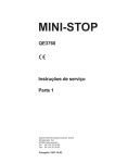
Hydraulic terminal crimping tool Operating Instructions
Hydraulic crimping tools
„HC25-12“
Art. 216124
„HC42-12“
Art. 216125
Q
DIN EN ISO 9001
ZERTIFIKAT
...convincing solutions
1. Technical data
Area of application:
Scope of delivery:
Oil type:
Safety:
Structure:
Guarantee:
For the creation of an electrical connection by means of compression
Hydraulic hand pliers in a black plastic case, without dies.
ISO class viscosity 15
The tool is fitted with a safety value that has been set at the factory.
The working head can be rotated by 180° to make it easier to adapt to
the operation to be carried out. The crimping tool does not protect the
operator when working on cables that carry power.
2 year guarantee if used for the purpose it is intended.
2. Area of work
• Pressing force in kN: 120 kN
• Working pressure in bar: 700
• Opening/ Hub: 216124: 25 mm / 216125: 42 mm
• Pressing width: wide
• Art. 2166124:
Crimping range cable lugs: standard Cu 10-400 / DIN Cu 10-300 / DIN Al 16-240
Crimping range connectors: Cu 10-185 / DIN Cu 10-150 / DIN Al 16-120
• Art. 216125:
Crimping range cable lugs: standard Cu 10-400 / DIN Cu 10-300 / DIN Al 16-240
Crimping range connectors: Cu 10-400 / DIN Cu 10-300 / DIN Al 16-240
• Dual-piston pump
• Weight in kg: 216124: 6,2 / 216125: 8,2
• Weight set in kg: 216124: 7,7 / 216125: 9,7
3. Operating instructions
CAUTION! TOOLS MAY NEVER BE USED WITHOUT FIRST INSERTING THE PRESSING DIES.
Ensure that the pressing dies fit precisely to the appropriate area and are seated perfectly in
the holders.
OTHERWISE THIS MAY CAUSE SERIOUS DAMAGES OR BREAKAGES AND THE GUARANTEE WILL
BE VOIDED.
Introduction:
Before starting up the tool, read the operating instructions first.
All current-carrying elements in the area you are working in should be disconnected.
Otherwise the protective procedures for working in the vicinity of components under current
must be implemented. (DIN EN 50110).
english
Do not use the tool if you are tired or under the influence of medication, drugs or alcohol.
Take into account the valid accident prevention and safety regulations and use the tool exclusively for the purpose for which it is intended.
The operating instructions must always be carried with the tool.
The instructions must have been read and understood by the user.
The operator must ensure that this is the case.
Performance characteristics:
• 12 tonnes of pressing force for maximum performance
• 180° rotating crimping head. Can thus be mounted even in places that are difficult to
access.
• The manual return enables the operator to bring the piston back to the starting point in the
event of a faulty pressing.
3.1.
Preparation:
• Select the appropriate pressing dies for the connection to be pressed.
• Insert the pressing dies in the tool head. All of the pressing dies that can be used in these
models are half-circles, regardless of the type of crimping or pressing being carried out. They
are made up of two parts with identical external measurements, so that they both can be
inserted at will into the piston or the head.
• The procedure for inserting pressing dies is identical for mounting to both piston and head.
• The dies are inserted via the guides until they come to a stop at the blocking pin.
• Then the pin is retracted using the release button and the die inserted further until it is held
by the pin and clicks into place.
Die holder
...convincing solutions
HAUPA® GmbH & Co. KG, Königstraße 165-169, D - 42853 Remscheid,
Phone: +49 (2191) 8418 - 0. Fax: +49 (2191) 8418 840, E-Mail: [email protected]. Errors and technical changes reserved.
• When inserting into the piston, you must only ensure that this is pushed far enough forward
for the release button to be visible and accessible.
• To remove the dies, in both instances, the relevant release button must be activated.
Then allow the dies to slide out. Please note that in order to remove the inserts at the piston,
the steps listed above must be carried out in reverse order.
3.2.
Start
• Bring the tool to the working position.
• Select the appropriate pressing dies for the connection to be pressed.
• Insert the pressing dies in the tool head.
• Feed the conductor into the connector.
• Place the connector between the two pressing dies.
3.3.
Approach of the pressing dies (closing feed rate)
• Hold the tool securely and press the mobile lever arm to move the piston quickly forwards
until the pressing dies meet the connector to be compressed.
3.4.
Compression (working feed)
• As soon as the pressing dies start to compress the connectors, the system automatically
switches from closing feed to working feed.
• Press until the pressure limiter can be heard or the pressing dies meet and a perceptible
discharge of the pump occurs.
IMPORTANT only applies to Art. 216124
If connection sleeves with braided wires with cross-section in excess of 185 mm2 are to be
compressed, the cable must be stripped approximately 50 mm further than the amount that
will be inserted into the sleeve in order to enable removal from the device head after pressing.
If this is not done, the device must later be pushed to the end of the cable or the cable be
stripped after crimping.
3.5.
Releasing the pressing dies (return of the piston)
• Activate the release value lever on the tool so that the piston automatically returns to the
basic position or to the desired position.
• This can be carried out during the crimping if you have made an error in the selection of the
connector or the die.
english
4. Diagnosing faults
The following section describes three possible reasons for faulty operation as well as the ways
in which they can be eliminated.
4.1.
With every actuation of the lever the piston experiences a feed motion and then returns back to
the starting position.
CAUSE:
Air in the hydraulic circuit.
SOLUTION:
Let the air out of the hydraulic system; See the explanations in the "Checking
the oil level" section.
4.2.
The feed from the piston is fine, but it is not possible to fully complete the pressing.
a) CAUSE:
Lack of oil.
SOLUTION: Fill the tank; See the explanations in the "Checking the oil level" section.
b) CAUSE:
As a result of contamination in the closing stamp, oil exits the pressure
limiting valve.
SOLUTION: Hold down the release level and operate the drive lever forcefully
approximately 10 times in series. This should wash away the contaminations in
the safety value so that the pump works properly again.
If the tool still does not work, send the tool to the HAUPA service centre for fine tuning by our
specialist staff. Do not send accessories as these are not necessary.
4.3.
Tool oil loss.
CAUSE:
SOLUTION:
Sealing rings are defective or deformed
Please send the tool to the HAUPA service centre. Do not open!
...convincing solutions
HAUPA® GmbH & Co. KG, Königstraße 165-169, D - 42853 Remscheid,
Phone: +49 (2191) 8418 - 0. Fax: +49 (2191) 8418 840, E-Mail: [email protected]. Errors and technical changes reserved.
5. Care and maintenance
5.1.
Cleaning
Careful cleaning of the tool, in particular, the moving parts contributes towards a longer useful life.
Remember that dust, sand, environmental influences, in particular a high salt index, and dirt in
general are extremely damaging to hydraulic tools.
Particular care should be taken when cleaning the pump drive piston and the piston. The tiniest of
contaminations may scratch the walls of the cylinder and damage the leak-proof seals.
For the correct cleaning of the piston, we recommend extending the piston and then cleaning it with
a high-quality, non-corrosive solution.
5.2.
Storage
To prevent damage to the tool as a result of bumps, dust etc. you should if possible store the tools
in the carry bag in a warehouse.
5.3.
Checking the oil level
The oil level in the tank should be checked at regular intervals, in particular, when it has been used
for a long time and topped up whenever necessary.
Oil can
• Refilling or filling with oil
• Use only the oil name in section 1 or purchase from the HAUPA service centre (Art. 216254).
• Never use old oil.
• The oil must be clean and may not contain contamination.
• Hold the tool upright so that levers 1 and 4 are pointing upwards.
• Move the piston back as far as it will go, turn the moveable lever (1) by a quarter turn and hold,
press the release button until the piston stops on the return journey.
• Remove the stop screw (3) using an Allen key.
• Unscrew the fixed arm (4) and remove.
• Hold the upper section of the tank (5) with one hand and with the other hand
• remove the lid (4). Fill the container to the top and replace the lid. The oil must be distributed
throughout the entire container, so that it is impossible for air to enter into the circuit.
• Move the piston forwards with the moveable lever and check for perfect functionality.
english
Bleeding the hydraulic circuit
• After the lid (6) of the tank has been removed, operate the moveable lever (1) several times
to extend the piston.
• Move the piston back again fully, and use a screwdriver or similar object to press the
release button to enable the oil to flow back into the container.
• Repeat these steps at least 5 times to fully bleed the entire hydraulic circuit and to remove
all air pockets.
• Carry out step 5 from the previous section – „Refilling or filling with oil“.
• Apply the handle, tighten the locking screw and check the functionality.
If the tool still not does function correctly despite this maintenance please contact the
HAUPA service centre. Only use the oil named in section 1.
• When changing the oil, dispose of the old oil under strict observation of the applicable
legal requirements.
5.4.
WARNING NOTES!
Caution:
Do not attempt to force the head to turn when the hydraulic circuit is pressurised.
Guarantee:
2 year guarantee when used for the purpose it is intended when the annual maintenance intervals are maintained by an authorised HAUPA service centre. We reserve the right to rework the
product.
Disposal:
Individual components must be disposed off separately.
The oil must be drained and disposed of at the designated points.
Caution:
Hydraulic oils represent a risk to the groundwater. Uncontrolled drainage or incorrect disposal
carries penalties. (Environmental Liability Law)
The remaining components of the aggregate must be disposed in accordance with the relevant
environmental standards.
The disposal should be carried out by authorised specialist companies. The free return to the
manufacturer cannot be guaranteed.
WITH EVERY REPLACEMENT PART ORDER, INCLUDE THE FOLLOWING INFORMATION:
1) Article number
2) Article description
3) Reference to the operating instructions and/or date
4) Tool type
5) Serial number of the tool
The guarantee is voided if you use parts that are not original replacement parts from HAUPA.
...convincing solutions
HAUPA® GmbH & Co. KG, Königstraße 165-169, D - 42853 Remscheid,
Phone: +49 (2191) 8418 - 0. Fax: +49 (2191) 8418 840, E-Mail: [email protected]. Errors and technical changes reserved.