1
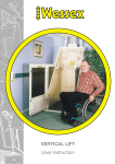
‘HOMELIFT’
VM TÜV RANGE
USER MANUAL
CONTENTS
Page
1. INTRODUCTION
4
2. SAFETY NOTE
5
2.1 Safe Working Load …………………………………………………………………………...5
2.2. Sketch of typical Installation Arrangement ..…………………………………… 6
3. LIMITED WARRANTY
7
4. LIFT FEATURES
8
4.1 Audible Alarm …………………………………………………………………………………. 8
4.2 Vision Panels ………………………………………………………………………………….. 8
4.3 Safety Devices ………………………………………………………………………………… 8
4.3.1 Aperture Board ………………………………………………………………. 8
4.3.2 Car Sensitive Safety Edges ……………………………………………… 8
4.3.3 Under Lift Platform Sensitive Surface …………………………….. 8
4.3.4 Hold to Run Controls………………………………………………………. 8
4.4 Finishes ………………………………………………………………………………………….. 8
4.5 Door ………………………………………………………………………………………………. 9
4.6 Electrical Features …………………………………………………………………………. 9
4.7 Emergency Features ……………………………………………………………………… 9
4.7.1 Battery Back-up Features ………………………………………………. 9
4.7.2 Emergency Lowering by Lift User …………………………………… 9
4.7.3 Emergency Lowering at Pump Unit ……………………………….. 9
4.7.4 Hydraulic Pipe Failure ……..…………………………………………….. 9
4.8 Fire Sealing ……………………………………………………………………………………. 9
4.9 Design Features…..………………………………………………………..……………….. 10
4.9.1 Door Closing Strap …………………………………………………………. 10
4.9.2 Grab Handles …………………………………………………………………. 10
4.9.3 In-car Lighting ………………………………………………………………… 10
4.9.4 In-car Seating …………………………………………………………………. 10
4.9.5 Lap Strap ………………………………………………………………………… 10
4.9.6 Radio Control …………………………………………………………………. 10
4.9.7 Telephone ..……………………………………………………………………. 10
4.9.8 Autohoming ……………………………………………………………………. 10
4.9.9 Auto-door Closing …………………………………………………………… 10
4.9.10 In-car Key-switch ………………………………………………………….. 10
4.9.11 Smoke Alarms ……………….……………………………………………… 10
4.10 Illuminated In-car Controls .…..…………………………………………………….. 11
4.11 Wall Mounted Call Stations .….……………………………………………………… 11
Homelift (VM TÜV) – User Manual VM00 7104
2
5. OPERATING INSTRUCTIONS
5.1 Homelift Control Buttons………………………………………………………………...
5.2 Calling and entering the Lift ……………………………………………………………
5.3 Travelling to the desired floor…………………………………………………………
5.4 Changing direction of travel…………………………………………………………….
5.5 Vacating the Lift……………………………………………………………………………….
5.6 After Use………………………………………………………………………………………….
5.7 Use of Alarm…………………………………………………………………………………….
5.8 Courtesy Lights…………………………………………………………………………………
12
12
13
14
14
14
15
15
15
6. TROUBLE SHOOTING
6.1 Electrical Power Failure……………………………………………………………………
6.2 Door Opening Failure………………………………………………………………………
6.3 Emergency Lowering (Using in-car controls)……………………………………
6.4 Emergency Lowering (At pump unit)……………………………………………….
16
16
17
18
18
7. SERVICING & INSPECTION
19
8. ROUTINE CARE AND MAINTENANCE
20
9. EMERGENCY BREAKDOWN SERVICE
21
10. CHANGE OF USE
22
11. APPENDICIES & QUICK START GUIDE
APPENDIX A – Calling the lift (step by step guide)…………………………………
APPENDIX B – Calling the lift (step by step guide)………………………………..
APPENDIX C – Changing Direction of Travel (step by step guide)………….
APPENDIX D – EC Declaration of Conformity…………………………………………
APPENDIX E – Manufacturer Details…………..…………………………………………
23
24
25
26
27
28
Homelift (VM TÜV) – User Manual VM00 7104
3
1.
INTRODUCTION
Thank you for deciding to purchase the Homelift. The range of Homelifts combines the latest
technology and design making them easy to use and less obtrusive in your home, whilst offering long
service and reliability.
The Homelift is a direct acting hydraulic lift designed for single person use in a domestic dwelling.
When travelling in the lift car, the person must be either seated or in a wheelchair. There are six lift
types available:
VM30 compact non-wheelchair model 3m maximum travel height.
VM31 wheelchair model 3m maximum travel height.
VM36 large wheelchair model 3m maximum travel height.
VM50 compact non-wheelchair model 3.5m maximum travel height.
VM51 wheelchair model 3.5m maximum travel height.
VM56 large wheelchair model 3.5m maximum travel height.
The manufacturer has extensive experience in providing products that aid mobility and is the
pioneer of the majority of today’s domestic lifts. With this background and many years experience in
the manufacture and installation of Vertical Lifts, the manufacturer is clearly the most experienced
company in the market place today. Our in-depth knowledge of associated building and electrical
work and management expertise ensures that installations are completed with the minimum of
inconvenience.
This instruction manual will help you become accustomed with your lift.
We ask that you study this manual and become familiar with the step by step instructions.
Ensure that a nominated person is also familiar with the instructions, especially the operating
procedures in the unlikely event of a breakdown.
Keep the manual in a safe place for future reference together with the electrical wiring diagram.
The door release key should always be kept clipped in its place inside the lift car on the opposite
side to the control console.
The pump box key and call station keys (Optional) should be kept in a safe place.
Homelift (VM TÜV) – User Manual VM00 7104
4
2.
SAFETY NOTES
Children must not be allowed to tamper or play with the lift or tracks. Joyriding is dangerous. It is
strongly recommended the key-switch option is fitted when young children are in the dwelling or
likely to visit. The lift controls can then be turned off by the wall mounted control stations, and the
key removed to prevent unauthorised use.
Children must be supervised at all times when the lift is in use.
During travel do not impede the car or aperture board. Ensure that all persons, especially children
and pets, are kept clear of the lift prior and during travel. Obstacles must not be placed on the
aperture board or beneath the car.
IMPORTANT! Keep all parts of your body inside the lift at all times, and do not lean out of lift.
Please remain seated whilst travelling in the lift.
2.1. SAFE WORKING LOAD
The MAXIMUM safe working load of the lift is 250kg. Never exceed this capacity.
The lift must never be used for anything other than the intended use. It must never be used for
transporting furniture or any other type of goods.
The safe working load of the aperture trap board is 250kg. Never place furniture, ladders or any
permanent loads on top of the trap board. It must be kept clear at all times.
The seat has a safe working load of 150kg. (Option)
Homelift (VM TÜV) – User Manual VM00 7104
5
2.2. HOMELIFT – Sketch of Typical Installation.
Ceiling
Track Guides
Wall mounted call
Station
Power Supply Unit
Orange Light on the right hand side
indicates mains power to the lift
Lift Isolator Switch
May be fitted at the
lower level
Safety Sensitive
Aperture Trap Board
Keep clear at all times
Mid Floor
Wall mounted call
Station
Safety Sensitive
Edges
Ground Floor
Power pack
(Can be fitted externally)
Vision Panels
Note: Arrangement is subject to change without notice.
Homelift (VM TÜV) – User Manual VM00 7104
6
3.
LIMITED WARRANTY
This product is warranted to be free from defects in materials or workmanship for one year (unless an
extended warranty has been purchased) from the initial date of installation. Within this period, the
manufacturer will at its discretion, repair or replace any components that fail in normal use. This warranty
does not cover failure due to abuse, misuse, accidental or unauthorised alterations or repairs.
Homelift (VM TÜV) – User Manual VM00 7104
7
4. LIFT FEATURES
The lift can be configured to include a variety of options to suit your requirements, the following
section details the features that are available for this product, and gives a brief overview into their
function and operation. Please note some of the options may not be installed on your lift.
4.1. Audible Alarm – Fitted as standard on all Homelifts, this feature provides a means of raising
attention in the unlikely event of a breakdown and or when the user could be trapped inside the lift
car. The alarm is mounted in the car on the control console. (See section 5 for more
details)
Alarm Button
4.2. Vision Panels – The lift car has vision panels as standard in the sides and door. This gives an airy
feel to the lift and reduces the amount of light loss when using the lift. All vision panels are
manufactured from toughened safety glass.
4.3. Safety Devices – There are several safety features that are included as standard on your
Homelift. These are as follows: 4.3.1. Aperture Board Sensitive Surface – If during raising or lowering of the lift, the
aperture board is impeded in any way, the lift will STOP immediately. This is achieved by the
built in safety systems which are integral to the design of the lift.
4.3.2. Car Sensitive Safety Edges – The upper edges of the lift car (sides and top of door) are
protected by sensitive devices that STOP the lift immediately if any obstruction is detected
whilst the lift is travelling upwards.
4.3.3. Under Lift Platform Sensitive Surface – The underside of the lift has a pressure
sensitive surface, which is designed to STOP the lift if an obstruction is detected. This
feature has been incorporated to protect small children in the event that they walk into the
lift area during descent. This platform will also stop the lift when it’s travelling upwards, if
the platform is pulled down.
4.3.4. Hold to Run Controls – The lift controls require constant pressure for the lift to travel.
As soon as pressure is released from the pushbutton the lift will stop.
All of the above safety devices are integral to the lift and make the Homelift intrinsically safe in any
given application.
4.4. Finishes – The interior and exterior metalwork of your Homelift is coated in a hard wearing
powder coat which will provide protection against knocks and daily usage.
The colour of your lift is pearl grey and this is complemented by lavender coloured ABS panels which
are fitted to the rear and sides within the car.
The floor is coated with an anti-slip finish which will aid traction of wheel chairs and provide a
hardwearing surface. It can be easily cleaned with a stiff brush if required.
Homelift (VM TÜV) – User Manual VM00 7104
8
4.5. Door – The door can be either powered (Optional) or manual (Standard) depending upon the
options you have selected. The lift will only function if the door is properly closed and interlocked. It
cannot be opened between floors, (except in an emergency). A powered door will open or close
automatically when the blue door button is pressed, and stop in the open or closed position. A
manual door has to be physically pushed open or closed after pressing the blue door button, or
pressing the door safety edge down.
4.6. Electrical Features – The lift operates on a dedicated 240 Volt supply that is protected by an
RCD. The supply voltage is transformed to provide all control buttons with a low voltage 24V DC
supply.
4.7. Emergency Features – The Homelift contains several facilities for dealing with emergency
situations which may be caused by external influences such as power failure etc. These are as
follows: 4.7.1. Battery Back-up Features – In the event of an electricity supply failure/power cut, the
following lift functions will continue to be in operation: Emergency Lowering Button
All Safety Devices
Powered Door (If fitted)
Stop Buttons
The Alarm
Manual Door Lock
Integral Lighting
4.7.2. Emergency Lowering by Lift User – Should the lift stop, due to a power
failure, an emergency in-car lowering button will illuminate. This will allow the
user to lower the lift to the ground level by simply pressing this button.
4.7.3. Emergency Lowering at Pump Unit – In extreme cases it may not be
Emergency Lower
possible to lower the lift using the emergency lowering button as mentioned
above. Therefore, means to do this is provided in the power pack unit itself. (See
troubleshooting section 6.4)
4.7.4. Hydraulic Pipe failure – In the unlikely event of an oil pressure pipe failure, a safety
valve will immediately stop the lift.
4.8. Fire Sealing – All models incorporate a fire seal which is effective when the car is parked at the
first floor level. It is recommended that the lift is parked in this designated ‘home’ position when not
in use.
All fire sealing arrangements are incorporated integrally to the lift and are in accordance with BS
5900.
Homelift (VM TÜV) – User Manual VM00 7104
9
4.9. Design Features – There are several design features available to help the user operate the lift,
these include the following. Please note that not all are applicable and are dependent on the model
and options selected at the point of sale.
4.9.1. Door Closing Strap – A textured rope type pull cord is fitted to all manual doors as
standard to allow the door to be closed easily from within the lift.
4.9.2. Grab Handles – With front or side mounted positions available, these handles allow
the user points on which to ease themselves into the lift car.
4.9.3. In-car Lighting – Internal illumination of the lift car is provided which automatically
switches off when the lift is not in use. The lighting is operational via battery back up in the
event of a power failure. This is fitted as standard.
4.9.4. In-car Seating – An in-car seat option is available. Maximum rated load of the seat is
150kg. The seat can fold up neatly away by simply lifting the front edge of the seat up until it
is in the vertical position.
4.9.5. Lap Strap – Where in-car seating is selected a lap strap with quick release buckle can
be offered to suit.
4.9.6. Radio Control – A radio controlled option is available to control some functions of the
lift.
4.9.7. Telephone – An in-car telephone option is available.
4.9.8. Autohoming – An autohoming option is available. This will automatically send the lift
to the upper level after a set period of time when the door is in the closed position.
(‘Homed’ position).
4.9.9. Auto-door Closing – An auto-door closing option is available. This will automatically
close the lift door after a set period of time.
4.9.10. In-car Key-switch – An in-car key-switch option is available. This will disable the up,
down and stop button on the in-car control panel. This option must only be used if the user
of the lift is not physically or mentally able to use the in-car controls. The lift must be
supervised at all times when in use.
4.9.11. Smoke Alarms – Mains powered (battery backed) smoke alarms are available. The
smoke alarms are connected to the lift and will call the lift to the upper level if triggered in
the event of a fire. Please note the lift door must be closed for this to work.
Homelift (VM TÜV) – User Manual VM00 7104
10
4.10. Illuminated In-car Controls – For ease of identification all control buttons within the car are
illuminated. Each button controls the function/operation of the lift.
To aid the user in operation, the buttons that are illuminated are
the only buttons that can be operated at that time. The lift unit has
in built logic based on its location.
If for example, you are at the upper level, the green up arrow will
not be illuminated because the only travel options available to you
are to either open the door or to go to the lower level.
The reverse applies if you are at the ground level. These features
are designed to get you up and running with the minimal amount of
training possible.
A more detailed explanation of operation is given in section 5.
Fig 4.10 - In Car Control Console
4.11. Wall Mounted Call Stations – Call stations are positioned at the upper and ground levels.
These call stations are used to call the lift or send it to a parked position when the lift is not in use
and to operate the powered door. (Powered door is optional)
A two way personal key-switching facility can be provided if required. This prevents the up and down
pushbuttons from operating the lift. (Shown in Figure 4.11 below)
Please note there is no specific on or off position for the key.
Fig 4.11 - Wall Mounted Call Station (Key-Switch and Power Door Option)
Homelift (VM TÜV) – User Manual VM00 7104
11
5.
OPERATING INSTRUCTIONS
5.1. Homelift Control Buttons – The diagrams below are typical arrangements for the layout of the
in car controls and wall mounted call station for your Homelift. It is recommended that you study
the diagrams to make yourself familiar with each of the controls. The design of your Homelift is
intended to be straightforward in terms of its operation.
Alarm Button
In Car Light Button
Emergency Lowering
Door Button
Down Direction Button
1
1
Stop Button
Up Direction Button
Note 1: up and down buttons may be reversed; depending on which side the In-Car
Control Console is mounted.
Fig 5.1 - Layout In-Car Control Buttons
Up Direction Button
Stop Button
Down Direction Button
Powered Door Open/Close Button
(Optional)
Key-Switch (Optional)
Fig 5.2 – Wall Mounted Call Station Buttons
Homelift (VM TÜV) – User Manual VM00 7104
12
5.2. Calling and entering the Lift – the following sequence assumes the lift is parked at the upper
level, and the key-switch (if fitted) has been turned off, and you are at the lower level.
Insert key and turn the key-switch (If fitted) on the wall mounted
call station (See Fig 5.2).
Press and hold the Down (Green Arrow) direction button.
The lift will descend to the lower floor level and automatically
stop.
Opening the Door
For manually operated doors. Depress the door safety edge (on top of the door)
and gently pull the door open. At this point all the lights in the car will
illuminate.
For powered doors press and release the Blue door button on the wall mounted
call station. At this point all the lights in the car will illuminate.
Notes: A powered door can be opened manually by following the manually operated
door instructions. It will require a small amount of force to disengage the driving
mechanism. This must be manually re-engaged before the power door will operate
again.
WARNING! Do not lean on the safety edge without opening the door otherwise
the lift will not operate. You will need to reset the door by opening and closing the
door if you do this.
Entering the Lift (with Seat)
Enter the car and use the seat provided. Use the lap strap if fitted. (Option)
Entering the Lift (Wheelchair Model)
It is recommended that you reverse the wheelchair into the car wherever
possible.
Closing the Door – Manually
The door can be closed by pulling the door closing strap until the door latches
shut. The door must be fully closed and latched before operating the lift
otherwise the lift will not function; this is part of the inbuilt safety mechanism.
Closing the Door – Powered Option
Press and release the Blue door button and the door will close and lock
automatically.
Homelift (VM TÜV) – User Manual VM00 7104
13
5.3. Travelling to the desired floor level.
The door must be closed and locked before the lift will travel. The stop button will
illuminate to confirm the door is closed and locked. There may be a small time delay
after closing the door for this to occur.
Press and hold the direction (Green arrow) button to travel, the
lift will start to move.
Note: The stop button can be used at any point during travel if required.
5.4. Changing Direction of Travel
If you wish to return to the floor that you have just departed from, mid journey, you can simply stop
the lift by: Releasing the direction (Green arrow) button. The lift will stop.
After a 3 second delay, the Up and Down (Green Arrow) buttons will illuminate.
Press and hold the appropriate direction button, the lift will travel to the
selected level and automatically stop.
5.5. Vacating the lift
Once the lift has arrived at the desired level the door can be opened.
Opening the Door – Manually
The door can be opened manually by either, press and releasing the Blue door
button and gently pushing the door open.
Or by pressing the door safety edge down and gently pushing the door open.
Opening the Door – Powered Option
Press and release the Blue door button and the door will open automatically.
Move forward and exit the lift. Close the door either manually, or by pressing and releasing the Blue
door button on the wall mounted call station.
Homelift (VM TÜV) – User Manual VM00 7104
14
5.6. After Use
When the lift is not in use, it is recommended the lift is parked at the first floor level. This ensures
the fire seal is maintained between the lower and upper level. To do this press and
hold the up direction (Green Arrow) from the wall mounted call station. The lift will
travel upwards and stop automatically at the upper level.
When the lift has stopped at the upper level, turn the key-switch (if fitted) to prevent unauthorised
use.
5.7. Use of the alarm
In the event of an emergency and if assistance is required, press and hold the alarm
button.
Please note this will only alert someone within hearing distance of the lift.
5.8. Courtesy Lights
The lift car is fitted with courtesy lights which will illuminate in the following
situations: When the door safety edge is pressed.
By pressing and releasing the In Car Light push button (see Fig 5.1).
When the Blue door button is used.
After calling the lift and within a set period, the lights will automatically go out. They will illuminate
again when the door is operated.
Homelift (VM TÜV) – User Manual VM00 7104
15
6.
TROUBLESHOOTING
Check the following if the lift will not operate:Open and close the door. Ensure it is fully closed and locked.
There are no obstructions under the lift.
There are no obstructions on top of the aperture trap board.
Turn the key-switch if fitted. (Please note there is no specific on or off position)
The orange light on the power supply unit is illuminated. (Refer to Section 6.1.)
6.1. Electrical Power Failure
The orange light on the right hand side of the power supply unit is illuminated when there is mains
power to the lift. (Reference page 7) If the orange light is not illuminated check the following:The lift isolator switch is on and the fuse is ok. (This should be located near the lift)
The main distribution lift circuit breaker and RCD are both switched on.
In the event of a power failure the lift has a battery back-up feature that enables the following
features to operate: Lift lights
Lift alarm
Door operation
Descent using the in-car emergency lowering button
Lift safety edges.
Please note the self levelling device will not function (refer to note below) in the event of mains power
failure. A ‘Shoot Bolt’ safety device restricts the distance the lift can creep down when the lift is at
the first floor position. If the lift is left for a long period of time with no mains power, it will stop on
the shoot bolt and can NOT be lowered by either the battery backed emergency lowering, or the
manual emergency lowering. The lift can only be re-used when the mains power returns.
The lift is fitted with a self-levelling device. When the lift is left at the upper level it will gradually
creep down a maximum of 25mm, the lift will then automatically re-level to the upper level. If the
lift creeps up when at the upper level, it will automatically re-level down to the upper level.
Homelift (VM TÜV) – User Manual VM00 7104
16
6.2. Door Opening Failure
Both manual and powered doors can be opened from the inside or outside of the lift car by using the
door release key supplied with the lift. See Figure 6.2.
For safety reasons it is recommended that the door release key
should be used by someone stood externally from the lift. It should
NEVER be used from inside the lift car if the lift car is not parked at
the landing level.
To open the door; use the following procedure: Ensure that the lift is either positioned at the ground floor
or the upper landing level.
Place the key in the bottom of the slot in the door panel and
gently push and lift up as in Fig 6.21
Gently push or pull the door open whilst holding the key.
Fig 6.2 Door Release Key - Opposite
In Car Call Station)
Safety Note:
In the interests of Health & Safety, please ensure that the Door
Release Key is never left in the lock access hole. To guard against
this, the key is fitted with an integral spring.
2
It is recommended that the key is stored opposite the control
console as shown in Fig 6.2.
1
Fig 6.21 Door Release
Homelift (VM TÜV) – User Manual VM00 7104
17
6.3. Emergency Lowering (Using In-Car Controls).
If your Homelift has been rendered inoperable due to a power failure, it can be
lowered using the emergency lowering button inside the car. This can be
achieved by following the procedure below: Ensure the ground floor is clear of any obstructions, if you are unsure you
may need someone to check for you.
When the floor area is clear, press and hold the emergency lowering
button. (Figure 6.3) The lift will descend to the ground level and
automatically stop. You can now vacate the lift car.
Note: All safety devices are still operational.
Fig 6.3 - Emergency Lower Button
6.4. Manual Emergency Lowering at the Pump Unit
This procedure below must be carried out by an authorised person and only used if the procedure
given above in 6.3 fails to work. Note: This procedure will only work if the lift is at least 50mm
below the upper level.
Ensure both the ground floor area underneath the lift and
upper floor level around the lift is kept clear from any children,
pets or other obstructions.
The lift must be under constant surveillance whilst this
procedure is carried out.
Ensure the electrical supply to the lift is switched off.
Open the lid of the Hydraulic pump using the key provided with
the lift. (See Fig 6.4)
Pull the red knob and push the black knob simultaneously as
shown (See Fig 6.41) and the lift will begin to lower, releasing
the valve will stop the lift.
When the lift has reached the ground level the door can be
opened and the user can vacate the lift.
Fig 6.4 - Pump Unit
WARNING! Safety features will not
work when manual emergency lowering
is used.
Safety Note:
Important before starting any of the
procedures mentioned above, ensure
the area beneath the lift is clear of any
obstructions
Fig 6.41 - Lowering Valves
Homelift (VM TÜV) – User Manual VM00 7104
18
7.
SERVICING & INSPECTION
When installed your lift would have been commissioned and inspected to ensure safety and
reliability. The Homelift should give you many years of service as long as regular maintenance is
correctly carried out. Failure to do this could lead to unreliable or unsafe operation.
The Homelift is guaranteed for 12 months, unless you have purchased an extended warranty at the
same time as purchasing your Homelift. Alternatively, you may wish to establish a maintenance
agreement that will provide for routine servicing for a period of time thereafter.
The manufacturer recommends the Homelift is checked and serviced every 6 months.
The lift must be serviced to the BS 5900 schedule, in addition to this there are routine check lists and
lubrication schedules which includes checks on the following: Suspension member checks.
Safety-interlock checks.
Electrical integrity checks.
Hydraulic safety valve checks.
Hydraulic leakage checks – (e.g. hoses and fittings etc.).
Lubrication.
Screws and Nuts (as applicable).
For all enquiries regarding service please contact your service company.
Homelift (VM TÜV) – User Manual VM00 7104
19
8.
ROUTINE CARE AND MAINTENANCE
To ensure that your Homelift continues to offer reliable service and continues to keep its
appearance it is recommended that routine cleaning of the unit is carried out as required. The
Homelift can be treated as any other normal household appliance.
Before carrying out any cleaning work it is important that the main supply is switched off to the lift.
This is located adjacent to the lift.
A variety of household cleaners can be used to clean your Homelift, but please be sure that
you do not use abrasive cleaners of any form and that the cloth used is damp and not
soaking wet. Please read the cleaning product label before applying to the Homelift.
It is important that the aperture ‘in fill’ or trap-board is not made wet in any way as this may
change the strength characteristics of the board and cause a potential hazard. A weakened
trap board will need to be replaced.
Transparent (glass) panels can be cleaned with a household glass cleaning product. Do not
use abrasive cleaners and again please read the product label before applying to the
Homelift.
Important safety note
Do not under any circumstance paint the lift or the guide tracks as this could seriously impede the
sliding mechanism and therefore the running of the lift. Additionally, any such action will render the
warranty void.
Homelift (VM TÜV) – User Manual VM00 7104
20
9.
EMERGENCY BREAKDOWN SERVICE
For information on breakdown cover and servicing please contact your service company.
Homelift (VM TÜV) – User Manual VM00 7104
21
10. CHANGE OF USE
During the useable life of the Homelift, it may be possible that circumstances change and hence the
function of the lift may not be suitable to the new situation. Examples of this are: A change of type and weight of wheelchair.
A change in the user’s ability.
A change in user.
An installation at another site.
A change in duty cycle (number of journeys per hour).
Any such changes to the use of the lift must be discussed with your service provider, who will be
best able to advise whether any alterations to the installation will be required.
Homelift (VM TÜV) – User Manual VM00 7104
22
APPENDICES & QUICK START GUIDE
Note:
The following appendices are designed to be a step by step guide and can be removed from this
manual if required. The pages can be laminated and placed at the upper and lower locations for
reference purposes.
Homelift (VM TÜV) – User Manual VM00 7104
23
Appendix A – ‘Calling the Lift’ & travelling up (with lift at upper
floor level, and user at ground floor level) step by step guide.
1. If the controls are not working check the
key-switch is on (if fitted). See Figure 1.
Note: The ON position will change, as both
upper and lower call stations can be turned
on & off.
2. Press & hold the Green down
direction arrow button.
Figure 1 – Wall Mounted Call Station
3. Allow the lift to descend and stop at the
lower floor level.
1
Push Down
4. Press & release the Blue door
button. Note: For a manual
door press down the safety edge
& pull the door open.
5. Enter the lift by reversing your wheelchair
into the car, or use the seat if fitted. Figure 3
2
Pull
Figure 2 – Manually Open the Door
6. Press & release the Blue door
button to close the door.
(Pull close if manual door)
7. Press & hold the Green up
direction arrow button on the
control console. Figure 4
Figure 3 – Entering/Exiting the Car
8. The lift will now travel to the upper floor
level and stop.
9. When the lift has stopped, press
and release the Blue door button.
(Push open if manual door)
10. Exit the lift and close the door, by
pressing the Blue door button.
(Push close if manual door)
Figure 4 – In-car Control Console
Appendix B – ‘Calling the Lift’ & travelling down (with lift at lower
floor level, and user at upper floor level) - step by step guide.
1. If the controls are not working check the
key-switch is on (if fitted). See Figure 1.
Note: The ON position will change, as both
upper and lower call stations can be turned
on & off.
2. Press & hold the Green Up
direction arrow Button.
Figure 1 – Wall Mounted Call Station
3. Wait for the lift to rise to the Upper floor
level and stop.
4. Press & release the Blue door
button.
(Push open if manual door)
5. Enter the lift by reversing your wheelchair
into the car, or use the seat if fitted. Figure 3
1
Push Down
2
Pull
Figure 2 – Manually Open the Door
6. Press & release the Blue door
button to close the door.
(Pull close if manual door)
7. Press & hold the Green down
direction arrow button on the
control console. Figure 4
Figure 3 – Entering/Exiting the Car
8. The lift will now travel to the lower floor
level and stop.
9. When the lift has stopped, press
and release the Blue door button.
(Push open if a manual door)
10. Exit the lift and close the door, by
pressing the Blue door button.
(Push close if manual door)
Figure 4 – In-car Control Console
Appendix C – Changing direction during travel - step by step
guide.
DURING TRAVEL IN ANY DIRECTION
1. Release the Green direction arrow button.
Figure 1 – In-car Control Console
2. Wait for 3 seconds.
3. Press and hold either Green direction
arrow button.
Note:
You can reverse your direction of travel or carry on with
the original direction of travel. This is indicated by the
fact that both Green arrow buttons are illuminated on
the control console.
EC Declaration of Conformity (Original)
The manufacturer of the products covered by this declaration is: ‘Wessex Lift Co Ltd’, Budds Lane, Romsey, Hampshire,
SO51 0HA, United Kingdom
Declare that under sole responsibility that the products
Vertical Platform Lift ‘Homelift’
Known as Model(s) VM Range
Serial No(s) ________________
are in conformity with the provisions of the following EC directives(s) when installed in accordance with the
installation instructions.
Directive(s):
Machinery Directive: 2006/42/EC
Low Voltage Directive: 2006/95/EC
Electromagnetic Compatibility Directive: 2004/108/EC
Conformity Assessment Procedure
As defined in Regulation 13 of Supply of Machinery (Safety) Regulations 2008.
Conformance of a type sample with the regulations from the EC directives has been certified by the notified
body TÜV Rhineland and through the manufacturer.
Approved by the notified body - TÜV Rheinland Industrie Service GmbH, Alboinstraße 56, 12103 Berlin.
(Notified Body 0035)
The technical documentation required to demonstrate that the product meets the requirements of the
above directives has been compiled by the signatory below and is available for inspection (at the
manufacturers premises) by the relevant enforcement authorities.
The CE mark was first applied at the manufacturers’ premises in 2009.
The products described above comply with the essential requirements of the directives specified.
Signed:
Authority:
Managing Director
Date:
29/12/2009
Manufacturer Information
Model:
Manufacturer:
Address:
Homelift (VM30, VM31, VM36, VM50, VM51 & VM56)
Wessex Lift Co Ltd
Budds Lane
Romsey
Hampshire
SO51 0HA
Telephone Number:
0044(0) 1794-830303
Fax Number:
0044(0) 1794-512621
E-Mail:
[email protected]
Website:
www.wessexlifts.co.uk
©Copyright 2009
All Rights Reserved
Except as expressly provided below, no part of this manual (which are the original instructions) may be reproduced,
copied, transmitted, disseminated, downloaded or stored in any storage medium, for any purpose without the express prior
written consent of the manufacturer. The manufacturer hereby grants permission to download a single copy of this manual
and of any revision to this manual onto a hard drive or other electronic storage medium to be reviewed and to print one
copy of this manual or of any revision hereto, provided that such electronic or printed copy of this manual or revision must
contain the complete text of this copyright notice and provided further that any unauthorised commercial distribution of
this manual or any revision hereto is strictly prohibited.
Information in this document is subject to change without notice. The manufacturer reserves the right to change or
improve its products and to make changes in the content without obligation to notify any person or organisation of such
changes or improvements.
RECORD OF REVISIONS
Revision
Revision
Date
Description
ECO
A
20/07/2011
Production Issue
1419
B
01/02/2012
Seat Details Changed - Supplier Change
1436