1
15.12.2014
User’s manual (Firmware v3.20)
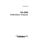
Device description
Pulsar 3 is a fast, professional battery charger with an integrated balancer. A newly designed synchronic digital
converter operates with precision and efficiency unmatched by other devices of similar type due to the DSP
(Digital Signal Processor) control. Power, work precision and ease of use were the key focus during the device’s
construction. The newest technology, rarely used in model chargers, guarantees an optimal operation of battery
packages. Impulse work in the reflex mode prevents the memory effect and the lazy battery effect in NiXX
batteries as well as lessens the threat of unbalancing in LiXX batteries. The real impulse mode “Fastmod” for Lixx
and Pb batteries can shorten the charge time even by 30-40%. The integrated high-powered balancer equalizes
the packages in a very short time, without unnecessary prolonging the process, thus keeping the singular cells’
voltage perfectly equalized. The multiple algorithms operating simultaneously, which detect the level of the cells’
voltage, as well as the capacity limiter and an integrated temperature indicator, protect the packages from
overloading and damaging. The processes’ parameters can be seen on the backlit graphic displayer. The selfexplanatory single Rotary knob, as well as twenty integrated memory banks enable frequently used processes to
be chosen faster, make for easier operation. An SD memory card enables recording the data from all of the
processes, which can then be analyzed via the Pulsar Graph program on a PC or notebook, and helps detect
damage earlier. By analyzing diagrams containing the gathered data, it enables tracing the charging packages’
ageing. Updated data from the process undertaken are sent to a PC through USB or radio data transmission
system (BT), which may in the future send data to cell phones. The charger protects batteries from deep
discharge as well as overloading by controlling the charging batteries’ (12, 24 and 48V) parameters, thus
protecting them from damage. A separate AC adapter with a power limiter enables to adapt the work parameters
to a particular charger. Pulsar 3 is protected from reverse connection both at input and output. Pulsar 3, as one
of the few modeling chargers, is equipped with a system that prevents electric arcing when high voltage packs are
plugged in. The device’s firmware update also is possible via the Internet.
1
pulsar 3
Table of content
Chapter
Page
_____________________________________________________________
1.
Device description
1
2.
Technical specification
3
3.
Precautions
3
4.
Scope of use
3
5.
EU – certificate of conformity
4
6.
Features
4
7.
Definitions, abbreviations and symbols
4
•
Battery types
4
•
Modes
4
•
Parameters and abbreviations
4
8.
9.
Starting and operating
5
•
Connecting the balancer
6
•
Cautions
6
Batteries (attributes)
7
10. Operating principle – general description
7
•
Main menu
7
•
Program window
7
11. „SD, BT, RTC“ settings
8
•
Memory window
8
•
Personalization through an SD memory card
8
12. Additional information concerning SD memory cards
9
13. Basic setup settings
9
14. Process set-up – charging NiCd and NiMH cells
10
15. Process set-up – charging LiXX and NiZn cells
10
16. Process set-up – charging Pb cells
11
17. Process set-up – discharge (all cell types)
12
18. Double processes set-up e.g. charging/discharging
13
19. Process set-up – Store / Condit (only LiXX)
13
20. Process set-up – Format (only NiCd and NiMH cells)
14
21. Balancer – operating
14
22. Process set-up – balancing only (Monitor)
15
23. Prozess set-up – Test
15
24. Program windows of finished processes
15
25. Process initialization
17
26. Process end, reports and alarms
17
•
Alarms – interrupting the process
17
27. Updating the software
18
28. PC software (PulsarGraph)
19
29. Appendix 1 – Balancer adapter
22
30. Index
24
2
pulsar 3
Technical specification
Battery types supported
Input/output device voltage
Automatic shutdown in case of
reaching min voltage set In the
following ranges:
Charging voltage*
Charging current
Max charging power
Current set-up resolution (automatic
ranges)
Discharging current
Power limiter
Temperature measurement
Voltage measurement
Current measurement
Time limit
Max balancing power
Max equalized current per cell
Min equalized current per cell
Number of cells (balancer)
Balancing precision
Backlit graphic display
Temperature ranges
Mechanical dimensions: width x
depth x height
Weight
NiCd, NiMH, NiZn, Pb, Li-Ion, LiFe, LiPo, LiHV, LiS (prepared)
12V (9**-15,5V); 24V (18-31V); 48V (36-60V)
Car battery min. 30Ah – recommended from 70Ah or stabilized 48V
power supply from 1500W
Min. 9–12 V; Min. 18–24 V; Min. 27–36 V; Min. 36–48 V
0,5-64V
1-34 NiCd and NiMH; 1 -30 NiZn; 1-24 Pb; 1-14 Li-Ion; 1-14 LiPo; 1 - 12
LiHV; 1-16 LiFe; 1-20 LiS*
0,1-25A (max. 1500W)
400 W/12V; 800 W/24V; 1500 W/48V
0,1-10,0A set in 0,1A intervals
10-25A set in 0,5A intervals
0,1-25A (400/800/1200/1500W) with energy return
0,1-25 A (100W) with heat dissipation (operating on power supply)
50-1800W (input power, on power supply)
0-99°C (0,1°C resolution)
0,1-65V
0,1-25A
24h per process (2x24h for complex processes)
60W
0,25A; 0,5A; 1,0A ( continuous current)
25mA; 50mA;100mA (continuous current)
1-16 (depending from cell type)
up to 3mV (0,003V)
240 x 64 pixels
Use: from -5 to +35°C / keeping: from -10 to +50°C
155 x 160 x 75mm
ca. 1200g
*) Using a power supply above 48 V, on individual cells (charging voltages below 5 V) a reduction of power
(protective function of the convertor) is possible.
**) Input voltage drops below 10.5 V is permitted only if batteries as a power source (not PSU) used.
Precautions
Read manual before use
Do not perform any changes or modifications to the device
Always pay attention to the right plug-in polarity
Protect from humidity and dust
Operate with a car battery only when the car engine is turned off
Protect from short circuits and reverse polarity during plug-in
During charging built-in batteries (e.g. in a transmitter) pay attention to the permitted current (e.g.
transmitters permit 0,8-1,5A)
Do not put any objects into the device through the charger’s vents
Vents must not be obscured in any way during use
Contact customer service immediately after noticing any irregularities in the device’s functioning
Use the charger only under constant supervision
The charger and batteries should always be placed on a non-flammable surface while used
Do not turn on in close proximity with people, who have artificial health-maintaining devices vulnerable to the
magnetic field (e.g. artificial cardiac pacemaker)
When supplying the charger from a car battery, it is possible that the battery will be damaged due to
excessive current draw
Scope of use
Pulsar 3 is a charger with an integrated balancer, designed to charge, test and discharge batteries used in all
lines of modeling. It may be used to charge lead batteries (car batteries), but the charger is optimised to be used
with lead-gel batteries. Using the charger for other purposes may endanger possessions and health, therefore it is
advised to use the device according to its intended purpose.
3
pulsar 3
EU – Certificate of conformity
Pulsar 3 is designed according to the general safety standards – especially home appliance’s standards,
such as EN 55014-1:2000 + A1:2001 + A2:2002 as well as EN 55014-2:1997 + A1:2001 (Cat.II)
ELPROG
ul. Przemysłowa 11
PL 35-105 Rzeszów
Features
1.
2.
3.
4.
5.
6.
7.
Pulsar 3 charger
User’s manual
Connecting cable with alligator clips
SD memory card (containing PC software, user’s manual – PDF file)
USB cable
Temperature sensor
Optional BT antenna (only if the BT module is installed)
Definitions, abbreviations and symbols (in alphabetic order)
Battery types:
NiXX
= NiCd (nickel-cadmium), NiMH (nickel-metal hybrid), NiZn (Nickel-Zinc)
LiXX
= LiPo (lithium-ion polymer), Li-Ion (lithium-ion), LiFe (LiPh), (lithium-phosphate), LiHV (Lithium High
Voltage), LiS (lithium-sulphur)
Pb
= lead battery (also lead-jelly)
Modes:
Charge = charging
Ch.Dis = charging and then discharging (a double process)
Condit = charging - discharging (capacity check) - charging to storage voltage
Disch. = discharging
Dis.Ch. = discharging and then charging (a double process)
Format = special formatting and NiXX package regeneration program
Store = special program used to prepare LiXX packages for longer storing
Test
= special program for measurement of the internal resistance of battery pack (tested by discharge
impulse)
Parameters and abbreviations:
↑ = voltage change tendency marker; displayed In the menu window above „V” (Volt) during charging and
discharging, in the balancer window it marks the cell with the highest voltage.
↓ = voltage change tendency marker; displayed In the menu window above „V” (Volt) during charging and
discharging, in the balancer window it marks the cell with the lowest voltage.
∆ (with NiCd and NiMH) = Delta-Peak value; recognizing the charging state of NiCd and NiMH batteries
∆ (with LiXX and NiZn) = cell’s voltage difference In LiXX and NiZn packages
-,- Ah = limiter capacity settings
! = the exclamation mark informs of the altered parameter value as compared to the default settings (e.g. an
altered final charging voltage value)
Ah/c = equalized capacity per cell (in the balancer window)
Auto = automatic discharge current reduction; the current, after reaching a discharge voltage of the
package/cells, will be greatly reduced in order to reach a deeper discharge without exceeding the set voltage limit
B: = current balancer power
B ("B" („B” is displayed alternately with „V”) = additional balancing (in case the battery is still not correctly
balanced after end of charging process)
Beep = acoustic signal
BT = optional wireless communication
C = {Capacity} charged or discharged capacity
c = {Charging rate} charging or discharging current according to the battery capacity in Ah: Is displayed by current
justage when limiter is active
Config_(0-9) = Config_(0-9) = Writing (and reading) of the current configuration on SD card (incl. memory)
Contr. =display’s contrast settings
Cs = {Capacity supply} displays the amount of energy drawn from the power supply from the moment the charger
was plugged in
E = {End} displayed alternately with „V” when at the end of the process the current has been reduced
4
pulsar 3
Fast = Fastmod – a fast charging mode for LiXX cells
Format = special program for formatting NiXX packages
I = {Inflex} displayed after recognizing the Inflex point at the end of the NiXX packages’ charging („I” is displayed
alternately with „V”)
Ib = max. channel balancing current (0 = only the voltage measure for cells with the balancing disabled)
Inflex = a means of early NiXX packages’ charging recognition
Invers = switches between negative and positive data display on the displayer
Last proc. = data from the last process
Light = display brightness
mΩ/c = Internal resistance (in mΩ) per cell
M = {Memory} memory place number
Monitor = displaying cell voltages by balancer port (without balancing "only Bal")
P = {Pulse} displayed alternately with „V” (Volt) during charging in Fast mode; it indicates switching to
discontinuous operating mode at the end of the charging
Pause = pause between processes indicated in seconds (e.g. during charging/discharging)
Power = input power; this setting enables to limit the input power (e.g. in weaker AC adapters or smaller supply
batteries)
Pulse = an impulse operating mode (should be enabled if the power supply is supplied by a power generator
which has a negative reaction with power consumption oscillation)
R = {Revers} displayed alternately with „V” (Volt) during charging discharging with an energy return; it indicates
the current reduction after exceeding the V rev voltage of the supplying battery
Reflex = impulse work with a discharging impulse. Suggested for all battery types!
Regen. = regeneration function initialized along with the formatting mode of NiXX packages
Rep.*99 = {Repeat} the number of double processes’ repetition (charging/discharging or format)
Revers = discharging with an energy return to the supplying battery (enables to increase the discharge power)
Ri = internal resistance of the package or cell
RTC = {Real-Time Clock} real-time clock (required for recording data on the memory card)
SD = {Secure Digital Memory Card} – memory card
Tc = {Temp. cell} package temperature measured with the temperature indicator which comes with the charger
Ti = {Temp. internal} internal temperature of the charger
Store = a program created to charge or discharge packages to the storing voltage level (LiXX)
T off = max. temperature at which the process is stopped
T on = the temperature below which the process will start (in other words – the charger waits for the package to
cool down)
V/c = {V/cell} voltage of a single cell or package – evaluated for one cell
Vc = {Vcharge} final charge voltage (can be modified individually)
Vd = {Vdischarge} final discharge voltage (can be modified individually)
Ve = {Vend} storage voltage – Store (can be modified individually)
Voff = min. supplying battery voltage, at which the process is stopped (prevents deep discharge)
Vs = {Vsupply} supply voltage (battery or supply source)
Vrev = {Vrevers} max. supplying battery voltage, which – when exceeded – will reduce the charging current with a
return (a protection for the supplying battery)
Starting and operating
Front view
1. Rotary knob
5
pulsar 3
Right side
1.
2.
3.
4.
5.
Rotary knob
Charge output minus
Charge output plus
Temperature indicator socket
Balancer socket
1.
6.
7.
8.
Rotary knob
USB socket
SD memory card
BT antenna (optional) Important: Dismount
antenna for transport!
Left side
Plugging the balancer
Pulsar 3 balancer socket – the device’s right side view
Plugging separate pins: 1 = – cell 1; 2 = + cell 1; 3 = + cell 2; 4 = +
cell 3; 5 = + cell 4; 6 = + cell 5; 7 = + cell 6; 8 = + cell 7; 9 = + cell 8;
10 = + cell 9; 11 = + cell 10; 12 = + cell 11; 13 = + cell 12; 14 = + cell
13; 15 = + cell 14; 16 = + cell 15; 17 = + cell 16. Additionally it is
possible to plug in a temperature indicator to pins 19 and 20 (NTC
10kΩ).
WARNING! Do not plug in packages, which do not have pins
specially prepared to be used with Pulsar 3, directly to the
device! Pin 20 has a positive voltage for the measuring
temperature indicator!
We recommend using our adapter to connect the balancer plugs in
the packages. It makes proper plugging with different types of pins
easier. The connection’s details can be fund in appendix 1 on page
22 of this manual.
Attention!
All battery packs equipped in balancing joints should be plugged into the balancer socket (5) first, and then
to the charger through cables (2,3). In this way the correct number of cells in the pack will always be
recognized.
Before plugging the adapter plug to the charger, first plug in the pack balancer plugs to the adapter (see
appendix 1 page 22). In this way the charger will be safe from potential damage resulting from mixing the
battery balancing plugs or from them being improperly connected. In this case a short circuit would damage
only pins or paths on the adapter board, which will work as a fuse. If damage occurs by such short cirquit, it
will result in a loss of guarantee services.
As a safety measure temperature control through a plugged in temperature indicator is always advised.
6
pulsar 3
After plugging the pack into the charger it is necessary to ALWAYS control and confirm the indicated number
of cells. Confirming an invalid number of cells in the package may result in damaging the package and
cause other material damage.
Always pay attention to the proper charging and discharging current choice. The charge must be selected
accordingly to the type, kind and size of the cells.
Charging cables with appropriate connections and pins as well as wire section fitted to the charge should be
used. Using high-current cables with silicon isolation with a 4 mm² diameter is recommended. Charging
cables should be short.
Pulsar 3 is equipped in a system, which prevents arcing when the cables are being plugged in for charging.
However, it is recommended that cables should be plugged in and out rapidly and firmly.
In order to avoid arcing, plugging and unplugging by a battery-lead connection to the power supply or AC
adapter should be done rapidly and firmly.
After unplugging the charger from the power supply, it shouldn’t be reconnected earlier than 5 seconds.
The process can be interrupted through holding down the rotary knob (interrupting the process through
unplugging the device is forbidden).
Batteries (parameters)
Type
Name
LiPo
LiHV
LiIon
LiFe
NiCd
NiMH
lithium-ion
polymer
lithiumhigh volt
lithiumion
lithiumiron
nickelcadmium
nickel-metal
hybrid
NiZn
nickelzinc
Rated voltage
3,70V
3,85 V
3,60V
3,30V
1,20V
1,20V
1,60 V
Charging voltage*
4,20V
3,30 V
4,10V
3,65V
–
–
1,90 V
Discharging voltage*
3,30V
4,35 V
3,00V
2,80V
0.90V
1,00V
1,10 V
Storing voltage*
3,80V
4,47 V*
3,75V
3,35V
–
–
–
Balancing voltage - start
3,95V
4,10 V
3,85V
3,48V
–
–
–
Max. charging voltage
4,35V
3,90 V
4,30V
3,75V
1,85V
1,85V
1,98 V
*- the voltage can be lowered by 200mV or increased by 100mV every 10mV max. Any change in
charging/discharging voltage will result in a change in max. charging/ min. discharging voltage of the same value.
Operating principle – general description
Main menu (shown in positive and negative)
Window description: From top: clock; software version (here v3.15); power (400W), on the right switched to AC
adapter, the adapter has a 240W Power, thus the power output is limited to 200W (the limitation is signalized by
an exclamation mark); personalization (pp-rc Modelbau Piechowski) shows the max. amount of characters; BT on
(radio communication activated); SD 44% (the memory card is 44% full); TC current temperature (0,0°C –
temperature indicator not plugged In); Vs adapter voltage (13,3V); Cs (0 Ah) taken capacity (e.g. car battery);,
Pulse – impulse mode activated; Revers – energy return during discharge; on the left – activated; on the right deactivated.
Pulsar 3 is operated using a Rotary knob. The dial can be turned left and right, pressed for a short (up to 1
second) or held for a long (more than 1 second) time. Both pressing and holding is confirmed by an appropriate
acoustic signal (if the sound has not been muted in the setup). Options are chosen from the list by turning the dial
to the one that interests us (blinking line), and then choosing it by pressing the dial. The value of the chosen
option is set in the same way.
After plugging in to the power supply, Pulsar 3 will display the main menu. The operation mode can be changed
(setup, one with the battery symbol, the other with a power supply symbol), after which we are redirected to the
last used memory window.
The memory window is a starting point to all process’ settings and parameters. Memory windows are numbered
from 1 to 20 (on the left side there is a frame with an „M” as well as numbers from 1 to 20). Settings made in there
remain memorized even after the charger has been turned off.
Through holding the dial for a long time we enter the program window. There we have the following options:
7
pulsar 3
Pb
lead
2,00V
2,45V
1,80V
–
–
2,55V
Attention! First connect the Pulsar 3 to a power source before connecting the battery pack. If the Pulsar 3
should be shut down, first disconnect the battery pack before disconnecting the power source! Never leave a
battery pack connected while the charger is offline!
Attention! If connecting LiXx battery packs without balancer, double confirm of the cell count is necessary for
security reasons!
Program window
Window description
-exit- – return to memory window
Mode & Accu – programming the charger’s mode and the type of charger and battery type for the memory
cell
Parameters – process parameter settings for the memory cell
Memorys – data collected from the last twenty processes
SD, BT, RTC – SD memory card options, BT parameter and clock settings
Setup – defining basic settings important for all processes
After about 10 seconds of inaction (from the last rotations of the dial) the windows will close automatically and the
charger returns to the memory window (you can also return to it by choosing “-exit-“). Further detailed setting
descriptions may be found in descriptions of specific processes.
Memorys window description. Horizontally:
“16“ – number of the process (1 - last); “4LiFe“ –
number and type of cells; “ -1,880Ah“ discharge
capacity (’+’ stands for charging); “21:35 2011-0930“ – time and date of process ending.
Top-right “12:06 2011-10-08” current time and date.
„SD, BT, RTC“ settings
Window description
-exit- – return to memory window
Import – rewriting the settings from the SD card to the charger (enables using personal settings for other
chargers): SD->P3
Export – memorizing charger settings on the memory card: This way you can use your own settings (also
on another charger) and save ten different settings under „config“ numbers from 0 – 9 (incl. process
memory). This way you can save up to 200 process settings
Backup – Archiving the recorded files in the DATA directory: there are now up in the data directory recorded
files (up to 512) into a backup directory "BACKUP (1 -3)" moved. Thereafter, the new records in the DATA
directory (on SD card) again numbered starting with 001. Up to three backup directories are managed on the
memory card. The fourth backup is the oldest of the backup catalog (after a confirmation) will be overwritten
with new data.
BT (on/off) – turning on/off wireless BT transmission. If the BT module is not plugged In a „no BT” sign is
displayed – the function is not active.
P3 xx…x – naming a specific BT device. Initially it is named „P3-„, after which 6 digits can be assigned. If
the name is to be shorter than 6 digits, insert dashes in the free spaces (up to 6 characters). These symbols
will not be considered a part of the name. Connecting other devices to the charger should be confirmed by
typing code 1234
8
pulsar 3
20:20 – clock settings
2011-05-14 – date settings
Before plugging the power supply to Pulsar 3, it is important to make sure if the memory card and the BT antenna
(optional) are in the charger. After pressing the dial on the “SD, BT, RTC” line in the program window (we go to
the program window by holding the dial from any memory window) we are redirected to the „SD, BT, RTC”
settings.
Setting the BT name is important as it will let us recognize our device easier among other devices in close
proximity. Setting the date and time are vital for recording data on the memory card. File identification is easier
thanks to this.
WARNING: as long as Pulsar 3 is connected through an USB cable wireless transmission is disabled.
The window will be exited by pressing -exit- or automatically after 10 seconds from the last dial movement.
Personalizing through an SD memory card
In the folder located on the card: PULSAR3/Setup there is a file named title.txt. The text written there is displayed
in the main menu under the Pulsar 3 logo right after the chargers startup. A simple text editing program (e.g.
Notepad) may be used to edit his text. The text may not surpass 26 characters from the English alphabet ( { ` }
inserts a narrow space). If the file isn’t to be found on the memory card, the sign „Pulse charger” will be
displayed.
Additional information concerning the SD memory card
Cards formatted in a PC (FAT16 to 2GB or FAT32 with a 4GB capacity) should be specifically used in Pulsar 3.
After turning on the charger with an empty SD card (without a folder structure) – necessary folders will be created
automatically: (PULSAR3 as well as BACKUP, DATA and SETUP). Such a card is ready to be used immediately.
The card should be inserted and removed only when the charger is not plugged into a power supply!
Basic setup settings
Pulsar 3 has two equivalent device memory settings – Setup. One of them is marked with a battery symbol and
the other with a power supply symbol. As both of them are identical they can be used freely. When for example
we operate the charger only with a power supply (or only with a battery) they can be both used with different
setup memory settings (depending on the need) with the same type of supply.
Through pressing the dial for on the “Setup” line we enter the settings from the program window (we enter the
program window by holding the dial from any memory window)
Setup windows (shown in positive and negative)
Window description
-exit- – return to memory window.
Beep – enable/disable acoustic signaling.
Pulse – enable/disable impulse work.
Revers – enable/disable discharging with an energy return do the supplying battery (Revers, must be turned
off when operating with a power supply, or it may result in damaging the supply) if it is not marked, operating
with an energy return is blocked for all memories (in a memory where the energy return was enabled, a ‘-‘
symbol is displayed before Revers)
V rev – max. battery voltage settings, after exceeding which the charge reduction will commence (Revers –
enabled), this protects the supplying battery from overloading during the energy return, especially when a
LiIo, LiPo or LiFe batteries are used (e.g. when supplying with 3 LiIo cells the voltage should be set to 12,4
V, which is about 3*4,1V – see the Charging voltage table on page 7, 15V for PB).
Power – setting the power input: 50-1800W, in 10W intervals. This can protect weaker power sources and
batteries from overcharging.
T on – setting the temperature from which the process is enabled: 25-55°C (‘-C’ disabling the function).
T off – setting the temperature from which the process is stopped: 38-60°C (‘-C’ disabling the function, the
temperature set in T off must be at least 5°C higher than T on).
V off – min. supply battery voltage below which the process will be stopped (his protects the battery from
deep discharge): 9-12V for 12V batteries and 18-24V and 36-48V for 24V and 48V batteries.
9
pulsar 3
Invers – switch the display from negative to positive.
Contr. – display contrast: 0-15.
Light – display backlight intensity: 0-15.
Pause – pause time between processes (e.g. charging/discharging in cycles): 15-900s in 15s intervals.
Process set-up – charging NiCd and NiMH cells
Window description: From top left: charging is
set; in memory window M 18; type of battery NiMh;
charging current 0,5A; “=,=Ah” – the limiter is
disabled; Inflex is disabled; reflex is enabled; ∆
4,0mV (standard value)
All process settings are conducted In a very similar way. First, choose the appropriate memory window that is to
be programmed (from M 1 to M 20). Secondly, enter the program window by holding the dial, where the “Mode &
Accu” option is selected. Here the battery type and the type of the process that is to be programmed is set. For
lithium NiXX batteries the following programs have been prepared: Disch. (discharge), Charge (charge), Dis.Ch.
(discharge/charge), Ch.Dis. (charge/discharge), Format (format).
The process parameters can be changed if necessary. Through holding the dial we enter the program window
where we chose the “Parameters” option, which enables us to set all the parameters important for the process
according to our requirements.
And so, for NiCd and NiMH:
-exit- – return to memory window.
Inflex – enables ending the process earlier. Inflex should be used only with charges higher than 1C and
accupacks with more than 4 cells. Enabling the Inflex mode is signalized (while the process is in progress)
by an „I” symbol under the battery animation.
Reflex – enables charging and supercharging NiCd and NiMh batteries without the threat of the „Memory
effect” occurring. In this charging mode short discharging impulses are emitted. Packages charged with
reflex often have a lower resistance.
∆ – „Delta-Peak“ setting, if the set value diverges from the suggested one, an exclamation mark is displayed
(! ∆). With NiCd the value May be set from 4 to 25mV and 1-15mV with NiMH.
Exiting the settings menu can be made by choosing -exit- or automatically after 10 seconds from the last dial
movement.
Warning! Checking Inflex and Delta-Peak starts after 2 minutes with NiCd and after 4 minutes with NiMH.
Caution is advised when full packages are to be plugged (supercharging them with higher charges), to avoid
overloading the packages.
Setting the charging current
After a press of the dial the required current can be set In the memory window, and after confirming (press of the
dial) the limiters’ value. The current’s value can be between 0,1A to 0,25A set in the following intervals: 0,1A
intervals up to 10,0A, 0,5A above 10A. The limiter’s capacity is set from “-,-Ah” (the capacity is not controlled) to
200Ah. Using the limiter is advised, especially with new packages which have not yet been formatted. The limiters
value should be set a bit higher then the cells capacity (by about 5-10%), which will prevent unnecessary package
overload when the proper evaluation of Inflex and Delta-Peak is impossible, as a result of unequally charged
cells.
After all settings meet our requirements we can plug in the battery packages to the charger. Before beginning
the process it is necessary to check if the number of cells in the package matches that indicated by the
charger. After adjusting the number of cells, if necessary, we can start the process by pressing the Rotary knob.
It is important to stress that the procedure described above shows how to set all of the parameters and in
practice, to start the process, it May be limited to a few steps. Proper memory setting and creating ready
programs to all battery packages is recommended as it will make operating the charger easier and faster.
Process set-up – charging LiXX and NiZn cells
All process settings are conducted In a very similar way. First, choose the appropriate memory window that is to
be programmed (from M 1 to M 20). Secondly, enter the program window by holding the dial, where the “Mode &
Accu” option is selected. Here the battery type and the type of the process that is to be programmed is set. For
10
pulsar 3
lithium NiXX batteries the following programs have been prepared: Disch. (discharge), Charge (charge), Dis.Ch.
(discharge/charge), Ch.Dis. (charge/discharge), Store (charging or discharging packages to a storing voltage
level).
The process parameters can be changed if necessary. Through holding the dial we enter the program window
where we chose the “Parameters” option, which enables us to set all the parameters important for the process
according to our requirements.
And so, for Lixx:
-exit- – return to memory window.
Ib:x,xx (only LiXX)– setting the max. balancing current: Ib: 0,00 – no balancing (the voltage of singular cells
will be displayed in the balancer windows); Ib: 0,25 – balancing with a max. current of 0,25A/cell, (for small
capacity packages of 500mAh); Ib: 0,50 – balancing with a current of 0,50A/cell (for packages of 5003000mAh); Ib: 1,00 – balancing with a current of 1A/cell (use with all LiFe cells as well as other LiXX cells up
to 2000mAh). The general rule is that the shorter the charging time (charging with higher currents) and the
higher the package’s capacity the higher the balancing current should be.
Fast – Fastmod – a type of fast, impulse charging of Lixx and Pb batteries. Fastmod, thanks to a special
charging algorithm, greatly accelerates the charging process. After using Fastmod, batteries have a lower
inner resistance, and due to this a better voltage flow during discharging. Depending on the charging
current, the battery’s type, its usage and inner resistance, the charging time may be reduced by even 30%
with only a slightly lower capacity. Fastmod can be used constantly without any negative side effects for the
battery. To make this mode easier to recognize during its use, an animation on the charging battery symbol
is three times faster then during normal charging and the letter “F” is displayed under the animation.,
Reflex – Reflex mode is also very good for charging LiXX cells. Batteries charged in this way are less likely
to unbalance. Short discharge impulses slow the charging process in a slight way.
Vc – setting the final charging voltage. If the value differs from the recommended one, an exclamation mark
will be displayed (! Vc). For LiPo this value would be 4,00-4,30V/cell; for LiHV 4,05-4,45 V/cell, for LiIo: 3,904,20V/cell; for LiFe: 3,45-3,75V/cell. It is important to mention, that contrary to popular believe 4,20V/cell is
not the final safe voltage limit for LiPo cells but only a compromise between current delivery ability and life
expectancy. Lower final charging voltage (below the mentioned 4,20V) enhances the battery’s life
expectancy but the charge capacity is lower. We advise using standard settings.
Setting the charging current
After a press of the dial the required current can be set In the memory window, and after confirming (press of the
dial) the limiters’ value. The current’s value can be between 0,1A to 0,25A set in the following intervals: 0,1A
intervals up to 10,0A, 0,5A above 10A. The limiter’s capacity is set from “-,-Ah” (the capacity is not controlled) to
200Ah. Setting the limiter with LiXX batteries is crucial only in special cases.
The loading process is finished when the final charging voltage is reached (1/10 of the set charging current or
reaching 100mA – the lowest charging current possible), or when the Fastmod charge’s end detection notifies so
(if Fast has been enabled).
After all settings meet our requirements we can plug in the battery packages to the charger.
Warning: First connect the balancer cable to the balancer board, then connect the balancer board to the Pulsar 3
charger.
Process set-up – charging Pb cells
Settings for lead batteries are very similar as to the LiXX batteries, and because of that only the differences will be
described below.
Setting the balancer is not an option as far as lead batteries are concerned. Fast and Reflex modes have similar
advantages as in the case of LiXX batteries. The final charging voltage „Vc“ can be changed between 2,25V/cell
and 2,55V/cell. When the value reaches the one suggested an exclamation mark will be displayed (! Vc).
The charging process will end when the final charging voltage will be reached (1/5 of the set charging current or
100mA – the lowest charging current possible) or when the Fastmod detects the end of the process (if Fastmod is
enabled).
Process set-up – discharging (all cell types)
Window description. From top left: set to
discharge; in memory window M 1; LiFe battery
type; discharge current 25A; “-,- Ah” – the limiter is
disabled; balance current 1A (Ib:1,00); Revers
(energy return) is enabled in the memory but, as the
11
pulsar 3
dash indicate, it is generally disabled in the setup window; final discharge voltage Vd (2,80V);
From top right – information window: TC current temperature; supply voltage Vs: (48,4V); amount of consumed
energy Cs: (0Ah); last process information – 2 LiPo cells; charged by 0,063Ah
All process settings are conducted in a very similar way. First, choose the appropriate memory window that is to
be programmed (from M 1 to M 20). Secondly, enter the program window by holding the dial, where the “Mode &
Accu” option is selected. Here the battery type and then Disch. (discharge).
The process parameters can be changed if necessary. Through holding the dial we enter the program window
where we chose the “Parameters” option, which enables us to set all the parameters important for the process for
a particular battery type.
And so:
-exit- – return to memory window.
Ib:x,xx (only for LiXX) – setting the max. balancing current: Ib: 0,00 – no balancing (the voltage of singular
cells will be displayed in the balancer windows); Ib: 0,25 – balancing with a max. current of 0,25A/cell, (for
small capacity packages of 500mAh); Ib: 0,50 – balancing with a current of 0,50A/cell (for packages of 5003000mAh); Ib: 1,00 – balancing with a current of 1A/cell (use with all LiFe cells as well as other LiXX cells up
to 2000mAh). While discharging, the balancer has the same voltage limits as when charging.
Auto – when his parameter is enabled, the current will be reduced after reaching the final discharge voltage
by 1/5 of the currently set current. The process will be stopped when the reduced current reaches the value
lower than 1/10 of the set current or then 100mA (the lowest possible current). Example: the discharge
current is 15A. After reaching the current’s final discharge voltage by 1/5 it will give us 12A. After another
current reduction by 1/5 it will be 8A, 6,4A …1,5A. When the “Auto” parameter is disabled, the discharge will
be stopped immediately when the final discharge voltage will be reached (without the current reduction –
which is 15A in the example given).
Revers – a return of energy to the supplying battery (car battery) helps reaching a higher discharge power.
When setup (as the “higher power”) blocks this function, but it will be enabled the memory window a dash
will be displayed before the “Revers” sign (-Revers). When this function will be enabled in the setup, the
dash will disappear from all memory Windows, in which Revers is present, and the function will be enabled
(the dash will be replaced by a „√“). To easily recognize if the energy return is in progress during the
process, a discharge animation will be displayed three times faster than during discharge without the energy
return. There will also be an “R” letter underneath the animation, and if that “R” is displayed alternately with
“V” (Volt) – the current reduction Has occurred after exceeding the supply batteries’ voltage (Vrev – setup).
WARNING: enabling the energy return when the charger is supplied by an AC adapter may lead to damage
to the adapter!
Vd – final discharge voltage settings. If the set value is other than the recommended settings, an
exclamation mark will be displayed (! Vd). For cell types: LiPo 2,80-3,60 V/cell; LiHV 2,8-3,60 V/cell; Li-Ion
2,50-3,30 V/cell; LiFe 2,30-3,10 V/cell NiZn 1,00-1,40 V/cell; NiMH 0,80-1,10V/cell; NiCd 0,60-0,95V/cell;
Pb 1,60-1,90V/ell. We advise using standard settings.
Setting discharge current
After a press of the dial the required current can be set In the memory window, and after confirming (press of the
dial) the limiters’ value. The current’s value can be between 0,1A to 0,25A set in the following intervals: 0,1A
intervals up to 10,0A, 0,5A above 10A. The limiter’s capacity is set from “-,-Ah” (the capacity is not controlled) to
200Ah. Setting the limiter with LiXX batteries is crucial only in a particular case.
After all settings meet our requirements we can plug in the battery packages to the charger. Before beginning the
process it is necessary to check if the number of cells in the package matches that indicated by the charger. After
adjusting the number of cells, if necessary, we can start the process by pressing the Rotary knob.
Warning: all packages with a balancing connection must always be plugged in the following order – first the
balancer, then the charging cable. Thanks to this the charger will always recognize the right amount of cells in the
package! It is important to check if the number of cells in the package has been properly recognized before
starting the process. After adjusting the number of cells, if necessary, we can start the process by pressing the
Rotary knob.
Double processes set-up e.g. charging/discharging
Window description. Charging/discharging is set;
in memory window M 7; LiPo battery type;
discharge current 10A; charge current 8A; 5Ah
limiter.
In the column under the discharged current –
discharge parameters (REP*01 – one cycle); under
the charge current – charge parameters
12
pulsar 3
Setting double processes (also cycles) is conducted in an identical way as the charge and discharge processes
separately. Additionally we can set the following parameters:
Rep*01 – number of cycles from 1 to 99
Please bear in mind that the “Pause” value set in the setup concerns only the pause time between the processes
(e.g. charging – pause – discharging – pause - …).
Setting the currents in double processes
For example for Dis.Ch. (discharging/charging) – after a press of the Rotary knob in the memory window, we set
the desired discharge current and, after confirming it (press of the dial), we set the charge current and after
confirming it we may set the limiter value. We proceed in a similar way with Ch.Dis. (charging/discharging).
Process set-up – Store / Condit (storing LiXX cells)
Window description. From top left – “Store”
process window after plugging in the package; the
battery is charged in about 94%, has an 8,3V
voltage (4,1V/cess). 2s-LiPo package, the
difference between singular cells is 0,01V.
From top right – information window: TC current
temperature; charging voltage Vs: (48,4V); energy consumed Cs: (0Ah); last process information – 12 LiFe cells;
charged by 0,779Ah
The “Store” function (storing) leads to cell voltage in the package, till it reaches the storing level (see Batteries
table (parameters)), through discharging and charging. A package prepared by such a function may be stored for
a longer time. Pulsar 3 automatically recognizes if the package has to be charged or discharged and after
plugging the package, it starts the process required to do this.
Warning: all packages with a balancing connection must always be plugged in the following order – first the
balancer, then the charging cable. Thanks to this the charger will always recognize the right amount of cells in the
package! It is important to check if the number of cells in the package has been properly recognized before
starting the process. After adjusting the number of cells, if necessary, we can start the process by pressing the
Rotary knob.
First, choose the appropriate memory window that is to be programmed (from M 1 to M 20). Secondly, enter the
program window by holding the dial, where the “Mode & Accu” option is selected. Here the battery type is chosen
and then Store. (storing),
The process parameters can be changed if necessary. Through holding the dial we enter the program window
where we chose the “Parameters” option, which enables us to set all the parameters important for the process for
a particular battery type.
And so:
-exit- – return to memory window
Ib:x,xx (only for LiXX) – setting the max. balancing current: Ib: 0,00 – no balancing (the voltage of singular
cells will be displayed in the balancer windows); Ib: 0,25 – balancing with a max. current of 0,25A/cell, (for
small capacity packages of 500mAh); Ib: 0,50 – balancing with a current of 0,50A/cell (for packages of 5003000mAh); Ib: 1,00 – balancing with a current of 1A/cell (use with all LiFe cells as well as other LiXX cells up
to 2000mAh). The balancer is active regardless of the cell’s voltage.
Revers – a return of energy to the supplying battery (car battery) helps reaching a higher discharge power.
When setup (as the “higher power”) blocks this function, but it will be enabled the memory window a dash
will be displayed before the “Revers” sign (-Revers). When this function will be enabled In the setup, the
dash will disappear from all memory Windows, in which Revers is present, and the function will be enabled
(the dash will be replaced by a „√“). To easily recognize if the energy return is in progress during the
process, a discharge animation will be displayed three times faster than during discharge without the energy
return. WARNING: enabling the energy return when the charger is supplied by an AC adapter may lead to
damage to the adapter!
Ve – storage voltage setting. If the set value is other than the recommended settings, an exclamation Mark
will be displayed (! Ve). It can be set for: LiPo 3,60-3,90V/cell; Li-Ion 3,55-3,85V/cell; LiFe 3,15-3,45V/cell.
Condit = is a triple process which makes it easier to check the capacity of a battery pack before storage. Three
processes will start automatically: charge > discharge (capacity check) > charge to storage voltage.
The process will be stopped when the reduced current’s value will reach below 1/10 of the set current or below
100mA (the lowest possible current).
13
pulsar 3
Process set-up - Format (formatting NiCd and NiMH cells)
Window description. From top left: formatting is
set; in memory window M 17; NiMh battery type;
2,4A charge and discharge current; 2,6Ah limiter; 4
cycles (Rep*04); regeneration enabled; final
discharge voltage Vd (1,00V); ∆ 4,0mV (standard
value)
Formatting NiXX battery packages is conducted through programming the number of charge/discharge cycles.
The discharge is conducted in this program if the “Auto” parameter is enabled. Formatting NiXX cells is
particularly important with new, not yet used packages, whose cells are not yet equalized.
General formatting is conducted with low currents of an estimate value of 1/10 C. „C” represents the charge or
discharge current which is dependent on the battery capacity (in ampere-hour). And so, a battery with 500mAh
capacity a 1C current is equal to 0,5A.
First, choose the appropriate memory window that is to be programmed (from M 1 to M 20). Secondly, enter the
program window by holding the dial, where the “Mode & Accu” option is selected. Here the battery type is set to
NiCd or NiMh and then Format. (formatting),
The process parameters can be changed if necessary. Through holding the dial we enter the program window
where we chose the “Parameters” option, which enables us to set all the parameters important for the process for
a particular battery type.
And so:
-exit- – return to memory window.
Rep*01 – number of formatting cycles from 1 to 99. Please bear in mind that the “Pause” value set in the
setup concerns only the pause time between the processes (e.g. charging – pause – discharging – pause …). During formatting a new package, at least 3-4 cycles are recommended.
Regen. – a special means of regenerating cells In the used packages, which have lost some of its capacity
and have a heightened internal resistance. During formatting with regeneration, at least 2-3 cycles are
recommended.
Vd – final discharge voltage settings. If the set value is other than the recommended settings, an
exclamation mark will be displayed (! Vd). For cell types: NiCd 0,60-0,95V/cell.
∆ – „Delta-Peak“ setting, if the set value is other than the suggested one, an exclamation mark is displayed
(! ∆). With NiCd the value may be set from 4 to 25mV and 1-15mV with NiMH.
Setting the formatting current
We can set the limiter value after a press of the Rotary knob we set the desired format current in the memory
window (same current for charging and discharging) and then confirming (press). It is recommended to use the
limiter, especially with new packages which have not yet been formatted. The limiter setting should be a bit higher
than the cell’s capacity (by abort 5-10%). Unnecessary overloading as a result of unequally charge cells, which
makes proper recognition of the Inflex point or Delta Peak, may be prevented in this way.
After all settings meet our requirements we can plug in the battery packages to the charger. Before beginning the
process it is necessary to check if the number of cells in the package matches that indicated by the charger. After
adjusting the number of cells, if necessary, we can start the process by pressing the Rotary knob.
Balancer – operating
A balancer (Equalizer) integrated with the charger Works with a high power (1A balancing current). The balancer
equalizes the cells’ voltage In packages to the lowest one (e.g. for a 16s package – 15 cells can be equalized
simultaneously). Each balancing channel has an individually regulated equalizing current – it depends on the level
of unbalancing. For each battery type a different initial balance current is fitted, which is corrected in the case of a
strong unbalancing (balancing may begin earlier). The higher the cell’s voltage is, the more intensive the
balancing. It is important to mention, that balancing below a certain voltage limit is not only not recommended but
even harmful. That is why it is recommended to balance during charging. The only exception is when the
package is prepared for longer storage (Store). For measuring the voltage by using the balancer port, it is also
possible to connect a single cell. This is important for the "Test" function (Ri measurement).
14
pulsar 3
If the battery is debalanced so heavily that it cannot be balanced during the charging process, the Pulsar 3 will
reduce the charging current and enter kinda after-balancing mode. The after-balancing will be indicated by
flashing „V“ (Volt) and "B".
Process set-up – Only balancing (Monitor)
We plug in the package to the charger through the balancer connection (do not plug current cables to the black
and red sockets). The “Monitor” information will then be displayed. Pressing the dial will start the cells’ balancing
process according to the current settings in the given program (Ib:x,xx balancing current, if Ib:0,0A – the charger
acts as a voltage monitor). Packages will be balanced in this operating mode in the whole voltage scope.
Prozess set-up – Test
If testing the internal resistance of the battery pack (as described in the above processes), first set the battery
type and discharge current. The most reliable values are calculated when the voltage of the battery pack is at
nominal voltage (eg LiPo 3.7-3.8 V / cell), and discharge in the range of 1 - 2C. In the main display, the internal
resistance, as measured by the charging cable is shown. In the test, display the total resistance (sum of individual
cells) and average value averaged over all cells (measured by balancing cables) are alternately displayed top left.
The difference between the mean value and the value from the main process display shows the quality of the
charging cable and the electrical connections used. A test takes 30 seconds and provides fairly reliable values,
but which may vary according to different measuring methods. The risk measurements during charging also bring
different (but valid) values because the measurement method is different. There will always be the real (true)
displayed measurement values without conform to a specific measurement method (cheating) to conduct further
comparisons with real measurements, which were not carried out with the Pulsar 3. The measurement during
charging begins about 1 minute after the start of the process and lasts until the first power reduction.
Info: The measurements during charging are possible only when pulse mode is switched on (Pulse ON)
Program windows of finished processes
Process windows provide on-the-spot information concerning the processes’ progress. Three process windows
have been described below to make the displayed information’s interpretation easier. In the case of batteries not
plugged to the balancer the basic window (illus. below) or Memorys window, with history of the 5 last processes,
is displayed. The windows can be switched between with a turn of the dial or pressing it for a short time.
The window showed above (basic process window) contains the following information:
1.
2.
3.
4.
5.
6.
7.
8.
9.
10.
11.
12.
13.
14.
15.
16.
17.
18.
19.
20.
21.
Charge – charging
+25A – current charge current
41,6V – current voltage of the whole package
↑ – voltage change tendency marker
Battery symbol – a graphic animation of the charging process
F – indicates that the charger is operating in Fast mode
12 LiFe – battery type – 12 LiFe cell package
Ib: 1,00 A – balancing power (1A per cell), balancer plugged in
∆ 0,02V – difference in voltage between the strongest and the weakest cell in the package (0,02V),
balancer plugged in
V/c – the average voltage In the package estimated for one cell, balancer unplugged
B: 30% – current balancer power (30% of the set 1A), balancer plugged in
Tc: 30,6C – current temperature (30,6°C)
Vs: 47,9V – input voltage, power source (47,9V)
Cs: 5Ah – power consumed by the charger from the power source (5Ah) on a particular day
Ri: 0,087 – current internal resistance of the package (0,087Ω). The Ri value is estimated only during the
impulse charging (Pulse on in Setup).
Upper dotted line – final charge voltage
Voltage chart in the process – increases during charging, decreases during discharging
Lower dotted line – final discharge voltage
Time scale – with intervals each 10 and 5 minutes
C: 3,811Ah – (alternating with Wh display) current charged capacity (3,811Ah)
00:10:41 – process duration
15
pulsar 3
Cells’ voltage (V/c) window contains the following information:
1.
2.
3.
4.
5.
6.
7.
8.
9.
10.
11.
12.
13.
3,52V – average voltage of all cells in the package (V/cell)
↓ – voltage change tendency marker displayed above “V” (Volt)
Row of numbers – singular package cells’ numbering starting from the first, plugged into the package’s
“minus” cable
↑ 3,53V – voltage of the strongest cell in the package (here cell nr. 9)
∆ 0,01V – difference in voltage between the strongest and the weakest cell (10mV in this example).
↓ 3,52V – voltage of the weakest cell in the package (here cell nr. 2)
V/c – cell’s voltage window – one of the two windows of the balancer
B: 90% – current balancer power (90% max. power of the balancer)
Upper dotted line –+0,05V voltage in proportion to average package value
Middle dotted line – average package voltage
Lower dotted line – -0,05V voltage in proportion to average package value
Singular bottom lines – balancer power level (cingular channel). The higher the line, the higher the
balancing power of that cell is.
Singular voltages (on the right) – the cells with the highest and the lowest voltage are marked with the
appropriate arrow (here cells 9 and 2)
Equalized package capacity window (Ah/c) contains the following information:
1.
2.
3.
4.
5.
6.
7.
8.
9.
10.
11.
12.
13.
3,51V – (above „V”) – average voltage of all cells in the package (V/cell)
↓ – voltage change tendency marker displayed above “V” (Volt)
Row of numbers – singular package cells’ numbering starting from the first, plugged into the package’s
“minus” cable
↑ 3,52V – voltage of the strongest cell in the package
∆ 0,02V – voltage difference between the strongest and the weakest cell In the package (here 0.02V)
↓ 3,50V – voltage of the strongest cell in the package
Ah/c – ampere-hour window per cell – one of the two balancer windows
B: 100% – current balancer power (100% max. balancer power)
Upper dotted line – 100% equalized capacity
Middle dotted line – 50% equalized capacity
Bars – equalized capacities in bar graphics. The highest bar shows the cell (here cell 12), which required
the greatest balancing (100%)
Singular bottom lines – balancer power level (cingular channel). The higher the line, the higher the
balancing power of that cell is.
Equalize capacity – in ampere-hour per one cell )here in cell 12 = 0,021Ah)
The display (inner resistance of cells mΩ/c) shows following information:
1.
2.
,007 Ω/c = Sum of resistances of single cells alternating with middle inner resistance of all cells (Ω/cell)
↑ 9,0 mΩ = Resistance of the cell with the highest value within the battery pack (cell 6 in this
case)
16
pulsar 3
∆ 58% = Current difference between resistance of the weakest and strongest cell is 17 % (if 0
% is showed, the cell values are equal; if 100 % is showed, the cell has double value of the
best cell).
4. ↓ 5,3 mΩ = Resistance of the cell with the hightest value (cell 1 in this case)
3.
5.
Row of numbers – singular package cells’ numbering starting from the first, plugged into the package’s
“minus” cable
6. mΩ/c = Display mΩ per cell
7. B: 0% = current balancer power (100 % max. balancer power). Info: The values of inner resistance might
be influenced by balancing. For this reason, the balancing power is displayed as well!
8. Upper line = 100 %
9. Middle line = 50 %
10. Bars – equalized capacities in bar graphics. The highest bar shows the cell (here cell 12), which required
the greatest balancing (100%)
11. Singular bottom lines – balancer power level (cingular channel). The higher the line, the higher the
balancing power of that cell is.
12. Single cell inner resistance = The cell with the highest and lowest resistance is marked by an arrow
(cells 1 and 6 in this case)
Warning! Pulsar 3 conducts estimates correct to three decimal places and so they are displayed on the
computer screen. Due to the size of LCD displays, the values are rounded up to two decimal places. Because of
this some differences may occur.
Process initialization
After plugging the battery, Pulsar 3 checks and displays the number of recognized cells.
Warning: all packages with a balancing connection must always be plugged in the following order – first the
balancer, then the charging cable. Thanks to this the charger will always recognize the right amount of cells in the
package! It is important to check if the number of cells in the package has been properly recognized before
starting the process. After adjusting the number of cells, if necessary, we can start the process by pressing the
Rotary knob.
Info: If the Pulsar is connected to an LiXX battery pack without balancer, the double confirmation of cell count is
necessary.
Process end, reports and alarms
Warning! Interrupting the process in progress is allowed only through holding the dial and not by unplugging the
package!
Window after ending the process, the displayer
show a „STOP” message and the backlit blinks
recurrently (after manual process interruption). An
acoustic signal is also generated, which fades after
30 seconds and is turned off after 5 minutes. To
start another process (return to memory window)
the package must be unplugged from the charger!
The window May display the following information:
<*> data process – through turning or pressing the Rotary knob, last process windows will be displayed directly
before the process’ end
Messages (in the frame):
END – proper process end.
STOP – premature process end – as show on the picture above (by holding the dial).
LIMITER – process end after reaching the capacity limit set in the limiter.
TIMER – process end after exceeding the process’ time limit (14 hours per process).
PAUSE – displayed automatically between processes in progress. Below it the time left before starting the next
process is shown. If the battery temperature “T on” is higher than the one set in the setup a „Tc to high: xx,x C”
message will be displayed until the battery cools down.
! ∆ x,xx V ! – displayed when the process, with a plugged in balancing (for LiXX cells), ends after the voltage
difference between singular cells exceeds 50mV.
Alarms – stopping the process
Vc high – when the voltage of one of the cells (or package) exceeds the allowable value
Vc low = Too low cell voltage (can possibly happen while test)
Tc high – when the package temperature exceeds the set limit
17
pulsar 3
Ti high – when the charger is overheated. All vents should be checked for signs of obscurity. The charger should
not be used in a closed car trunk , where the temperature may rapidly exceed the allowable value for the
charger’s use.
Vs low – when the supply voltage is too low (e.g. the car battery is discharged too deeply)
Vs high – when the supply voltage is too high
ERROR – error (when for example the battery is plugged into the balancer socket and the chosen battery type
was NiXX, a Wrong connect! and ! Disconnect accu ! message will be additionally displayed.
Software updating
The Pulsar 3 is prepared for an easy firmware
upgrade. To execute that, unpack the firmware
(ZIP) and start the EXE file (Pulsar 3 Utility). The
Pulsar 3 must be connected to the computer by
USB port for upgrade.
Pulsar 3 must be connected to the computer
through a USB cable. To prevent software conflicts
all PC programs should be turned off for the
duration of the updating process. Interrupting the
update may lead to the charger’s damage.
The charger should be connected with a power
supply and left in standard mode (see – main menu
– do not press the Rotary knob!) After starting the
program we chose the appropriate „Serial Port” (COM 7 in the example above) by which Pulsar 3 will
communicate with the computer and then Press the red “Programming” button to start the software exchange
process. The process progress is visible in the „Communication” window. The “Refresh Ports” button refreshes
the list of available ports.
The „Done“ message confirms that the software update has been finished successfully.
If the update is finished unsuccessfully, the whole procedure should be repeated (connect the charger to the
power supply again), even if the charger’s display remains clear.
PC software (PulsarGraph v 4.51)
The SD memory card added to the Pulsar 3 charger contains the installation version of Pulsar Graph. On the left
side of the charger there is a USB socket, through which a direct data flow to the computer is possible during the
process (communication is also possible wireless through BT). The computer software allows following the
process’ progress, saving data and comparing many processes registered earlier. Files saved in the charger on
the SD memory card can be analyzed through the software. The program operates with Windows systems (XP,
Vista, Windows 7 with 32 and 64 Bit).
Installation
To install the software the „PULSAR_3_UTILITY” folder must be copied
from the memory card to the hard disc. Next the Setup.exe file, located
in the “PULSAR_GRAPH” folder, must be started. The installation
progress is very simple and does not require further description
USB drivers.
In case the Pulsar 3 USB cable has not been recognized by the PC,
the „Drivers” folder should be chosen during the driver installation,
where the current USB driver is located.
Hardware installation
It is necessary to give the port name, with which Pulsar 3 will be
communicating with the computer. Through „File > Preferences“ we open the
window containing recognized hardware.
Pulsar 3 should be recognized as hardware – a “USB Serial Port“ assigned
to a communication COM port of the appropriate number (the same for
wireless BT communication). In the window we mark our device and
acknowledge by pressing OK.
18
pulsar 3
The „Refresh” button refreshes the list of available devices and the „Reset” button sets the default location and
size of the windows.
Warning! The wireless BT transmission is blocked if the USB cable is connected to the charger.
Only 5 chargers may be connected to the computer at the same time.
Menu window
After starting the data transmission, or when the data will be saved to a file, the menu graphic window opens. We
can enlarge the charts (by selecting the area with the left mouse button) and moving it (while holding the button).
By double clicking the chart returns to the size of the window.
Chart description (from top): green line – package voltage curve (V); yellow – voltage increase curve (mV/min);
blue – current curve (A); purple – Ri (internal package resistance); red – temperature curve (°C).
Below: charts, which appear after pressing „B” (Balance) from the symbol toolbar. In the upper part of the window
there are voltage charts for separate cells (only with Am active balancer). It is possible to select and show the
charts of the selected cells (see Voltage comparison window – “S” button).
19
pulsar 3
Symbol toolbar – function description
Toolbar’s symbols function:
1.
2.
3.
4.
5.
6.
7.
8.
9.
10.
11.
12.
13.
14.
15.
16.
17.
18.
19.
20.
21.
22.
23.
Open file.
Save file.
Stack windows.
Set windows side by side.
Record button – saving files begins automatically when the data transmission begins. Saving can be
paused and resumed with this button. When the “Rec” sign is blinking the transmission is active but the
data saving is paused.
Stop button - process is stopped.
Data window (description below).
„Voltage comparison“ window (description below)
„Capacity comparison“ window (description below)
T – enable/disable temperature chart
dV – enable/disable voltage increase chart (mV/min)
Rw – enable/disable internal resistance chart, active when in the charging process the “Pause” mode is
active in the setup
B – {Balance} switches between the standard window and the balancer window.
AVG – voltage value charts per cell: green – medium; yellow – maximum; red – minimal (only when “B”
is disabled)
S – {Select} switches between: S, - or + . After selecting (bolding) the curves we can disable the
remaining “+” curves or the marked “-“ curves (only when “B” is enabled)
P% – „Bar-Display“ shows the voltage of singular cells compared to the average value in the form of a
graph or, if the „Ah” button is active, the equalized capacity of singular cells. Current balancing currents
are displayed below (only when “B” is enabled)
Ah – switches the „Data“ window from current voltages to current equalized capacities (a list of cells at
the bottom of the window, only when “B” is enabled)
Type of process and the number of cells in the package
Current package voltage
Current process current
Current package temperature
Charged or discharged capacity
Duration of the process
20
pulsar 3
Data window (data)
After clicking „Data“ a window pens containing the most crucial data from the process’ progress.
„Data” window, when the balancer is
active. A 4s-LiFe package is charged, the
average voltage (avg) is 3.590V, the
balancer operates on 60% power, the
strongest cell was balanced 0.016Ah, the
process duration is 18 minutes and 9
seconds, the strongest cell has 3,596V
(cell 1), delta (the difference between the
strongest and the weakest cell) of
0,018V, the weakest cell has 3,578V (cell
3). Voltage of all the cells in the package
is shown below.
„Data” window, when the balancer is not
active.
Package 9 x NiCd is charged, 14,33V, the
displayed „I” show that the inflex was
already recognized, current voltage
decrease in the package is -19mV/min
(the process is in the delta-peak
recognition phase), package resistance
(Ri) is 0,651Ω, process duration is 0
hours 27 minutes and 10 seconds, the
current current is 2,19A, 0,0°C – indicates
that the temperature indicator has not
been plugged in, charged 0,877 Ah.
„Voltage comparison “ window
In this window voltage curves from many processes (for example formatting or regeneration) can be compared..
After clicking (x1) in the upper left corner the estimated voltage per cell will be show.
The "S“ button will switch between: S, - or +. In the „S” position we mark the curves by clicking their number in the
window’s key (on the right side) while holding CTRL we can mark several curves. Another clicking of the “S”
button will disable the remaining “+” curves or disable marked “-“ curves.
„Capacity comparison “ window
The bar chart enables a quick capacity data comparison for singular processes (e.g. formatting). The red bar
shows discharge, the bright-red shows discharge after current reduction, green shows charging, bright-green – for
NiXX – shows the Inflex point after detection, and for the rest of the batteries – after charging current reduction of
after changing to impulse mode with Fast mode enabled.
When more then 8 windows will be opened at the same time – left and right arrows can be used to move the chart
(scroll).
21
pulsar 3
Appendix 1
Balancer adapter
The Adapter allows connecting the battery packages to the balancer socket. It is a circuit board with 17 paths for 16
balancer channels (1 x minus and 16 x plus per each cell). Four rows of holes In a 2,50mm raster (so that 2,54mm
raster sockets could be soldered) enable fitting the package connections to the balancer socket (different types of
connectors and connection configurations).
Plugging in
Almost every battery producer has his own connector
system, which makes using different adapters necessary.
Appropriate system cables can be used with the connector
that fits the packages, soldered in holes on the adapter’s
disc or into soldered sockets. When doing this, pay attention
to the appropriate connections:
Pin 1 – cell minus 1
Pin 2 – cell plus 1 / cell minus 2
Pin 3 – cell plus 2 / cell minus 3
…..
Pin 16 – cell plus 15 / cell minus 14
Pin 17 – cell plus 16
Example: 12S battery package (12 cells in package) has two
7 pin balancer connectors.
Place the adapter disc as shown on the picture: on the left,
solder the first 7 pin socket (from path nr 1) and the second
7 pin socket in the second row (from path nr 7). Pin 7 of the
first socket will be connected with pin 1 of the second socket
(pole + 6 cells connected to it – 7 cells).
Plugging a 10S package to the adapter is similar. First 6 pin socket (from path nr 1) and next the second 6 pin socket
(from path nr 6). Pin 6 of the first socket will be connected with pin 1 of the second one (pole + 5 cells connected with
the pole – 6 cells).
The third and fourth row of holes can be used to plug packages in other configurations or with a different socket
system.
Warning! – after configuring (proper socket soldering), the bottom side of the disc must be protected from short
circuits by attaching the insulating foam, which comes along in the set.
Graupner/Robbe/Kokam system enables the use of shorter pins to long pin strips. In this case it is important to pay
attention to the proper plugging, as otherwise it may result in a short circuit, which may lead to battery, adapter or
charger damage.
ATTENTION
With simultaneously plugging of two packages in a series connection or batteries with multiple balancer connectors,
always pay attention to proper connecting:
+
B
–
+
B
–
Accupack 2
Accupack 1
+
B
–
Accupack 2
+
B
–
Accupack 1
When using more different pin system it is recommended to use a separate, properly configured interface to each
system. Using suitable adapters is also possible (e.g. the Bantam system).
22
pulsar 3
CAUTION
•
•
•
•
Please pay close attention to the proper polarity of the plugging
Avoid any short circuits
Always plug the battery to the interface first and then the adapter to the charger
Contact customer service In case of any signs of device malfunction
Manufacturer & Service:
ELPROG
Ul. Przemysłowa 11
35-105 Rzeszów
Poland
Distribution & Service
pp-rc Modellbau
Paul-Junge-Str. 10
25336 Elmshorn
Germany
www.pp-rc.de
WEEE-Reg.-Nr DE77074747
23
pulsar 3
INDEX
Format 2, 4, 9, 14
A
R
I
Ah/c 4, 16
alarms 2, 17
Auto 4, 12, 14
B
Backup 8
Balancer adapter 22
balancer socket 6
Basic setup 9
Batteries 7
Beep 4, 9
BT 1, 2, 4, 6, 7, 8, 19
Ib:x,xx 10
Import 8
Inflex 4, 9, 10, 14, 22
Installation 19
Invers 4, 9
L
S
Last proc. 4
Light 4, 9
LiXX 4
M
C
Certificate of conformity 4
Ch.Dis 4
Charge 4
charging LiXX 10
charging NiXX 9
charging Pb 11
clock 5, 7, 8
Condit 13
Contr. 4, 9
Cs 4
Memory 2, 4, 5, 7, 10
memory card 1, 2, 4, 5, 6, 7, 8,
19
N
NiXX 4
O
Only balancing 15
Operating principle 7
D
Dis.Ch. 4
Disch. 4
discharging 11
Double processes 12
DSP 1
E
Export 8
F
Reflex 5, 10, 11
Regen. 5, 14
Rep*01 12, 14
Revers 5, 7, 9, 11, 12, 13
Ri 5, 15, 20, 22
RTC 5
P
Parameters 2, 4, 7, 9, 10, 11, 13,
14
Pause 5, 9, 12, 14, 21
Pb 4
PC software 19
Personalizing 8
Power 1, 3, 5, 7, 9
Process end 17
Process initialization 17
PulsarGraph 19
Pulse 5, 7, 8, 9, 15
SD 1, 2, 4, 5, 6, 7, 8, 19
settings 8
Setup 7, 8, 9, 15, 19
Software updating 18
Starting and operating 5
Store 2, 4, 5, 10, 13, 14
T
T off 5, 9
T on 5, 9, 17
Table of content 2
Tc 5, 15, 17
Technical specification 3
Ti 5, 17
V
V off 9
V rev 5, 9
V/c 5, 15, 16
Vc 5, 11, 17
Vd 5, 11, 12, 14
Ve 5, 13
Voff 5
Vrev 5, 12
Vs 5, 7, 11, 13, 15, 17
Δ
∆ 4, 9, 10, 14, 15, 16, 17
Fast 4, 5, 10, 11, 15, 22
24
pulsar 3