1
Cat. No. I564-E1-01
USER’S MANUAL
3G3AX-PG
Encorder Feedback Board
Introduction
Introduction
Thank you for choosing the 3G3AX-PG Board. This User's Manual (hereinafter called “this manual”)
describes the parameter setting methods required for installation/wiring and operation of the
3G3AX-PG model, as well as troubleshooting and inspection methods.
zThis manual should be delivered to the actual end user of the product.
zAfter reading this manual, keep it handy for future reference.
zThis manual describes the specifications and functions of the product as well as the relations
between them. You should assume that anything not described in this manual is not possible with
the product.
zIntended readers
This manual is intended for:
Those with knowledge of electrical systems (qualified electrical engineers or the equivalent), and
also in charge of:
- Introducing the control equipment
- Designing the control system
- Installing and/or connecting the control equipment
- Field management
1
Read and Understand This Manual
Read and Understand This Manual
Please read and understand this manual before using the product. Please consult your OMRON representative
if you have any questions or comments.
Warranty and Limitations of Liability
WARRANTY
OMRON's exclusive warranty is that the products are free from defects in materials and workmanship for a
period of one year (or other period if specified) from date of sale by OMRON.
OMRON MAKES NO WARRANTY OR REPRESENTATION, EXPRESS OR IMPLIED, REGARDING
NON-INFRINGEMENT, MERCHANTABILITY, OR FITNESS FOR PARTICULAR PURPOSE OF THE
PRODUCTS. ANY BUYER OR USER ACKNOWLEDGES THAT THE BUYER OR USER ALONE HAS
DETERMINED THAT THE PRODUCTS WILL SUITABLY MEET THE REQUIREMENTS OF THEIR
INTENDED USE. OMRON DISCLAIMS ALL OTHER WARRANTIES, EXPRESS OR IMPLIED.
LIMITATIONS OF LIABILITY
OMRON SHALL NOT BE RESPONSIBLE FOR SPECIAL, INDIRECT, OR CONSEQUENTIAL
DAMAGES, LOSS OF PROFITS OR COMMERCIAL LOSS IN ANY WAY CONNECTED WITH THE
PRODUCTS, WHETHER SUCH CLAIM IS BASED ON CONTRACT, WARRANTY, NEGLIGENCE, OR
STRICT LIABILITY.
In no event shall the responsibility of OMRON for any act exceed the individual price of the product on
which liability is asserted.
IN NO EVENT SHALL OMRON BE RESPONSIBLE FOR WARRANTY, REPAIR, OR OTHER CLAIMS
REGARDING THE PRODUCTS UNLESS OMRON'S ANALYSIS CONFIRMS THAT THE PRODUCTS
WERE PROPERLY HANDLED, STORED, INSTALLED, AND MAINTAINED AND NOT SUBJECT TO
CONTAMINATION, ABUSE, MISUSE, OR INAPPROPRIATE MODIFICATION OR REPAIR.
2
Read and Understand This Manual
Application Considerations
SUITABILITY FOR USE
OMRON shall not be responsible for conformity with any standards, codes, or regulations that apply to
the combination of products in the customer's application or use of the products.
At the customer's request, OMRON will provide applicable third party certification documents identifying
ratings and limitations of use that apply to the products. This information by itself is not sufficient for a
complete determination of the suitability of the products in combination with the end product, machine,
system, or other application or use.
The following are some examples of applications for which particular attention must be given. This is not
intended to be an exhaustive list of all possible uses of the products, nor is it intended to imply that the
uses listed may be suitable for the products:
• Outdoor use, uses involving potential chemical contamination or electrical interference, or conditions
or uses not described in this manual.
• Nuclear energy control systems, combustion systems, railroad systems, aviation systems, medical
equipment, amusement machines, vehicles, safety equipment, and installations subject to separate
industry or government regulations.
• Systems, machines, and equipment that could present a risk to life or property.
Please know and observe all prohibitions of use applicable to the products.
NEVER USE THE PRODUCTS FOR AN APPLICATION INVOLVING SERIOUS RISK TO LIFE OR
PROPERTY WITHOUT ENSURING THAT THE SYSTEM AS A WHOLE HAS BEEN DESIGNED TO
ADDRESS THE RISKS, AND THAT THE OMRON PRODUCTS ARE PROPERLY RATED AND
INSTALLED FOR THE INTENDED USE WITHIN THE OVERALL EQUIPMENT OR SYSTEM.
PROGRAMMABLE PRODUCTS
OMRON shall not be responsible for the user's programming of a programmable product, or any
consequence thereof.
3
Read and Understand This Manual
Disclaimers
CHANGE IN SPECIFICATIONS
Product specifications and accessories may be changed at any time based on improvements and other
reasons.
It is our practice to change model numbers when published ratings or features are changed, or when
significant construction changes are made. However, some specifications of the products may be
changed without any notice. When in doubt, special model numbers may be assigned to fix or establish
key specifications for your application on your request. Please consult with your OMRON representative
at any time to confirm actual specifications of purchased products.
DIMENSIONS AND WEIGHTS
Dimensions and weights are nominal and are not to be used for manufacturing purposes, even when
tolerances are shown.
PERFORMANCE DATA
Performance data given in this manual is provided as a guide for the user in determining suitability and
does not constitute a warranty. It may represent the result of OMRON's test conditions, and the users
must correlate it to actual application requirements. Actual performance is subject to the OMRON
Warranty and Limitations of Liability.
ERRORS AND OMISSIONS
The information in this manual has been carefully checked and is believed to be accurate; however, no
responsibility is assumed for clerical, typographical, or proofreading errors, or omissions.
4
Safety Precautions
Safety Precautions
Indications and Meanings of Safety Information
In this user’s manual, the following precautions and signal words are used to provide information to ensure the
safe use of the 3G3AX-PG Board.
The information provided here is vital to safety. Strictly observe the precautions provided.
Meanings of Signal Words
WARNING
CAUTION
Indicates an imminently hazardous situation which, if not avoided,
is likely to result in serious injury or may result in death. Additionally
there may be severe property damage.
Indicates a potentially hazardous situation which, if not avoided,
may result in minor or moderate injury, or in property damage.
Alert Symbols in This Document
WARNING
Turn off the power supply and implement wiring correctly.
Not doing so may result in a serious injury due to an electric shock.
Wiring work must be carried out only by qualified personnel.
Not doing so may result in a serious injury due to an electric shock.
Do not touch the surface of the PG Board or terminals, and do not remove the encoder wire or the
PG Board while the power is being supplied.
Doing so may result in a serious injury due to an electric shock or fire.
Turn off the input power of the Inverter and wait for more than 10 minutes before putting on or taking
off the PG Board, changing the setting / wiring or conducting inspection.
Not doing so may result in a serious injury due to an electric shock.
CAUTION
Place covers on the openings or take other precautions to make sure that no metal objects such as
cutting bits or lead wire scraps go inside when installing the PG Board and wiring.
Install a stop motion device to ensure safety. Not doing so might result in a minor injury.
Do not dismantle, repair or modify the product. Doing so may result in an injury.
5
Precautions for Safe Use
Precautions for Safe Use
Installation and Storage
Do not store or use the product in the following places.
•
•
•
•
•
•
•
•
•
Locations subject to direct sunlight.
Locations subject to ambient temperature exceeding the specifications.
Locations subject to relative humidity exceeding the specifications.
Locations subject to condensation due to severe temperature fluctuations.
Locations subject to corrosive or flammable gases.
Locations subject to exposure to combustibles.
Locations subject to dust (especially iron dust) or salt.
Locations subject to exposure to water, oil, or chemicals.
Locations subject to shock or vibration.
Transportation, Installation, and Wiring
Observe the following instructions during transportation, installation, and wiring.
• Do not drop or apply a strong impact on the product. Doing so may result in damaged parts or
malfunction.
• Connect the PG Board to the Inverter tightly with the provided fixing screws.
Tighten securely the terminal screws for the encoder wire on the PG Board.
Tightening torque : 0.9 N⋅m (1.0 N⋅m max.)
• Be sure to use the provided ferrite cores. Fix the ferrite cores on the wire or take appropriate
measures so that the ferrite cores will not cover the shield coating of the wire.
Not doing so may cause the Inverter to malfunction.
• Fix the shielding wire properly or take appropriate measures so that the wire will not be weighed
down.
Not doing so may result in shielding wire breakage due to the weight of the ferrite cores.
• Check whether the motor rotation direction is correct, and unusual sound or vibration occurs
during operation.
Maintenance and Inspection
Be sure to confirm safety before conducting maintenance, inspection or parts replacement.
6
Precautions for Correct Use
Precautions for Correct Use
Rated Voltage
Confirm that the power voltage for the encoder is the same as the rated voltage (+5 V DC) of the
product.
Product Disposal
Comply with the local ordinance and regulations when disposing of the product.
7
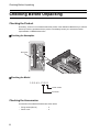
Checking Before Unpacking
Checking Before Unpacking
Checking the Product
On delivery, be sure to check that the delivered product is the 3G3AX-PG Board that you ordered.
Should you find any problems with the product, immediately contact your nearest local sales
representative or OMRON sales office.
Checking the Nameplate
Nameplate
C
D
D
PG01 19208 A
Checking the Model
3G3AX-PG01
Serial number
PG Board
Checking the Accessories
Accessories of the 3G3AX-PG Board are shown below.
•
•
8
Fixing screws (M3 x 8)
Ferrite cores
: 2
: 2
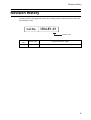
Revision History
Revision History
A manual revision code appears as a suffix to the catalog number located at the lower left of the
front and back covers.
Cat.No.
I564-E1-01
Revision code
Revision
code
Revision date
01
April 2008
Changes and revision pages
First printing
9
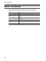
About This Manual
About This Manual
This User's Manual is compiled chapter by chapter for user's convenience as follows:
Understanding the following configuration ensures more effective use of the product.
Chapter
10
Overview
Chapter 1
Overview
Describes the functional block diagram of the product.
Chapter 2
Design
Describes the mounting method of the product, terminal names, and
wiring.
Chapter 3
Operation
Describes the parameters related to the product and precautions for
operation.
Chapter 4
Functions
Describes the parameter functions.
Chapter 5
Maintenance
Operations
Describes the causes and their countermeasures if the Inverter fails.
Chapter 6
Specifications
Describes the product specifications.
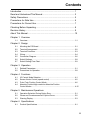
Contents
Introduction..............................................................................................1
Read and Understand This Manual.........................................................2
Safety Precautions ..................................................................................5
Precautions for Safe Use.........................................................................6
Precautions for Correct Use ....................................................................7
Checking Before Unpacking ....................................................................8
Revision History.......................................................................................9
About This Manual...................................................................................10
Chapter 1 Overview
1-1
Overview..................................................................................................1-1
Chapter 2 Design
2-1
2-2
2-3
2-4
2-5
2-6
2-7
Mounting the PG Board ...........................................................................2-1
Terminal Arrangement .............................................................................2-2
Terminal Functions ..................................................................................2-3
Wiring.......................................................................................................2-4
Connection Diagram ................................................................................2-6
Switch Settings ........................................................................................2-8
Switch Setting Flow Chart........................................................................2-9
Chapter 3 Operation
3-1
3-2
Related Parameters.................................................................................3-1
Precautions for Operation........................................................................3-8
Chapter 4 Functions
4-1
4-2
4-3
4-4
V2 Control Mode Selection ......................................................................4-1
Sensor Vector Control (speed control) ....................................................4-2
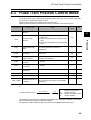
Pulse Train Position Control Mode ..........................................................4-6
Absolute Position/High-resolution Absolute Position
Control Modes .........................................................................................4-15
Chapter 5 Maintenance Operations
5-1
5-2
5-3
Operation Selection During Option Error .................................................5-1
Cause and Countermeasure of Option Errors .........................................5-2
Warning Display.......................................................................................5-3
Chapter 6 Specifications
6-1
Product Specifications .............................................................................6-1
11
Contents
12
Chapter 1
Overview
1-1 Overview ........................................................... 1-1
1-1 Overview
1Overview
1-1 Overview
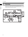
The PG Board (3G3AX-PG01) is an optional board for the 3G3RX Series Inverter.
With this board, you can realize highly accurate system operation with minimum speed fluctuation,
and position control via pulse train position command input by detecting the rotation speed of the
motor with an encoder and using the data for feedback.
Overview
1
Inverter
LAC
Internal
settings
Position
control
LAD
Speed
control
Torque
limit
TH
Current
control
PWM
M
PCLR
Rotation
speed
detection
POK
ORT
STAT
Orientation
control
Excessive speed
deviation signal
output
0 Hz
signal
3G3AX-PG
Position
detection
EAP,EAN
EBP,EBN
EZP,EZN
EP5,EG5
AP,AN
BP,BN
SAP,SAN
SBP,SBN
DSE
1-1
ZS
EC
Chapter 2
Design
2-1
2-2
2-3
2-4
2-5
2-6
2-7
Mounting the PG Board ................................... 2-1
Terminal Arrangement..................................... 2-2
Terminal Functions .......................................... 2-3
Wiring ................................................................ 2-4
Connection Diagram ........................................ 2-6
Switch Settings ................................................ 2-8
Switch Setting Flow Chart ............................... 2-9
2-1 Mounting the PG Board
2Design
2-1 Mounting the PG Board
Securely mount the PG Board as shown below.
Place the four holes (in the corners) and the connector (on the back) of the PG Board on Board port
1 (or port 2) correctly, with the two holes on the guideposts and the other two on the screw holes.
Design
2
The PG Board
Guideposts for positioning
the PG Board
Board port 1
Board port 2
Fixing screw holes
for the PG Board (M3 screw)
Guideposts for positioning
the PG Board
To mount the PG Board, be sure to tightly fix it with the two provided fixing screws after putting in
place the connector securely. Otherwise, the Inverter will not operate properly.
2-1
2-2 Terminal Arrangement
2-2 Terminal Arrangement
The terminal arrangement on the PG Board is shown below.
2
DIP switch
SWENC
Design
DIP switch
SWR
Connector
to the Inverter
TM1
TM2
TM1 terminal arrangement
EP5 EG5 EAP EAN EBP EBN EZP EZN
TM2 terminal arrangement
SAP SAN SBP SBN AP AN
BP
BN
2-2
2-3 Terminal Functions
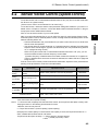
2-3 Terminal Functions
Input terminal
Terminal symbol
Output terminal
Design
2
Terminal
name
Functions
•Pulse train mode selection (P013)*1
Mode 0: Pulse train with 90° phase difference
Mode 1: Forward/Reverse command + Pulse train
5V DC Receiver input
Mode 2: Forward pulse train + Reverse pulse train
(Complies with RS-422)
•Built-in termination resistor can be set enabled or
disabled using the DIP switch on the PG Board.
(Built-in termination resistance: 150Ω)
SAP
SAN
SBP
SBN
Pulse train
position
command
input
EAP
EAN
EBP
EBN
EZP
EZN
Encoder
signal
input
A, B, Z: Encoder signal input
Photocoupler input
(Compatible with the rotary
encoder of 5V DC line driver
output type)
AP
AN
BP
BN
Encoder
signal
output
Outputs the encoder signal input by the pulse ratio
(1:1).
5V DC line driver output
(Complies with RS-422)
EP5
EG5
(Common)
Encoder
power
supply
+5 V DC power supply
150 mA max.
*1 Use the Inverter parameters for the pulse train mode selection.
2-3
Electric specifications
2-4 Wiring
2-4 Wiring
2
Wiring Length of Encoder Cable
To use a relay amplifier, the wiring length between the PG Board and the relay amplifier must be
within 20 m. Check the input specifications of the relay amplifier to determine the wiring length between the relay amplifier and encoder. (Confirm with the relay amplifier manufacturer.)
If the wiring length is longer than that specified, the Inverter could work erroneously due to influence from the outside noise at that point. Be careful of the relay amplifier wiring.
The encoder cable could be easily influenced by outside noise depending on the shielding method
of the shield cable, resulting in an Inverter failure. Generally connect to the power supply ground
of a signal line or to the ground for shielding. (To connect to the ground, be careful of the ground
cabling route and avoid multi-point grounding.)
To use a PG Board encoder power supply for the interface power supply between the PG Board
and relay amplifier, adopt a shielding method following "Mounting the Ferrite Cores" (page 2-5). A
different method can be applied, however, for the power supply from a source other than the PG
Board. If using a relay amplifier, also follow "Mounting the Ferrite Cores" (page 2-5) for the connection of the ferrite cores.
2-4
Design
Do not exceed 20 m for the wiring length of the encoder cable. If the wiring length should be 20 m
or longer by necessity, use a relay amplifier that specifies 5 V line driver output. In this case, be
careful of the following points for wiring.
2-4 Wiring
Mounting the Ferrite Cores
The ferrite core mounting method is shown below.
Mount the two provided ferrite cores as below when connecting the encoder cable.
Connect the wire to the EG5 terminal of the 3G3AX-PG Board through the ferrite cores for shielding.
2
Design
3G3AX-PG
Ferrite cores
Encoder cable (Shield wire)
If the ferrite cores cover the shield coating, they fail to work effectively, causing the Inverter to malfunction. Be sure to fix the ferrite cores or take other appropriate measures so that they do not overlap the shield coating.
The shield wire connected to the terminal could become disconnected due to the weight of the ferrite
cores. Be sure to fix the ferrite cores or take other appropriate measures so that the shield wire does
not receive the weight of the ferrite cores.
2-5
2-5 Connection Diagram
2-5 Connection Diagram
Available to assign to
multi-function input
terminals 1 to 8
2
PG Board
Inverter control terminal
Encoder signal
EP5
RV
Input
terminal
EG5
LAC (LAD cancel)
(Position deviation
PCLR clear)
ORT (Orientation)
POK
ZS
DSE
Available to assign to
multi-function output
terminals 1 to 5
M
EAP
EAN
TM1
STAT (Pulse train position
CM1 command input
permission)
Output
terminal
Design
FW
EBP
EBN
EZP
EZN
(Position ready)
EC
(0 Hz signal)
(Excessive speed
deviation)
Motor with
an encoder
FS
SAP
FV
SAN
FC
SBP
TM2
Pulse train
position command
SBN
AP
AN
BP
Encoder signal output
BN
Note 1: For the terminal connection on the Inverter, refer to the Inverter 3G3RX User’s Manual.
Note 2: For the signal line, use a twisted shield wire and apply the shield coating as illustrated below. Keep the length to 20 m or less. If the wiring length should be 20 m or more by necessity, use a VX application control device RCD-E(remote control device), or CVD-E
(insulated type signal converter). For the encoder line, use a twisted shield wire of 0.75 mm2
or more. Keep the length to 20 m or less. If the wiring length should be 20 m or longer by
necessity, use a relay amplifier that specifies 5 V line driver output.
Perform insulating treatment.
Ground connection is not required.
Connect to each common
terminal on the PG Board.
2-6
2-5 Connection Diagram
Note 3: Separate the wiring from that of the main circuit and/or the relay control circuit. If they have
to be crossed, be sure to cross them at right angles.
2
Design
Main circuit
power cable
R/L1, S/L2, T/L3, U/T1, V/T2, W/T3,
P/+2, PD, RB, N/-, Ro, To etc.
Cross at right angles
I/O signal lines
Control signals including STAT, ORT, LAC,
PCLR, SAP, SAN, SBP, SBN, EAP, EAN,
EBP, EBN, POK, DSE, ZS, AP, AN, BP, BN,
FC, EP5, EG5, CM1, CM2, P24 and PLC
Separate them 10 cm apart or more
Note 4: Do not short-circuit between the terminals EP5 and EG5 in order to avoid breakage.
Note 5: Insulate between the analog input common terminal “FC” of the Inverter and the common
terminal (common) for the encoder signal and such peripheral devices as a sequencer.
Note 6: To connect the encoder signal line, follow the illustration below for phase relations during
the rotation of the motor.
EAP
EAN
EBP
EBN
EZP
EZN
2-7
2-6 Switch Settings
2-6 Switch Settings
2
Switch Arrangement
The switch arrangement is shown below.
Design
SWENC
SWR
Switch [ON/OFF] setting
O
F
F
TM1
TM2
1
2
Slide the switch from left (OFF) to
right to turn it ON.
Default Settings
The default settings (factory settings) are shown below.
DIP switch
name
Switch No.
Settings
ON
Disconnection detection enabled when encoder A
and B phases are not connected
OFF
Disconnection detection disabled when encoder A
and B phases are not connected
ON
Disconnection detection enabled when encoder Z
phase is not connected
OFF
Disconnection detection disabled when encoder Z
phase is not connected
ON
Built-in termination resistor between SAP and
SAN (150 Ω) enabled
OFF
Built-in termination resistor between SAP and
SAN disabled
ON
Built-in termination resistor between SBP and
SBN (150 Ω) enabled
OFF
Built-in termination resistor between SBP and
SBN disabled
1
SWENC
2
1
SWR*1
2
Default
setting
OFF
OFF
OFF
OFF
*1 When connecting the multiple units in parallel for pulse train position command inputs, turn ON
the SWR1 and SWR2 of the only one unit located farthest from the master unit.
2-8
2-7 Switch Setting Flow Chart
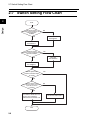
2-7 Switch Setting Flow Chart
2
Design
Start
Will disconnection
detection of the encoder A and B
phases signal be
enabled?
NO
Turn OFF
the SWENC1.
YES
Turn ON
the SWENC1.
Will disconnection
detection of the encoder Z phase
signal be enabled?
NO
Turn OFF
the SWENC2.
YES
Turn ON
the SWENC2.
Will the pulse train
position command input
be used?
NO
YES
Will the multiple units
for pulse train position command
inputs be connected
in parallel?
NO
YES
Turn ON the SWR1 and 2 of
the only one unit that is
farthest from the master unit.
End
2-9
Turn ON the SWR1 and 2.
Chapter 3
Operation
3-1 Related Parameters.......................................... 3-1
3-2 Precautions for Operation............................... 3-8
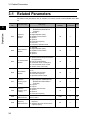
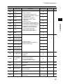
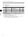
3-1 Related Parameters
3Operation
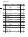
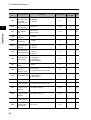
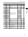
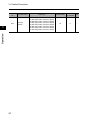
3-1 Related Parameters
For details on the parameters, refer to "Chapter 4 Functions" and the Inverter 3G3RX User’s Manual.
Parameter
No.
Default setting
(3G3RX-)
Changes during operation
Unit
Frequency
reference
selection
00: Digital Operator (FREQ adjuster)
(Enabled when 3G3AX-OP01 is
connected.)
01: Terminal
02: Digital Operator (F001)
03: ModBus communication
04: Option 1
05: Option 2
06: Pulse train frequency
07: Not used
10: Frequency operation result
02
×
−
RUN command
selection
01: Terminal
02: Digital Operator (F001)
03: ModBus communication
04: Option 1
05: Option 2
02
×
−
V/f characteristics
selection
00: Constant torque characteristics (VC)
01: Special reduced torque characteristics (special VP)
02: Free V/f characteristics
03: Sensorless vector control (SLV)
04: 0-Hz sensorless vector control
05: Sensor vector control (V2)
00
×
−
A076
PID feedback
selection
00: FI
01: FV
02: RS485 communication
03: Pulse train frequency
10: Operation function output
00
×
−
A141
Operation
frequency input
A setting
02
×
−
A142
Operation
frequency Input
B setting
03
×
−
A145
Frequency
addition amount
0.00 to 99.99
100.0 to 400.0
0.00
×
Hz
A146
Frequency
addition direction
00: Adds the A145 value to the output
frequency
01: Subtracts the A145 value from the
output frequency
0.0
×
−
Function name
Operation
3
A001
A002
A044
3-1
Data range
00: Digital Operator (F001)
01: Digital Operator (FREQ adjuster)
(Enabled when 3G3AX-OP01 is
connected.)
02: Input FV
03: Input FI
04: RS485 communication
05: Option 1
06: Option 2
07: Pulse train frequency
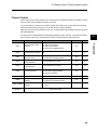
3-1 Related Parameters
Parameter
No.
Function name
C001
Multi-function input 1
selection
C002
Multi-function input 2
selection
C003
Multi-function input 3
selection
C004
Multi-function input 4
selection
C005
Multi-function input 5
selection
C006
Multi-function input 6
selection
C007
Multi-function input 7
selection
C008
Multi-function input 8
selection
C021
Multi-function output
terminal P1 selection
00
C022
Multi-function output
terminal P2 selection
01
C023
Multi-function output
terminal P3 selection
C024
Multi-function output
terminal P4 selection
C025
Multi-function output
terminal P5 selection
40
C026
Relay output (MA,
MB) function selection
05
H001
Auto-tuning selection
00: Disabled
01: Not rotate
02: Rotate
H002
Motor parameter
selection
00: Standard motor parameter
01: Auto-tuning parameter
02: Auto-tuning parameter
(Online auto-tuning enabled)
H003
Motor capacity
selection
0.20 to 75.00
H004
Motor pole
number selection
2/4/6/8/10
H005
Speed response
H006
H020
Data range
Default setting
Changes during operation
Unit
01
45: ORT (orientation)
47: PCLR (position deviation clear)
48: STAT (pulse train position command
input permission)
50: ADD (frequency addition)
52: ATR (torque reference input
permission)
54: SON (servo ON)
66: CP1 (position command selection 1)
67: CP2 (position command selection 2)
68: CP3 (position command selection 3)
69: ORL (zero return limit signal)
70: ORG (zero return startup signal)
71: FOT (forward driving stop)
72: ROT (reverse driving stop)
73: SPD (speed/position switching)
18
12
3
02
×
−
×
−
00
×
−
00
×
−
Default setting
×
kW
4
×
Pole
0.001 to 9.999/10.00 to 80.00
(10.000 to 80.000)
1.590
{
−
Stabilization
parameter
0. to 255.
100.
{
−
Motor parameter
R1
0.001 to 9.999
10.00 to 65.53
Depends on the
motor capacity.
×
Ω
Operation
03
04
05
06
21: ZS (0-Hz signal)
22: DSE(excessive speed deviation)
23: POK (position ready)
03
07
3-2
3-1 Related Parameters
Parameter
No.
Operation
3
Function name
Data range
Default setting
Changes during operation
Unit
H021
Motor parameter
R2
0.001 to 9.999
10.00 to 65.53
Depends on the
motor capacity.
×
Ω
H022
Motor parameter
L
0.01 to 99.99
100.0 to 655.3
Depends on the
motor capacity.
×
mH
H023
Motor parameter
Io
0.01 to 99.99
100.0 to 655.3
Depends on the
motor capacity.
×
A
H024
Motor parameter
J
0.001 to 9.999
10.00 to 99.99
100.0 to 999.9
1000. to 9999.
Depends on the
motor capacity.
×
kgm2
H030
Motor parameter
R1
(auto-tuning data)
0.001 to 9.999
10.00 to 65.53
Depends on the
motor capacity.
×
Ω
H031
Motor parameter
R2
(auto-tuning data)
0.001 to 9.999
10.00 to 65.53
Depends on the
motor capacity.
×
Ω
H032
Motor parameter
L
(auto-tuning data)
0.01 to 99.99
100.0 to 655.3
Depends on the
motor capacity.
×
mH
H033
Motor parameter
Io
(auto-tuning data)
0.01 to 99.99
100.0 to 655.3
Depends on the
motor capacity.
×
A
H034
Motor parameter
J
(auto-tuning data)
0.001 to 9.999
10.00 to 99.99
100.0 to 999.9
1000. to 9999.
Depends on the
motor capacity.
×
kgm2
H050
PI proportional
gain
0.0 to 999.9
1000.
100.0
{
−
H051
PI integral gain
0.0 to 999.9
1000.
100.0
{
−
H052
P proportional
gain
0.01 to 10.00
1.00
{
−
H060
Limit at 0 Hz
0.0 to 100.0
100.0
{
%
H061
Boost amount at
SLV startup, 0 Hz
0. to 50.
50.
{
%
H070
For PI proportional
gain switching
0.0 to 999.9
1000.
100.0
{
−
H071
For PI integral
gain switching
0.0 to 999.9
1000.
100.0
{
−
H072
For P proportional
gain switching
0.00 to 10.00
1.00
{
−
H073
Gain switching
time
0. to 9999.
100.
{
ms
3-3
3-1 Related Parameters
Parameter
No.
Function name
Data range
Default setting
Changes during operation
Unit
Operation
selection at
option 1 error
00: Trip
01: Continues operation
00
×
−
P002
Operation
selection at
option 2 error
00: Trip
01: Continues operation
00
×
−
P011
Encoder pulses
128. to 9999.
1000 to 6500 (10000 to 65000)
1024.
×
Pulse
P012
V2 control mode
selection
00: ASR (speed control mode)
01: APR (pulse train position control
mode)
02: APR2 (absolute position control
mode)
03: HAPR (high-resolution absolute
position control mode)
00
×
−
P013
Pulse train mode
selection
00: Mode 0
01: Mode 1
02: Mode 2
00
×
−
P014
Orientation stop
position
0. to 4095.
0.
×
−
P015
Orientation speed
setting
Starting frequency to Max. frequency
(Upper limit 120.0)
5.00
×
Hz
P016
Orientation direction
setting
00: Forward side
01: Reverse side
00
×
−
P017
Position ready
range setting
0. to 9999.
1000 (10000)
5.
×
Pulse
P018
Position ready
delay time setting
0.00 to 9.99
0.00
×
s
P019
Electronic gear
setting position
selection
00: Position feedback side (FB)
01: Position command side (REF)
00
×
−
P020
Electronic gear
ratio numerator
0. to 9999.
1.
×
−
P021
Electronic gear
ratio denominator
0. to 9999.
1.
×
−
P022
Position control
feed forward gain
0.00 to 99.99
100.0 to 655.3
0.00
×
−
P023
Position loop gain
0.00 to 99.99
100.0
0.50
×
rad/s
P024
Position bias
amount
−204 (−2048.) / −999. to 2048.
0.
{
−
3-4
3
Operation
P001
3-1 Related Parameters
Operation
3
Parameter
No.
Function name
Default setting
Changes during operation
Unit
P025
Secondary resistance compensation enable/
disable selection
00: Disabled
01: Enabled
00
×
−
P026
Overspeed error
detection level
0.0 to 150.0
135.0
×
%
P027
Speed deviation
error detection
level
0.00 to 99.99
100.0 to 120.0
7.50
×
Hz
P028
Motor gear ratio
numerator
1. to 9999.
1.
×
−
P029
Motor gear ratio
denominator
1. to 9999.
1.
×
−
P031
Acceleration/
deceleration time
input type
00: Digital Operator
01: Option 1
02: Option 2
00
×
−
P032
00: Digital Operator
Orientation stop
01: Option 1
position input type
02: Option 2
00
×
−
P033
Torque reference
input selection
00: Terminal FV
01: Terminal FI
02: Terminal FE
03: Digital Operator
00
×
−
P034
Torque reference
setting
0. to 200.
0.
{
%
P035
Polarity selection
at torque
reference via FE
00: As per sign
01: Depends on the RUN direction
00
×
−
P036
00: Disabled
Torque bias mode 01: Digital Operator
02: Terminal FE
00
×
−
P037
Torque bias value
−200. to +200.
0.
{
%
P038
Torque bias
polarity selection
00: As per sign
01: Depends on the RUN direction
00
×
−
P039
Speed limit value
in torque control
(forward)
0.00 to Max. frequency
0.00
{
Hz
P040
Speed limit value
in torque control
(reverse)
0.00 to Max. frequency
0.00
{
Hz
P055
Pulse train
frequency scale
1.0 to 50.0
25.0
×
kHz
P056
Pulse train
frequency filter
time constant
0.01 to 2.00
0.10
×
s
3-5
Data range
3-1 Related Parameters
Parameter
No.
Function name
Data range
Default setting
Changes during operation
Unit
0.
×
%
100.
×
%
Pulse train
frequency bias
amount
−100. to +100.
P058
Pulse train
frequency limit
0. to 100.
P060
Multi-step position
command 0
0
P061
Multi-step position
command 1
0
P062
Multi-step position
command 2
0
P063
Multi-step position
command 3
P064
Multi-step position
command 4
P065
Multi-step position
command 5
0
P066
Multi-step position
command 6
0
P067
Multi-step position
command 7
0
P068
Zero return mode
00: Low
01: Hi1
02: Hi2
P069
Zero return
direction selection
00: Forward side
01: Reverse side
P070
Low-speed zero
return frequency
P071
Position range specification (reverse
side) to Position range specification
(forward side)
(Displays MSB 4 digits including “−”)
3
0
{
−
00
{
−
00
{
−
0.00 to 10.00
0.00
{
Hz
High-speed zero
return frequency
0.00 to 99.99
100.0 to Max. frequency
0.00
{
Hz
P072
Position range
specification
(forward side)
0 to 268435455 (at P012 = 02)
0 to 1073741823 (at P012 = 03)
(Displays MSB 4 digits)
268435455
{
−
P073
Position range
specification
(reverse side)
−268435455 to 0 (at P012 = 02)
−1073741823 to 0 (at P012 = 03)
−268435455
{
−
(Displays MSB 4 digits)
0
3-6
Operation
P057
3-1 Related Parameters
Parameter
No.
P074
Operation
3
3-7
Function name
Teaching
selection
Data range
Default setting
Changes during operation
Unit
00: Multi-step position command 0 (P060)
01: Multi-step position command 1 (P061)
02: Multi-step position command 2 (P062)
03: Multi-step position command 3 (P063)
04: Multi-step position command 4 (P064)
05: Multi-step position command 5 (P065)
06: Multi-step position command 6 (P066)
07: Multi-step position command 7 (P067)
00
{
−
3-2 Precautions for Operation
3-2 Precautions for Operation
Operation
For operation, refer to “Chapter 3 Operation” of the Inverter 3G3RX User’s Manual. When operating
the RUN command from the terminal block side of the Inverter, follow the procedure below.
Test Run
Check the following items for a test run.
• Does the motor accelerate normally?
• Is the motor rotation direction correct?
• Is there any abnormal vibration or noise in the motor?
Check whether the phase sequence is correct if the motor does not accelerate normally or an Inverter overload trip is observed in the test run. If the waveform of phase A is 90° ahead of that of
phase B in forward rotation, the phase sequence can be said to be normal.
Note 1: In some cases, monitor signal is not output from the “MP” terminal of Inverter if the Inverter
runs without the motor connected and with the control method set to “05” (sensor vector
control) in the Inverter function mode “A044”. With “05” set, check the motor output after
connecting the motor with an encoder.
Note 2: Do not perform free running through the RS terminal allocated to the multifunction input of
the Inverter during operation. Otherwise, an overcurrent trip or power element breakage
may occur. Use the FRS terminal allocated to the multifunction input of the Inverter for free
running during operation.
Note 3: With a large value set for torque limit (b041 - b044), an overcurrent trip may occur during
load application. Adjust the torque limit set value to avoid this.
Note 4: Perform auto tuning if the motor parameter is unknown.
3-8
Operation
1. Supply power to the Inverter.
2. Set the V/f characteristics selection (A044) to “05”.
3. Set the necessary items according to “Chapter 4 Functions” of the Inverter 3G3RX
User’s Manual.
4. For speed control, operation starts according to each setting when the Inverter RUN
command is turned ON.
5. For position control, turn ON the STAT terminal, and turn ON the Inverter RUN command. When inputting the pulse train position command between SAP and SAN,
and between SBP and SBN, the motor rotates according to the input pulse.
3
3-2 Precautions for Operation
Note 5: If vector control cannot provide the desired characteristics, adjust the motor parameters
depending on the phenomenon, according to the table below.
Operation status
Adjustment method
Adjustment item
Reduce motor parameter J from the set
parameter.
H024/H034
During startup
Shock occurs during startup.
During
deceleration
Motor hunting occurs.
During torque limit
Insufficient torque occurs at
low frequency during torque
limit
Set an overload limit level lower than
the torque limit level.
b021
b041 to b044
Low-frequency
operation
Rotation is not constant.
Increase motor parameter J from the
set parameter.
H024/H034
High-frequency
operation
Torque reduction occurs at
high frequency.
Decrease motor parameter Io. (to approx. 0.7 times)
H023
3
Operation
Phenomenon
3-9
Reduce the speed response.
Reduce motor parameter J from the set
parameter.
H005
H024/H034
Chapter 4
Functions
4-1
4-2
4-3
4-4
V2 Control Mode Selection.............................. 4-1
Sensor Vector Control (speed control) .......... 4-2
Pulse Train Position Control Mode ................ 4-6
Absolute Position/High-resolution
Absolute Position Control Modes .................. 4-15
4-1 V2 Control Mode Selection
4Functions
4-1 V2 Control Mode Selection
Select a control method in V2 control mode selection P012.
When “00” (ASR) is selected in P012, speed control mode is enabled. Select a frequency reference
in frequency reference selection A001.
When “01” (APR) is selected in P012, the Inverter enables position control by generating frequency
reference based on the position command pulse input from the pulse train position command input
terminal, and on the position feedback detected by the encoder.
4
Functions
Select any of the three pulse train position command input modes in pulse train mode selection
P013.
To perform pulse train position control, allocate “48” (STAT) to any of the multi-function input terminals. While the STAT terminal is tuned on, pulse train position command input is accepted.
Position deviation can be cleared through external input. Allocate “47” (PCLR) to any of the multifunction input terminals. Turning ON/OFF the PCLR terminal can clear position deviation data.
Allocating “22” (DSE) to any of the multi-function output terminals enables excessive speed deviation signal output.
Set a deviation level in speed deviation error detection level P027. When the deviation between real
frequency and reference frequency exceeds the P027 set value, the DSE signal turns on.
When “02” (APR2) or “03” (HAPR) is selected in P012, the Inverter performs absolute position control with reference to the absolute position from its origin.
Parameter No.
Function name
Data
Default
setting
Unit
00
−
P012
00: ASR (speed control mode)
01: APR (pulse train position control mode)
V2 control mode selection 02: APR2 (absolute position control mode)
03: HAPR (high-resolution absolute position
control mode)
P011
Encoder pulses
128. to 9999./1000 to 6553
(10000 to 65535):
Number of encoder pulses
1024.
Pulse
P023
Position loop gain
0.00 to 99.99/100.0: Position loop gain
0.50
rad/s
P027
Speed deviation error
detection level
0.00 to 99.99/100.0 to 120.0:
DSE signal output level
7.50
Hz
H004
Motor pole number
selection
2/4/6/8/10: Select a motor pole number.
4
Pole
C001 to C008
Multi-function inputs 1 to 8
selection
47: PCLR (position deviation clear)
48: STAT (pulse train position command input permission)
−
−
C021 to C025
Multi-function output terminals P1 to P5 selection
C026
Relay output (MA, MB)
function selection
Related functions
4-1
−
−
22: DSE (excessive speed deviation)
05
A001, P013
4-2 Sensor Vector Control (speed control)
4-2
Sensor Vector Control (speed control)
To use this function, set V/f characteristics selection A044 to “05” (V2), and V2 control mode selection P012 to “00” (speed control).
(“Sensor vector control” can be selected for 1st control only.)
To use this function, make sure that the motor parameter settings are suitable for your motor. For
details, refer to “Chapter 4 Functions, 4-2 Function Mode, Moter Parameter Selection” in the general-purpose Inverter 3G3RX User’s Manual.
Also, be sure to set the number of your encoder pulses.
Operation
status
Phenomenon
Adjustment method
During
startup
Shock occurs during
startup.
During
deceleration
Motor hunting occurs.
During torque
limit
Insufficient torque at low
frequency during torque
limit
Set an overload limit level lower than the torque limit
level.
Low-frequency operation
Rotation is not constant.
Increase motor parameter J from the set parameter.
Related functions
Reduce motor parameter J from the set parameter.
Reduce the speed response.
Reduce motor parameter J from the set parameter.
Adjustment item
H024/H034
H005
H024/H034
b021
b041 to b044
H024/H034
A001, A044, F001, b040 , H002, H003, H004 , H020 , H021 , H022 , H023 ,
H050 , H051 , H052 , P011, P012
Note 1: Make sure that the carrier frequency (b083) is not lower than 2.1 kHz. If the carrier frequency is at 2.1 kHz or
lower, the Inverter will not operate normally.
Note 2: To use a motor with a capacity lower than that of the Inverter, set a torque limit value (b041 to b044), while
keeping the value α in the following formula at 200% or lower.
Otherwise, the motor may burn out.
α = Torque limit set value × (Inverter capacity) / (Motor capacity)
(Example) If the Inverter capacity is 0.75 kW and the motor capacity is 0.4 kW, the torque limit set value for α =
200%, calculated with the above formula, is as follows:
Torque limit set value (b041 to b044) = α × (Motor capacity) / (Inverter capacity)
= 200% × (0.4 kW) / (0.75 kW) = 106%
4-2
4
Functions
With V2 control mode selection P012, you can select four types of control modes: Speed control,
Pulse train position control, Absolute position control, and High-resolution absolute position control.
Note the following before use:
• Sufficient characteristics may not be obtained if you select a motor size two or more ranks lower
than the motor size specified.
• If the Inverter does not normally accelerate, or if overload protection is activated, check the phase
sequence of the encoder signal. (If phase A is advanced by 90° from phase B during forward
run, it is judged as being normal.)
When running the Inverter with V/f characteristics selection A044 set to “00” (VC), you can
check the rotation direction with real frequency monitor d008.
(If positive frequency is detected when the forward command is activated, or if negative frequency is detected when the reverse command is activated, the rotation direction is judged as
being normal.)
If sensor vector control cannot provide the desired characteristics, adjust the motor parameters depending on the phenomenon, as shown in the table below.
4-2 Sensor Vector Control (speed control)
Torque Bias Function
This function applies bias to the torque reference generated in speed control, and is useful for elevating
applications.
Parameter No.
Functions
4
Function name
Data
Default setting
Unit
P036
Torque bias mode
00: Disabled
01: Set via the Digital Operator
02: Set via terminal FE *1
00
−
P037
Torque bias value
−200 to +200: Enabled when P036 = 01
0.
%
P038
Torque bias polarity
selection *2
00: As per sign
01: Depends on the RUN direction
00
−
Related
functions
d010
*1. When torque bias is set to the FE terminal, −10 to +10 (V) is recognized as −200 to +200 (%).
*2. • When “00” (As per sign) is selected:
When the polarity of a torque bias signal is (+), the torque increases for forward rotation, and when it is (−), the
torque increases for reverse rotation, regardless of the RUN direction.
• When “01” (Depends on the RUN direction) is selected:
The torque bias signal polarity and torque bias direction vary depending on the RUN command direction.
Forward command: Applies torque in the same direction as the torque bias.
Reverse command: Applies torque in the opposite direction of the torque bias.
4-3
4-2 Sensor Vector Control (speed control)
Torque Control
This function can be used in torque control, as well as in the speed and pulse train position controls.
Torque control can be applied to winders, and more.
To run the Inverter in torque control mode, allocate “52” (ATR) to any of the multi-function inputs.
While the ATR terminal is turned on, the torque reference input is enabled.
With torque reference input selection P033, you can select either each analog input or the input via
the Digital Operator.
The torque control speed depends on the balance between torque and load. To prevent the Inverter
from running out of control, set a speed limit value in P039 (forward) or P040 (reverse).
Parameter No.
Function name
Data
Default setting
Unit
00: Input via terminal FV
01: Input via terminal FI
02: Input via terminal FE
03: Input via the Digital Operator
00
−
P034
Torque reference setting
0 to 200: Torque reference when P033 =
03
0.
%
P035
Polarity selection at torque
reference via FE
00: As per sign
01: Depends on the RUN direction
00
−
P039
Speed limit value in torque
control (forward)
0.00 to 99.99/100.0 to 400.0
0.00
Hz
P040
Speed limit value in torque
control (reverse)
0.00 to 99.99/100.0 to 400.0
0.00
Hz
P036
Torque bias mode
00: Disabled
01: Set via the Digital Operator
02: Set via terminal FE
00
−
P037
Torque bias value
−200 to +200: Enabled when P036 = 01
0.
%
P038
Torque bias polarity
selection
00: As per sign
01: Depends on the RUN direction
00
−
Multi-function inputs 1 to 8
selection
52: ATR (torque reference input permission)
−
−
C001 to C008
Related
functions
d009, d010, d012
4-4
Functions
P033
Torque reference input
selection
4
4-2 Sensor Vector Control (speed control)
Control Block Diagram
Torque bias
Torque limit
ATR terminal
Torque reference
(Reference value for current control)
Torque reference input
Speed control
(P control)
4
Speed
monitor
Speed limit
value
Functions
Speed detection
value
4-5
The speed control (P control) operates when a
speed detection value exceeds the limit value.
4-3 Pulse Train Position Control Mode
4-3 Pulse Train Position Control Mode
To use this function, set V/f characteristics selection A044 to “05” (V2), and V2 control mode selection P012 to “01” (pulse train position control).
(“Sensor vector control” can be selected for 1st control only.)
Select a pulse train position command input mode in pulse train mode selection P013.
Parameter No.
Function name
Default
setting
Data
01: APR (pulse train position control mode)
P013
Pulse train mode
selection
00: Mode 0 (pulse train with 90° phase
difference)
01: Mode 1 (forward/reverse command + Pulse
train)
02: Mode 2 (Forward pulse train + Reverse pulse
train)
P017
Position ready range
setting
0. to 9999./1000 (10000):
Set a value equivalent to encoder ×4
multiplication.
P018
Position ready delay
time setting
0.00 to 9.99
P019
Electronic gear setting
position selection
P020
4
00
−
5.
−
0.00
s
00: FB (feedback side)
01: REF (command side)
00
−
Electronic gear ratio
numerator
1. to 9999.
1.
−
P021
Electronic gear ratio
denominator
1. to 9999.
1.
−
P022
Position control feed
forward gain
0.00 to 99.99/100.0 to 655.3
0.00
−
P023
Position loop gain
0.00 to 99.99/100.0
0.50
rad/s
P024
Position bias amount
−204 (−2048)/−999. to 2048.
0.
−
Multi-function inputs 1 to
8 selection
47: PCLR (position deviation clear)
48: STAT (pulse train position command input
permission)
−
−
C001 to C008
Frequency reference for the pulse train position control mode is calculated with the following formula:
Frequency reference (Hz) =
6.4 × P × Kv
ENC
×
ΔP
255
P
Kv
ENC
ΔP
: Number of motor poles
: Position loop gain
: Number of encoder pulses
: Position deviation
In the position control mode, the acceleration/deceleration time settings are disabled. (The Inverter
will be automatically brought into LAD cancel status.)
The higher the position loop-back gain, the shorter the acceleration/deceleration time.
4-6
Functions
V2 control mode
selection
P012
Unit
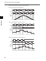
4-3 Pulse Train Position Control Mode
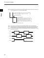
For details on the pulse train input mode, refer to the following.
•Mode 0: pulse train with 90° phase difference
SAP
SAN
(Pulse train input)
SBP
SBN
(Pulse train input)
Detected
pulses
4
Forward
Reverse
Functions
Time
•Mode 1: Forward/Reverse command + Pulse train
SAP
SAN
(Pulse train input)
SBP
SBN
(Forward/Reverse command)
Detected
pulses
Forward
Reverse
Time
•Mode 2: Forward pulse train + Reverse pulse train
SAP
SAN
(Forward pulse train input)
SBP
SBN
(Reverse pulse train input)
Detected
pulses
Forward
Reverse
Time
4-7
4-3 Pulse Train Position Control Mode
Electronic Gear Function
This function allows you to set a gain relative to position command or position feedback and to
change the main/sub motor rotation ratio, particularly for synchronous operation.
Parameter No.
Function name
Data
Default setting
Unit
Electronic gear setting
position selection
00: Position feedback side (FB)
01: Position command side (REF)
00
−
P020
Electronic gear ratio
numerator *3
1 to 9999
1.
−
P021
Electronic gear ratio
denominator *3
1 to 9999
1.
−
P022
Position control
feedforward gain *1
0.00 to 655.3
0.00
−
P023
Position loop gain *2
0.00 to 99.99/100.0
0.50
rad/s
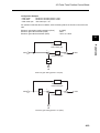
Note: Below are the block diagrams of the electronic gear function.
First-order lag filter
1
1+sT
Position control
feedforward gain
P022
Position loop gain
P019=00 (FB)
Position
command
Speed
command
P023
N
D
Electronic gear
Position feedback
First-order lag filter
1
1+sT
P019=01 (REF)
Electronic gear
Position
N
command
D
Position control
feedforward gain
P022
Position loop gain
P023
Speed
command
Position feedback
*1.
*2.
*3.
It is recommended that position control feedfoward gain adjustment should be started with P022 = 2.00. To
reduce the position deviation between the main and sub motors, increase the position control feedforward gain.
If motor hunting occurs, reduce the position control feedforward gain.
It is recommended that position loop gain adjustment should be started with P023 = 2.00. To increase positioning
accuracy and holding power, increase the position loop gain. If an increased position loop gain causes hunting,
reduce the position loop gain.
Make sure that the N/D setting is within the range of 1/50 ≤ N/D ≤ 20.
(N: Electronic gear ratio numerator [P020], D: Electronic gear ratio denominator [P021])
4-8
4
Functions
P019
4-3 Pulse Train Position Control Mode
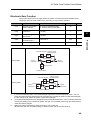
Example: Synchronous Operation
Slave Inverter
Master Inverter
SAP, SBP
SAN, SBN
AP, BP
AN, BN
EG5
EG5
EAP, EBP
EAN, EBN
Functions
4
Main
motor
EAP, EBP
EAN, EBN
Sub
motor
M
EC
M
EC
For the Inverter (master Inverter) on the main motor side, you can select either the speed control or
pulse train position control mode.
For the Inverter (slave Inverter) on the sub motor side, you need to select the pulse train position
control mode.
Configuration Example
• Main motor
: Number of encoder pulses = 1024
• Sub motor
: Number of encoder pulses = 3000
• Main motor rpm : Sub motor rpm = 2:1
For operation under the above conditions, set the following data in the slave Inverter.
Pulse train mode selection (P013)
Electronic gear setting position selection (P019)
Electronic gear ratio numerator (P020)
Electronic gear ratio denominator (P021)
: 00 (pulse with 90° phase difference)
: 01 (REF)
: 3000
: 1024 × 2 = 2048
The following shows an example of the ratio of slave rpm to master rpm depending on the P019 to
P021 settings.
(Note that the same number of encoder pulses (1024 pulses) should be set on both Inverters.)
REF
(Position command side)
REF
(Position command side)
FB
(Position feedback side)
FB
(Position feedback side)
Electronic gear ratio
numerator (P020)
1024
2048
1024
2048
Electronic gear ratio
denominator (P021)
2048
1024
2048
1024
1/2
2
2
1/2
Electronic gear setting
position selection (P019)
Slave rpm/
Master rpm
4-9
4-3 Pulse Train Position Control Mode
Configuration Example
• Main motor
: Number of encoder pulses = 1024
• Sub motor
: Number of encoder pulses = 3000
• Main motor rpm : Sub motor rpm = 2:1
For operation under the above conditions, set the following data in the Inverter on the sub motor
side.
Electronic gear setting position selection (P019)
Electronic gear ratio numerator (P020)
Electronic gear ratio denominator (P021)
: 01 (REF)
: 3000
: 1024 × 2 = 2048
4
FFWG
+
+
G
REF
Functions
Position control
feed forward gain
-
ASR
+
Position loop gain
N
D
FB
Electronic gear setting position = 00 (FB)
FFWG
Position control
feed forward gain
REF
N
D
+
+
G
-
+
ASR
Position loop gain
FB
Electronic gear setting position = 01 (REF)
4-10
4-3 Pulse Train Position Control Mode
Motor Gear Ratio Setting Function
This function is useful for a system with an optional encoder installed on the machine side.
Functions
4
Set the number of actual encoder pulses in encoder pulses P011.
Set a motor-to-encoder rpm ratio in motor gear ratio numerator/denominator P028/P029.
With the above settings, the number of encoder pulses converted into motor shaft data is set in the
Inverter.
This function performs speed/position detection based on the number of encoder pulses converted
into motor shaft data, and calculates the orientation stop position based on the number of encoder
pulses (P011).
Parameter No.
Function name
P028
Motor gear ratio
numerator
P029
Motor gear ratio
denominator
P011
Encoder pulses
Data
0. to 9999
Set a motor-to-encoder rpm ratio.
128. to 9999./1000 to 6553 (10000 to 65535)
Set the number of actual encoder pulses.
Default setting
Unit
1.
−
1024.
Pulse
Note: Make sure that the N/D setting is within the range of 1/50 ≤ N/D ≤ 20.
(N: Motor gear ratio numerator, D: Motor gear ratio denominator)
<Example>
Encoder
(1024 pulses)
Gear/Load
(1:10)
Motor
When the motor-to-encoder rpm ratio is 1:10, set the following data.
• Number of encoder pulses (P011)
• Motor gear ratio numerator (P028)
• Motor gear ratio denominator (P029)
: 1024
: 10
: 100
In this case, the orientation stop position is defined as 4096 divisions of the encoder’s one rotation.
Note that the concept of the stop position is inverted from the description in "Orientation stop position conceptual drawing" (page 4-14).
Position Bias Function
Set this function to apply position command bias in the pulse train position control mode.
The set number of pulses is added to a change value at 2 ms intervals. This is used for adjusting
the phase of synchronization points during synchronous operation.
Set an addition value in position bias amount P024. A positive value adds the value in the forward
direction.
Related functions
4-11
P024
4-3 Pulse Train Position Control Mode
Speed Bias Function
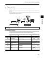
This function applies speed command bias in the pulse train position control mode.
Set a bias value in frequency addition amount A145, and select a sign in frequency addition direction A146.
Allocate 50 (ADD) to any of the multi-function inputs. While the ADD terminal is turned ON, the bias
value is added to the speed command.
Speed bias
4
A145
Position bias
ADD terminal
P024
Functions
Set with A146.
+/-
Position command variation
Position control
Speed control
Speed feedback value
Position feedback variation
Related
functions
A145, A146
Orientation Function
This function determines a motor position at a single desired point during one rotation of the motor,
and can be used to exchange tools for a machine tool main spindle or others.
During positioning, the Z-pulse (one rotation position signal) is used as the reference signal. Input
Z-pulse between EZP and EZN.
Parameter No.
Function name
Data
P011
Encoder pulses
128. to 9999./1000 to 6553
(10000 to 65530)
P014
Orientation stop position
0. to 4095.
P015
Orientation speed setting
0.00 to 99.99/100.0 to 120.0
P016
Orientation direction
setting
00: Forward side
P017
Position ready range
setting
0. to 9999./
1000 (10000)
P018
Position ready delay time
setting
P023
Position loop gain
01: Reverse side
Default setting
Unit
1024.
Pulse
0.
−
5.00
Hz
00
5.
Pulse
0.00 to 9.99
0.00
s
0.00 to 99.99/100.0
0.50
rad/s
4-12
4-3 Pulse Train Position Control Mode
Parameter No.
Data
Default setting
C001 to C008
Multi-function inputs 1 to 8
45: ORT (orientation)
selection
−
C021 to C025
Multi-function output
terminal selection
−
C026
Relay output (MA, MB)
function selection
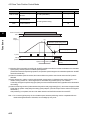
RUN commands (FW/RV)
ORT terminal
Unit
−
23: POK (position ready)
05
ON
ON
Output
frequency
Functions
4
Function name
(2)
(1)
Orientation speed setting (P015)
(3)
Position ready range setting (P017)
Z pulse
POK signal
ON
(Position ready)
Speed control Position control
(4)
Position ready delay time setting
(P018)
(1) When the RUN command is turned ON with the ORT terminal turned ON, the Inverter accelerates to the orientation
speed (P015), and then performs constant speed operation.
(If the RUN command is input during operation, the operation speed changes to the orientation speed when the ORT
terminal is turned ON.)
(2) After the orientation speed is reached, the Inverter shifts to the position control mode when the first Z-pulse is
detected.
(3) During forward run, position control is performed with a target value of “Orientation stop position (P014) + one
rotation”; During reverse run, with a target value of “Orientation stop position (P014) + two rotations”.
In this step, the higher the position loop gain (P023), the shorter the deceleration time (regardless of the deceleration
time setting).
(4) After the remaining number of pulses reaches the position ready range setting (P017), the Inverter outputs the POK
signal after the position ready delay time setting (P018) elapses. (The POK output remains until the ORT signal is
turned OFF.)
After positioning is completed, the servo lock status remains until the RUN command is turned OFF.
Note 1: Do not set a high frequency for the orientation speed, because positioning must be completed within two
rotations during deceleration. Otherwise, an overvoltage trip may occur.
4-13
4-3 Pulse Train Position Control Mode
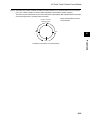
Note 2: Orientation stop position is defined as 4096 (0 to 4095) divisions of one forward rotation from the reference
point. (The number of divisions is fixed to 4096, regardless of the encoder’s number of pulses.)
The reference point is defined as the point where the pulse is input between EZP and EZN. Below is the layout
of the stop target position. (Positive-phase connection)
Motor shaft viewed from motor
shaft load side
Position of Z pulse
Reference point
0
3072
1024
4
Functions
2048
Orientation stop position conceptual drawing
4-14
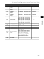
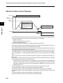
4-4 Absolute Position/High-resolution Absolute Position Control Modes
4-4 Absolute Position/High-resolution
Absolute Position Control Modes
To use the absolute position control mode, set V/f characteristics selection A044 to “05” (V2), and
V2 control mode selection P012 to “02” (APR2: absolute position control).
When “03” (high-resolution absolute position control) is selected in V2 control mode selection P012,
control is based on ×4 the number of pulses used for internal operations.
(Set the multi-step position command and position range specification for ×4 multiplication control.)
4
Functions
The position command can be changed up to 8 steps, depending on combinations of multi-function
inputs.
Zero return speed can be selected from one low speed and two high speeds.
(The orientation function, described in the previous section, is not available.)
By using the teaching function, you can set the position command while running the machine.
By allocating “73” (SPD) to a multi-function input, you can switch between the speed and position
controls.
For data with many digits (e.g. position command), only the higher 4 digits are displayed.
Parameter No.
Function name
Default setting
Unit
P012
V2 control mode selection
02: APR2 (absolute position control mode)
03: HAPR (high-resolution absolute position
control mode)
00
−
P023
Position loop gain
0.00 to 99.99/100.0
0.50
rad/s
P060
Multi-step position
command 0
Position range specification (reverse side)
to Position range specification (forward side)
0
−
P061
Multi-step position
command 1
Position range specification (reverse side)
to Position range specification (forward side)
0
−
P062
Multi-step position
command 2
Position range specification (reverse side)
to Position range specification (forward side)
0
−
P063
Multi-step position
command 3
Position range specification (reverse side)
to Position range specification (forward side)
0
−
P064
Multi-step position
command 4
Position range specification (reverse side)
to Position range specification (forward side)
0
−
P065
Multi-step position
command 5
Position range specification (reverse side)
to Position range specification (forward side)
0
−
P066
Multi-step position
command 6
Position range specification (reverse side)
to Position range specification (forward side)
0
−
P067
Multi-step position
command 7
Position range specification (reverse side)
to Position range specification (forward side)
0
−
P068
Zero return mode
00: Low
01: Hi1
02: Hi2
00
−
P069
Zero return direction
selection
00: Forward side
01: Reverse side
00
−
4-15
Data
4-4 Absolute Position/High-resolution Absolute Position Control Modes
Parameter No.
Function name
Data
Default setting
Unit
P070
Low-speed zero return
frequency
0.00 to 10.00
0.00
Hz
P071
High-speed zero return
frequency
0.00 to 99.99/100.0 to 400.0
0.00
Hz
P072
Position range
specification
(forward)
0 to +268435456 : when APR2 is selected
0 to +1073741823 : when HAPR is selected
268435455
−
P073
Position range
specification
(reverse)
−268435456 to 0 : when APR2 is selected
−1073741823 to 0 : when HAPR is selected
−268435455
−
P074
Teaching selection
00: Multi-step position command 0 (P060)
01: Multi-step position command 1 (P061)
02: Multi-step position command 2 (P062)
03: Multi-step position command 3 (P063)
04: Multi-step position command 4 (P064)
05: Multi-step position command 5 (P065)
06: Multi-step position command 6 (P066)
07: Multi-step position command 7 (P067)
00
−
C169
Multi-step speed/position
determination time
0. to 200. (× 10 ms)
0
ms
d029
Position command monitor −1073741823 to +1073741823
−
−
d030
Current position monitor
−1073741823 to +1073741823
−
−
Multi-function inputs 1 to 8
selection
45: ORT (orientation)
54: SON (servo ON)
66: CP1 (position command selection 1)
67: CP2 (position command selection 2)
68: CP3 (position command selection 3)
69: ORL (zero return limit signal)
70: ORG (zero return startup signal)
71: FOT (forward driving stop)
72: ROT (reverse driving stop)
73: SPD (speed/position switching)
−
−
Reset selection
03: Does not initialize internal data during reset.
0
−
C102
4-16
Functions
C001 to
C008
4
4-4 Absolute Position/High-resolution Absolute Position Control Modes
Absolute Position Control Operation
RUN command
ON
Output
frequency (Hz)
Speed
command
4
Functions
When the position command
level is low, the motor
decelerates and its position is
determined before the output
frequency reaches the speed
command level.
Position ready range setting (P017)
Position
POK signal
ON
Position ready delay time setting
(P018)
In the absolute position control mode, the Inverter moves to the target position according to the following parameter settings, and is then set in the position servo lock status.
• Position command
• Speed command (frequency reference)
• Acceleration/Deceleration time
(The servo lock status is retained until the RUN command is turned OFF.)
The frequency reference and acceleration/deceleration command for absolute position control conform to the parameters selected when the RUN command is ON.
If the position command is set to a low value, the Inverter may start deceleration and perform positioning before the speed command value is reached.
In the absolute position control mode, the direction of RUN command (FW or RV) does not refer to
the rotating direction. The FW or RV signal starts or stops the Inverter. The Inverter runs forward
when (Target position − Current position) is a positive value, or runs in reverse when it is a negative
value.
If you do not perform zero return operation, the position at power-on is regarded as the origin (position = 0).
When position command is set to zero, position ready is set when the RUN command is turned ON.
In reset selection C102, select “03” (trip reset only).
*
If reset selection C102 is not set to “03”, turning ON the Inverter’s reset terminal (or RESET key)
clears the current position counter. To operate the Inverter by using the current position counter
value after resetting a trip by turning on the reset terminal (or RESET key), be sure to set reset
selection C102 to “03”.
If PCLR is allocated, turning on the PCLR terminal clears the current position counter.
(The internal position deviation counter will be simultaneously cleared.)
The absolute position control mode disables the ATR terminal. (Torque control is disabled.)
The absolute position control mode disables the STAT terminal. (Pulse train position control is disabled.)
The absolute position control mode disables the orientation function.
(However, the ORT terminal is used for teaching, as described later.)
4-17
4-4 Absolute Position/High-resolution Absolute Position Control Modes
Multi-step Position Switching Function (CP1/CP2/CP3)
By allocating “66” to “68” (CP1 to CP3) to any of multi-function inputs 1 to 8 (C001 to C008), you
can select from multi-step positions 0 to 7.
Set position commands in multi-step position commands 0 to 7 (P060 to P067).
If no position command is allocated to the terminals, multi-step position command 0 (P060) is defined as the position command.
CP3
CP2
CP1
Multi-step position 0
0
0
0
Multi-step position 1
0
0
1
Multi-step position 2
0
1
0
Multi-step position 3
0
1
1
Multi-step position 4
1
0
0
Multi-step position 5
1
0
1
Multi-step position 6
1
1
0
Multi-step position 7
1
1
1
4
Functions
Position command
When you input a multi-step position command, you can set the wait time until the terminal input is
determined. This prevents the transition status from being applied before it is determined.
You can adjust the determination time in multi-step speed/position determination time C169. If no
input is made during the time set in C169, the data is determined after the set time elapses. (Note
that the longer the determination time, the slower the input response.)
Without determination
time (C169)
With determination time (C169)
7
3
Position command
5 4
1
CP1
CP2
CP3
Determination time (C169)
4-18
4-4 Absolute Position/High-resolution Absolute Position Control Modes
Speed/Position Switching Function (SPD)
This function is used for speed control operation.
Allocate “73” (SPD) to any of the multi-function inputs.
While the SPD terminal is turned ON, the current position counter is retained at zero. The Inverter
shifts to the position control mode when the SPD terminal is turned OFF during operation. (Speed/
Position switching)
With the position command set to 0, the Inverter shifts to the stop operation when the SPD terminal
is turned OFF
(Hunting may occur, depending on the position loop gain setting.)
4
Functions
While the SPD terminal is turned ON, the Inverter runs in the direction specified by the RUN command. To shift from speed control to position control, be careful about the polarity sign of the RUN
command.
Output frequency
Position count started
Speed control
Position control
Time
Target position
SPD terminal
4-19
ON
4-4 Absolute Position/High-resolution Absolute Position Control Modes
Zero Return Function
This function performs three types of zero return operations according to the zero return mode
P068. When zero return is complete, the current position is cleared to zero.
You can select the zero return direction in zero return direction selection P069.
If zero return is not performed, the Inverter performs position control with the position at power-on
defined as the origin.
<Low-speed zero return (P068 = 00)>
ON
ORG terminal
ON
ORL terminal
Output
frequency
(2)
(1)
Position
Origin
<High-speed zero return 1 (P068 = 01)>
ON
ORG terminal
ON
ORL terminal
(2)
Output
frequency
High-speed zero
return frequency
(P071)
(3)
(1)
Origin
(5)
Position
(4)
Low-speed zero
return frequency
(P070)
<High-speed zero return 2 (P068 = 02)>
ON
ORG terminal
ON
ORL terminal
(2)
Output
frequency
(1)
(6)
(5)
Z pulse
High-speed zero
return frequency (P071)
Low-speed
(3)
zero return
frequency (P070)
(7)
Origin Position
(4)
Low-speed zero
return frequency (P070)
4
Functions
Low-speed zero
return frequency
(3) (P070)
(1) The Inverter accelerates to the low-speed zero
return frequency according to the acceleration
time setting.
(2) The Inverter runs at the low-speed zero return
frequency.
(3) The Inverter performs positioning when the ORL
signal is input.
(1) The Inverter accelerates to the high-speed zero
return frequency according to the acceleration
time setting.
(2) The Inverter runs at the high-speed zero return
frequency.
(3) The Inverter starts deceleration when the ORL
signal is turned ON.
(4) The Inverter runs in reverse at the low-speed
zero return frequency.
(5) The Inverter performs positioning when the ORL
signal is turned OFF.
(1) The Inverter accelerates to the high-speed zero
return frequency according to the acceleration
time setting.
(2) The Inverter runs at the high-speed zero return
frequency.
(3) The Inverter starts deceleration when the ORL
signal is turned ON.
(4) The Inverter runs in reverse at the low-speed
zero return frequency.
(5) The Inverter starts deceleration when the ORL
signal is turned OFF.
(6) The Inverter runs forward at the low-speed zero
return frequency.
(7) The Inverter performs positioning at the first Zpulse position after the ORL signal is turned ON.
4-20
4-4 Absolute Position/High-resolution Absolute Position Control Modes
Forward/Reverse Run Stop Function (FOT/ROT)
With a signal from the control range limit switch, this function prevents the Inverter from running outside the specified operation range.
The torque limit is set to 10% on the forward side when the FOT terminal is turned on, and on the
reverse side when the ROT terminal is turned on.
This function can be used as the limit switch at the machine end, when “71” (FOT) and “72” (ROT)
are allocated to any of multi-function inputs 1 to 8 (C001 to C008).
Functions
4
Position Range Specification Function
Set a forward/reverse position control range in position range specification (forward) P072 and position range specification (reverse) P073. If the current position counter exceeds this setting range,
the position control range trip (E63.* or E73.*) occurs, and the Inverter goes into free-run status.
The upper limit setting of multi-step position commands 0 to 7 is limited by this position range setting.
(You cannot set a position command beyond the position range.)
Teaching Function
This function starts or stops the motor at a desired position and stores the current position in a desired position command area.
Allocate “45” (ORT) to any of multi-function inputs 1 to 8 (C001 to C008).
When V2 control mode selection P012 is set to “02” (absolute position control) or “03” (high-resolution absolute position control), the relevant terminal serves as a teaching terminal.
Related functions
C001 to C008, C012, C074
<Teaching Procedure>
(1) In teaching selection P074, select the position command you want to set.
(2) Move the workpiece.
• Input the RUN command with the ORT terminal turned ON. At this time, the speed command
and acceleration/deceleration time conform to the currently selected parameters.
ORT terminal
ON
RUN command
ON
Output frequency
Depends on the speed command selected.
Position
* If the Inverter control circuit (Ro, To) is turned on, teaching is enabled.
The current position counter operates even if the workpiece is moved by an external device.
Teaching is therefore enabled even while the Inverter is stopped.
Note:
4-21
Make sure that the Inverter power circuit (R/L1, S/L2, T/L3) is turned off. Also, make sure
that the Inverter’s output (U/T1, V/T2, W/T3) is disconnected from the motor. Not doing so
may result in injury and/or damage to the equipment.
4-4 Absolute Position/High-resolution Absolute Position Control Modes
(3) When the target position is reached, press the Enter key on the Digital Operator. Press the key
on the data display screen (the PRG LED indicator is lit).
(4) The current position is set to the area corresponding to the position command source set in
teaching selection P074.
(However, the P074 setting is not stored. After the power is shut off or after reset, this parameter
is indicated as “00” (x00).)
Position commands to be set
00
P060: Multi-step position command 0
01
P061: Multi-step position command 1
02
P062: Multi-step position command 2
03
P063: Multi-step position command 3
04
P064: Multi-step position command 4
05
P065: Multi-step position command 5
06
P066: Multi-step position command 6
07
P067: Multi-step position command 7
4
Servo ON Function
This function brings the Inverter into speed servo lock status via an input terminal when “05” (sensor
vector control) is selected in V/f characteristics selection A044.
Allocate 54 (SON) to the desired multi-function input.
The Inverter will not accept the RUN command unless the SON terminal is turned on when SON is
allocated.
If the SON terminal is turned off during operation, the Inverter goes into free-run status. When the
SON terminal is turned on again, the Inverter restarts according to the setting of free-run stop selection b088.
This function cannot be simultaneously used with the preliminary excitation function (55: FOC). If
FOC and SON are both allocated to multi-function inputs, priority is given to FOC, and SON is disabled.
SON
ON
FW(RV)
ON
ON
ON
ON
Does not operate
because the SON
terminal is OFF.
Output
frequency
Free running
Restarts according to b088.
Speed servo-lock status
Related functions
A044, C001 to C008
4-22
Functions
P074 set values
4-4 Absolute Position/High-resolution Absolute Position Control Modes
Pulse Train Frequency Input
This function allows you to use a pulse train input to the SAP-SAN terminals on the PG Board as
frequency reference or PID feedback value in each control mode.
(This function can be used in all control modes.)
Set the input frequency at the maximum frequency in pulse train frequency scale P055.
The analog input start/end function cannot be used. To limit the input frequency, use pulse train frequency bias amount P057 and pulse train frequency limit P058.
4
Default
setting
Unit
1.0 to 50.0: Set the input frequency at the
maximum frequency.
25.0
kHz
Pulse train frequency filter
time constant
0.01 to 2.00: Set a filter time constant for
pulse train input.
0.10
s
P057
Pulse train frequency bias
amount
−100. to +100.
0.
%
P058
Pulse train frequency limit
0. to 100.
100.
%
A001
Frequency reference
selection
06: Pulse train frequency
02
A076
PID feedback selection
03: Pulse train frequency
00
A141
Operation frequency input
A setting
07: Pulse train frequency
02
A142
Operation frequency input
B setting
07: Pulse train frequency
03
Function name
P055
Pulse train frequency scale
P056
Functions
Parameter No.
Data
Pulse train frequency processing block
Bias/Limit
Limit
Frequency
measurement
Hz
%
%
1
1+sT
Hz
Frequency
reference
Bias
Frequency scale (P055)
(1.0 to 50.0 kHz)
First-order lag filter (P056)
Maximum
frequency
(A004)
Note: Set the SWENC switch on the PG Board to “OFF: encoder disconnection detection
disabled”.
4-23
−
Chapter 5
Maintenance Operations
5-1 Operation Selection During Option Error ...... 5-1
5-2 Cause and Countermeasure of Option Errors... 5-2
5-3 Warning Display ............................................... 5-3
5-1 Operation Selection During Option Error
5Maintenance Operations
5-1
Operation Selection During Option Error
You can select whether to trip the Inverter or continue operation ignoring an error when the optional
PG Board causes an error.
Parameter No.
Function name
Data
Default
setting
Changes during operation
Unit
P001
Operation selection at option
1 error
00: Trip
01: Continues operation
00
×
−
P002
Operation selection at option
2 error
00: Trip
01: Continues operation
00
×
−
Note:Even if 01 has been selected in operation selection at option error, the Inverter trips when an
encoder disconnection error (E60, E70) or 3G3AX-PG connection error (E69, E79) occurs.
Refer to "2-6 Switch Settings"(page 2-8).
Maintenance Operations
5
5-1
5-2 Cause and Countermeasure of Option Errors
5-2 Cause and Countermeasure of
Option Errors
The Inverter stops and displays an error in the following cases.
Fault
display
Function
name
Detects encoder disconnection and
connection failure.
ek6k0.
ek7k0.
ek6k2.
ek7k2.
*1
*1
*1
ek6k3.
ek7k3.
*1
ek6k9.
ek7k9.
*1
*2
*3
*1
Encoder
disconnection
Remedy
Check the connection and conductive wire of encoder line.
Detects if the encoder has broken or
the encoder is not the one that spec- Use the specified encoder instead.
ifies the line driver output.
Detects if an encoder without phase
Z has been used
Turn OFF the SWENC-2 on the
PG Board.
Overspeed
Detects if the motor rotation has exceeded (Maximum frequency*2)×(Overspeed error detection
level [P026]).*3
Adjust the parameters of Kp and J
relating to the speed control and
reduce overshooting.
Positioning
error
Set the larger value for position
Detects if the current position devialoop gain of position control.
tion against the position command
Reduce the pulse per unit time of
value exceeds 1,000,000 pulses
the pulse train position command
during position control.
input.
Position control range trip
Shuts off the output and displays an
error when the current position exceeds the set values for the positionCorrect the position command.
ing range specifications for both
Forward (P072) and Reverse (P073)
during absolute position control.
3G3AX-PG
connection
error
Detects PG Board connection
failure.
Check the PG Board connection.
Appears when the PG Board is connected to Board port 2.
Upper limit value is applied when the frequency upper limit (A061) is set.
This error could occur again even if the trip is reset during free running. Reset the trip after
stopping motor operation.
5-2
5
Maintenance Operations
ek6k1.
ek7k1.
Description
5-3 Warning Display
5-3 Warning Display
For warnings other than the one mentioned below, refer to the general-purpose Inverter 3G3RX
User’s Manual.
Fault display
Description
Displays when the orientation speed setting (P015) becomes larger than
the maximum frequency (A004).
Check the orientation speed setting and the maximum frequency.
Maintenance Operations
5
5-3
Chapter 6
Specifications
6-1 Product Specifications .................................... 6-1
6-1 Product Specifications
6Specifications
6-1 Product Specifications
Item
Speed control
Specifications
Encoder feedback
Speed control system
Position command
Position control
Electronic gear
6
Stop position
Specifications
Orientation
Protective functions
*1
6-1
Speed
• Standard number of encoder pulses: 1024 pulses/r
• Maximum input number of pulses: 100k pulses/s
• Proportional integral (PI)/ Proportional (P) control
• The pulse train can be input in three modes.
Mode 0: Pulse train with 90° phase difference
Mode 1: Forward/Reverse command + Pulse train
Mode 2: Forward pulse train + Reverse pulse train
The input mode depends on the Inverter setting.
• Maximum input number of pulses: 100k pulses/s
• Pulse ratio A/B (A, B: 1 to 9999 can be set)
• Available setting range: 1/50 ≤ A/B ≤ 20
• 4096 divisions per one motor rotation*1
• Orientation speed and rotation direction settings
available
• Encoder cable disconnection protection
• Overspeed protection (Overspeed error detection level
(P026))
• Positioning error
• 3G3AX-PG connection error
The Inverter setting or external input is available. Note that the 3G3AX-DI Board is required
separately for the external input.
Terms and Conditions of Sale
1. Offer; Acceptance. These terms and conditions (these "Terms") are deemed
part of all quotes, agreements, purchase orders, acknowledgments, price lists,
catalogs, manuals, brochures and other documents, whether electronic or in
writing, relating to the sale of products or services (collectively, the "Products")
by Omron Electronics LLC and its subsidiary companies (“Omron”). Omron
objects to any terms or conditions proposed in Buyer’s purchase order or other
documents which are inconsistent with, or in addition to, these Terms.
2. Prices; Payment Terms. All prices stated are current, subject to change without notice by Omron. Omron reserves the right to increase or decrease prices
on any unshipped portions of outstanding orders. Payments for Products are
due net 30 days unless otherwise stated in the invoice.
3. Discounts. Cash discounts, if any, will apply only on the net amount of invoices
sent to Buyer after deducting transportation charges, taxes and duties, and will
be allowed only if (i) the invoice is paid according to Omron’s payment terms
and (ii) Buyer has no past due amounts.
4. Interest. Omron, at its option, may charge Buyer 1-1/2% interest per month or
the maximum legal rate, whichever is less, on any balance not paid within the
stated terms.
5. Orders. Omron will accept no order less than $200 net billing.
6. Governmental Approvals. Buyer shall be responsible for, and shall bear all
costs involved in, obtaining any government approvals required for the importation or sale of the Products.
7. Taxes. All taxes, duties and other governmental charges (other than general
real property and income taxes), including any interest or penalties thereon,
imposed directly or indirectly on Omron or required to be collected directly or
indirectly by Omron for the manufacture, production, sale, delivery, importation, consumption or use of the Products sold hereunder (including customs
duties and sales, excise, use, turnover and license taxes) shall be charged to
and remitted by Buyer to Omron.
8. Financial. If the financial position of Buyer at any time becomes unsatisfactory
to Omron, Omron reserves the right to stop shipments or require satisfactory
security or payment in advance. If Buyer fails to make payment or otherwise
comply with these Terms or any related agreement, Omron may (without liability and in addition to other remedies) cancel any unshipped portion of Products sold hereunder and stop any Products in transit until Buyer pays all
amounts, including amounts payable hereunder, whether or not then due,
which are owing to it by Buyer. Buyer shall in any event remain liable for all
unpaid accounts.
9. Cancellation; Etc. Orders are not subject to rescheduling or cancellation
unless Buyer indemnifies Omron against all related costs or expenses.
10. Force Majeure. Omron shall not be liable for any delay or failure in delivery
resulting from causes beyond its control, including earthquakes, fires, floods,
strikes or other labor disputes, shortage of labor or materials, accidents to
machinery, acts of sabotage, riots, delay in or lack of transportation or the
requirements of any government authority.
11. Shipping; Delivery. Unless otherwise expressly agreed in writing by Omron:
a. Shipments shall be by a carrier selected by Omron; Omron will not drop ship
except in “break down” situations.
b. Such carrier shall act as the agent of Buyer and delivery to such carrier shall
constitute delivery to Buyer;
c. All sales and shipments of Products shall be FOB shipping point (unless otherwise stated in writing by Omron), at which point title and risk of loss shall
pass from Omron to Buyer; provided that Omron shall retain a security interest in the Products until the full purchase price is paid;
d. Delivery and shipping dates are estimates only; and
e. Omron will package Products as it deems proper for protection against normal handling and extra charges apply to special conditions.
12. Claims. Any claim by Buyer against Omron for shortage or damage to the
Products occurring before delivery to the carrier must be presented in writing
to Omron within 30 days of receipt of shipment and include the original transportation bill signed by the carrier noting that the carrier received the Products
from Omron in the condition claimed.
13. Warranties. (a) Exclusive Warranty. Omron’s exclusive warranty is that the
Products will be free from defects in materials and workmanship for a period of
twelve months from the date of sale by Omron (or such other period expressed
in writing by Omron). Omron disclaims all other warranties, express or implied.
(b) Limitations. OMRON MAKES NO WARRANTY OR REPRESENTATION,
EXPRESS OR IMPLIED, ABOUT NON-INFRINGEMENT, MERCHANTABIL-
14.
15.
16.
17.
18.
ITY OR FITNESS FOR A PARTICULAR PURPOSE OF THE PRODUCTS.
BUYER ACKNOWLEDGES THAT IT ALONE HAS DETERMINED THAT THE
PRODUCTS WILL SUITABLY MEET THE REQUIREMENTS OF THEIR
INTENDED USE. Omron further disclaims all warranties and responsibility of
any type for claims or expenses based on infringement by the Products or otherwise of any intellectual property right. (c) Buyer Remedy. Omron’s sole obligation hereunder shall be, at Omron’s election, to (i) replace (in the form
originally shipped with Buyer responsible for labor charges for removal or
replacement thereof) the non-complying Product, (ii) repair the non-complying
Product, or (iii) repay or credit Buyer an amount equal to the purchase price of
the non-complying Product; provided that in no event shall Omron be responsible for warranty, repair, indemnity or any other claims or expenses regarding
the Products unless Omron’s analysis confirms that the Products were properly handled, stored, installed and maintained and not subject to contamination, abuse, misuse or inappropriate modification. Return of any Products by
Buyer must be approved in writing by Omron before shipment. Omron Companies shall not be liable for the suitability or unsuitability or the results from the
use of Products in combination with any electrical or electronic components,
circuits, system assemblies or any other materials or substances or environments. Any advice, recommendations or information given orally or in writing,
are not to be construed as an amendment or addition to the above warranty.
See http://www.omron247.com or contact your Omron representative for published information.
Limitation on Liability; Etc. OMRON COMPANIES SHALL NOT BE LIABLE
FOR SPECIAL, INDIRECT, INCIDENTAL, OR CONSEQUENTIAL DAMAGES,
LOSS OF PROFITS OR PRODUCTION OR COMMERCIAL LOSS IN ANY
WAY CONNECTED WITH THE PRODUCTS, WHETHER SUCH CLAIM IS
BASED IN CONTRACT, WARRANTY, NEGLIGENCE OR STRICT LIABILITY.
Further, in no event shall liability of Omron Companies exceed the individual
price of the Product on which liability is asserted.
Indemnities. Buyer shall indemnify and hold harmless Omron Companies and
their employees from and against all liabilities, losses, claims, costs and
expenses (including attorney's fees and expenses) related to any claim, investigation, litigation or proceeding (whether or not Omron is a party) which arises
or is alleged to arise from Buyer's acts or omissions under these Terms or in
any way with respect to the Products. Without limiting the foregoing, Buyer (at
its own expense) shall indemnify and hold harmless Omron and defend or settle any action brought against such Companies to the extent based on a claim
that any Product made to Buyer specifications infringed intellectual property
rights of another party.
Property; Confidentiality. Any intellectual property in the Products is the exclusive property of Omron Companies and Buyer shall not attempt to duplicate it
in any way without the written permission of Omron. Notwithstanding any
charges to Buyer for engineering or tooling, all engineering and tooling shall
remain the exclusive property of Omron. All information and materials supplied
by Omron to Buyer relating to the Products are confidential and proprietary,
and Buyer shall limit distribution thereof to its trusted employees and strictly
prevent disclosure to any third party.
Export Controls. Buyer shall comply with all applicable laws, regulations and
licenses regarding (i) export of products or information; (iii) sale of products to
“forbidden” or other proscribed persons; and (ii) disclosure to non-citizens of
regulated technology or information.
Miscellaneous. (a) Waiver. No failure or delay by Omron in exercising any right
and no course of dealing between Buyer and Omron shall operate as a waiver
of rights by Omron. (b) Assignment. Buyer may not assign its rights hereunder
without Omron's written consent. (c) Law. These Terms are governed by the
law of the jurisdiction of the home office of the Omron company from which
Buyer is purchasing the Products (without regard to conflict of law principles). (d) Amendment. These Terms constitute the entire agreement between
Buyer and Omron relating to the Products, and no provision may be changed
or waived unless in writing signed by the parties. (e) Severability. If any provision hereof is rendered ineffective or invalid, such provision shall not invalidate
any other provision. (f) Setoff. Buyer shall have no right to set off any amounts
against the amount owing in respect of this invoice. (g) Definitions. As used
herein, “including” means “including without limitation”; and “Omron Companies” (or similar words) mean Omron Corporation and any direct or indirect
subsidiary or affiliate thereof.
Certain Precautions on Specifications and Use
1. Suitability of Use. Omron Companies shall not be responsible for conformity
with any standards, codes or regulations which apply to the combination of the
Product in the Buyer’s application or use of the Product. At Buyer’s request,
Omron will provide applicable third party certification documents identifying
ratings and limitations of use which apply to the Product. This information by
itself is not sufficient for a complete determination of the suitability of the Product in combination with the end product, machine, system, or other application
or use. Buyer shall be solely responsible for determining appropriateness of
the particular Product with respect to Buyer’s application, product or system.
Buyer shall take application responsibility in all cases but the following is a
non-exhaustive list of applications for which particular attention must be given:
(i) Outdoor use, uses involving potential chemical contamination or electrical
interference, or conditions or uses not described in this document.
(ii) Use in consumer products or any use in significant quantities.
(iii) Energy control systems, combustion systems, railroad systems, aviation
systems, medical equipment, amusement machines, vehicles, safety equipment, and installations subject to separate industry or government regulations.
(iv) Systems, machines and equipment that could present a risk to life or property. Please know and observe all prohibitions of use applicable to this Product.
NEVER USE THE PRODUCT FOR AN APPLICATION INVOLVING SERIOUS
RISK TO LIFE OR PROPERTY OR IN LARGE QUANTITIES WITHOUT
ENSURING THAT THE SYSTEM AS A WHOLE HAS BEEN DESIGNED TO
2.
3.
4.
5.
ADDRESS THE RISKS, AND THAT THE OMRON’S PRODUCT IS PROPERLY RATED AND INSTALLED FOR THE INTENDED USE WITHIN THE
OVERALL EQUIPMENT OR SYSTEM.
Programmable Products. Omron Companies shall not be responsible for the
user’s programming of a programmable Product, or any consequence thereof.
Performance Data. Data presented in Omron Company websites, catalogs
and other materials is provided as a guide for the user in determining suitability and does not constitute a warranty. It may represent the result of Omron’s
test conditions, and the user must correlate it to actual application requirements. Actual performance is subject to the Omron’s Warranty and Limitations
of Liability.
Change in Specifications. Product specifications and accessories may be
changed at any time based on improvements and other reasons. It is our practice to change part numbers when published ratings or features are changed,
or when significant construction changes are made. However, some specifications of the Product may be changed without any notice. When in doubt, special part numbers may be assigned to fix or establish key specifications for
your application. Please consult with your Omron’s representative at any time
to confirm actual specifications of purchased Product.
Errors and Omissions. Information presented by Omron Companies has been
checked and is believed to be accurate; however, no responsibility is assumed
for clerical, typographical or proofreading errors or omissions.
OMRON ELECTRONICS LLC • THE AMERICAS HEADQUARTERS
Schaumburg, IL USA • 847.843.7900 • 800.556.6766 • www.omron247.com
OMRON CANADA, INC. • HEAD OFFICE
OMRON ARGENTINA • SALES OFFICE
Toronto, ON, Canada • 416.286.6465 • 866.986.6766 • www.omron.ca
Cono Sur • 54.11.4787.1129
OMRON ELETRÔNICA DO BRASIL LTDA • HEAD OFFICE
OMRON CHILE • SALES OFFICE
São Paulo, SP, Brasil • 55.11.2101.6300 • www.omron.com.br
Santiago 56.2206.4592
OMRON ELECTRONICS MEXICO SA DE CV • HEAD OFFICE
OTHER OMRON LATIN AMERICA SALES
Apodaca, N.L. • 52.811.156.99.10 • [email protected]
56.2206.4592
I564-E1-01
Note: Specifications are subject to change.
© 2008 Omron Electronics LLC
Printed in U.S.A.