1
Installation, Operation and Service Guide
Contents
1. The JustiFire System ......................................................................................................................................................................4
1.1 Introduction................................................................................................................................................................................4
1.2 Overview................................................................................................................................................................................... 4
1.2.1 The Audio Inputs ..............................................................................................................................................................6
1.2.2 The Fire Panel Interface ..................................................................................................................................................7
1.2.3 The Digital Signal Processor(DSP) and Digital Message Stores....................................................................................7
1.2.4 The Power Amplifiers.......................................................................................................................................................8
1.2.5 The Audio Output Zones and the Loudspeaker Circuit Fault Detector ...........................................................................9
1.2.6 The Fault Reporting System .............................................................................................................................................9
1.2.7 The Battery Charger.......................................................................................................................................................10
1.2.8 The Power Supply...........................................................................................................................................................10
1.2.9 The Cabinet ....................................................................................................................................................................10
2. Unpacking......................................................................................................................................................................................11
3. Mechanical Installation ................................................................................................................................................................12
4. Electrical Installation ...................................................................................................................................................................13
4.1 Connection of Mains power.....................................................................................................................................................13
4.2 Connection of Peripherals........................................................................................................................................................13
4.2.1 Connecting to the Audio Outputs ................................................................................................................................... 13
4.2.2 Connecting to the Audio Output Zone Select Inputs ......................................................................................................14
4.2.3 Connecting to the Fire Panel Inputs ..............................................................................................................................14
4.2.4 Connecting to the Audio Inputs ......................................................................................................................................16
4.2.5 Connecting to the Emergency Relay...............................................................................................................................17
4.2.6 Connecting to the Fault Output Relay............................................................................................................................17
4.3 Connection of the Lead Acid Batteries....................................................................................................................................18
5. Powering Up the JustiFire for the first time ..............................................................................................................................19
6. Configuration using the MIMIC software ..................................................................................................................................20
6.1 General.....................................................................................................................................................................................20
6.2 Set-up .......................................................................................................................................................................................20
6.3 Operation.................................................................................................................................................................................. 20
6.4 The Main Screen ......................................................................................................................................................................20
6.5 The Menu Options ...................................................................................................................................................................21
6.5.1 "Connection Settings"..................................................................................................................................................... 21
6.5.2 "Allow Setup"..................................................................................................................................................................21
6.5.3 "Change Password" .......................................................................................................................................................21
6.5.4 "About JustiFire Mimic" ................................................................................................................................................22
6.5.5 "JustiFire Information" ..................................................................................................................................................22
6.5.6 "JustiFire IO" .................................................................................................................................................................22
6.5.7 "Fault Control"............................................................................................................................................................... 22
6.6 Changing the JustiFire Parameters........................................................................................................................................... 23
6.6.1 Changing the PTT 1 Options..........................................................................................................................................23
6.6.2 Changing the PTT 2-4 Options ......................................................................................................................................23
6.6.3 Changing the Message Input 1-4 Options......................................................................................................................24
6.6.4 Changing the Audio Input 1-4 Options ..........................................................................................................................25
6.6.5 Changing the Voice Storage Options .............................................................................................................................25
6.6.6 Changing the Input Controller Options .........................................................................................................................27
6.6.7 Changing the Audio Controller Options ........................................................................................................................27
6.6.8 Changing the Amplifier Options.....................................................................................................................................28
6.6.9 Changing the Emergency Options..................................................................................................................................28
7. Operation.......................................................................................................................................................................................29
7.1 The Status Indicators................................................................................................................................................................ 29
7.1.1 System Fault ..................................................................................................................................................................29
7.1.2 Display Fault..................................................................................................................................................................29
JustiFire Installation, Operation and Service Guide
2
7.1.3 Power On........................................................................................................................................................................29
7.1.4 Fallback..........................................................................................................................................................................29
7.2 Normal Operation ....................................................................................................................................................................29
7.3 On Receipt of a Fault ...............................................................................................................................................................30
7.4 Password Protected Mode........................................................................................................................................................30
7.5 Accepting a fault or "What to do when the fault buzzer sounds".............................................................................................31
7.6 Clearing a fault or "What to do when a fault has been fixed"..................................................................................................31
7.7 Viewing The Event Log...........................................................................................................................................................32
7.8 Setting the Date and Time........................................................................................................................................................ 32
7.9 Changing the Timeout for the resetting of Accepted Faults ....................................................................................................32
7.10 Changing the User Password .................................................................................................................................................33
7.11 Viewing the DSP Links Information .....................................................................................................................................34
7.12 Viewing the number of DSP resets........................................................................................................................................35
7.13 Exiting the Protected Mode Menu .........................................................................................................................................35
7.14 Keypress Timeout ..................................................................................................................................................................35
8. Servicing & Maintenance.............................................................................................................................................................36
8.1 Daily Checks............................................................................................................................................................................36
8.2 Weekly Checks ........................................................................................................................................................................36
8.3 Quarterly Checks .....................................................................................................................................................................36
8.4 Five Yearly Maintenance.........................................................................................................................................................36
9. Troubleshooting ............................................................................................................................................................................37
9.1 No Audio Output from the System ..........................................................................................................................................37
9.1.1 No Microphone Audio ....................................................................................................................................................37
9.1.2 No Message Audio..........................................................................................................................................................37
9.2 Alarm Messages.......................................................................................................................................................................38
9.2.1 Circuit Fault Monitoring Alarms, Open CCT's, Short CCT's & Earth Faults...............................................................38
9.2.2 System Fault Monitoring Alarms ...................................................................................................................................38
10. Specification ................................................................................................................................................................................39
11. Appendix A: Message definitions ..............................................................................................................................................40
JustiFire Installation, Operation and Service Guide
3
1. The JustiFire System
1.1 Introduction
JustiFire provides a single channel, six zone voice evacuation system. It has been designed as the integral
part of a BS5839 Part 8 (and BS EN 60849) compliant system suited to use in small to medium size offices,
industrial facilities or similar establishments. Compact, wall mounted and self-contained with a 24 hour
battery back up, JustiFire utilises a Windows-based configuration program to provide ease of use in setting
up the system to meet individual requirements.
Flexibility is designed into the equipment allowing larger installations to be catered for.
The main features are:
•
Proven software package
•
Designed for BS5839 Part 8 and EN 60849 compliance
•
Six zone, for paging / music distribution / evacuation
•
Single channel
•
4 Message store (40s per message)
•
Four analogue inputs for 0dB or 100V line
•
Modular design
•
85% efficient 250W class-D amplifiers
•
Silent DC monitoring of loudspeaker circuits
•
CE compliance
1.2 Overview
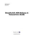
The following chapter provides an overview of the JustiFire system breaking it down into the main elements
which are described and specified in general terms only. It is necessary to consult the remaining chapters
to enable installation and configuration. With reference to the block diagram in figure 1 the JustiFire system
can be divided into the following sections:
1.2.1 The Audio Inputs.
1.2.2 The Fire Panel Interface.
1.2.3 The Digital Signal Processor (DSP) and Digital Message Stores.
1.2.4 The Power Amplifiers.
1.2.5 The Audio Output Zones and the Loudspeaker Circuit Fault Detector.
1.2.6 The Fault Reporting System.
1.2.7 The Battery Charger.
1.2.8 The Power Supply
1.2.9 The Cabinet
JustiFire Installation, Operation and Service Guide
4
DC Line Monitoring
Amplifier A
Audio Input 1
PTT1
Loudspeaker Access Control
Circuit A
Zone 1
Audio
Sleep 1
Sleep
/SC
Audio Input 2
24V
Detector
/Fault
Loudspeaker Zone 1
User Interface
PTT2
Amplifier A fault
Audio Input 3
30Hz critical path monitoring A
Circuit A
PTT3
Zone 2
DC Line Monitoring
Audio Input 4
24V
Loudspeaker Access Control
PTT4
Alarm 1
Alarm 2
Digital
Signal
Processor
Amplifier B
DC Line Monitoring
Circuit A
Audio
Sleep 2
Zone 3
Sleep
/SC
Alarm 4
24V
Circuit B
Detector
/Fault
Alarm 3
Circuit B
Loudspeaker Zone 2
User Interface
30Hz critical path monitoring B
I/O Interface
Circuit B
Loudspeaker Zone 3
User Interface
Amplifier B fault
Common
Delatch
Circuit A
Zone 4
24V
24V
Common Fault Relay
Circuit B
Loudspeaker Zone 4
User Interface
NPN
Circuit A
Zone 5
24V
24V
Circuit B
Loudspeaker Zone 5
User Interface
Emergency Relay
LCD Display and
Fault Capture
Circuit A
Zone 6
24V
Circuit B
Fault Sounder
230VAC Power Supply
Live, Neutral, Earth
Figure 1. JustiFire Block Diagram
Battery Charger
2 x Batteries
Loudspeaker Zone 6
User Interface
JustiFire Installation Operation and Service Guide
5
1.2.1 The Audio Inputs (Input pre-amplifier/router)
This provides an interface with external signal sources. A variety of different inputs are catered for,
including microphone, music source and 100V line systems. When interfacing with 3rd party equipment the
required methods of fault monitoring will vary, so the equipment has the flexibility to cope with all of the
most common variations:
Audio Input Specifications
•
The input interface has four line level galvanically isolated inputs.
•
An option is provided to fit attenuation for connection to 100V line systems.
•
Each audio input can expect a nominal 0dBu input with a maximum headroom of 12dB, any required
limiting or compression will be done at source.
•
Each audio input has an input access control: Press To Talk (PTT). These can be configured via a PC
Mimic program to be normally open or normally closed. The user will be required to provide a volt-free
contact for this operation.
•
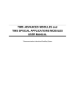
Each audio input has one or two associated outputs, to indicate the availability of that input (a “System
Busy” signal and a “Talk Now” signal) as shown in the table of figure 2.
PTT switch
Busy 1
Busy 2
Busy 3
Busy 4
Talk Now 1
Talk Now 2
Talk Now 3
Talk Now 4
PTT1
PTT2
PTT3
PTT4
N/A
N/A
N/A
N/A
ON
OFF
OFF
OFF
ON
ON
OFF
OFF
ON
ON
ON
OFF
ON
OFF
OFF
OFF
OFF
ON
OFF
OFF
OFF
OFF
ON
OFF
OFF
OFF
OFF
ON
Figure 2. The System Busy and Talk Now Signals
•
Audio input 1 is the default fireman’s microphone and has the highest priority (non-configurable), hence
there is no requirement for a Busy 1 output.
•
Audio inputs 2 – 4 have configurable priority and hence require a Busy output.
•
Each audio input has a configurable chime (Bing Bong etc.) and configurable fault monitoring options,
which are selectable via the PC Mimic program. A link is provided on the DSP card (JP1, 2 and 3 for
audio inputs 2, 3 and 4) to allow the installer to disable fault monitoring for any input with the exception
of input 1, which will always be monitored.
•
PC Mimic selection of fault monitoring modes:
30Hz.
20kHz. (18kHz – 22kHz).
Wide Band (30Hz – 22kHz).
•
Using the PC Mimic program a cascade priority can be set-up. The equipment is shipped with a factory
default priority structure. This is loaded on power up if link JP8 on the DSP card is fitted. Further
information on this is provided in the section on the DSP card.
JustiFire Installation, Operation and Service Guide
6
1.2.2 The Fire Panel Interface
Five Fire Panel Interface connections are provided. These are designated as shown in the table of figure 3.
Figure 3. Fire Panel Input Designations
JustiFire Terminations
PCB Identification
Function
Alarm 1
Alarm 2
Alarm 3
Alarm 4
Delatch
Message store latch 1*
Message store latch 2
Message store latch 3
Message store latch 4
Common de-latch
*See Appendix A for message definitions
•
Each input is provided with a choice of two connection types: These are by Voltage Reversal or by Dry
Contact. This option is set by links on the PCB. The message can be active closed or active open, this
option being set using the PC Mimic program.
•
As default, the messages have cascade priority over each other (lowest number, highest priority) but
this can be changed using the PC Mimic program, and message priorities may be interleaved with
audio input priorities.
•
Each alarm input is latching and will not de-latch until the common de-latch is active.
•
If the common de-latch is active, any message will start and continue whilst the input is active.
•
A set of relay contacts are provided to indicate emergency conditions. Each input to the system (PTT or
Fire Panel) can be set up via the PC Mimic program to activate this emergency relay. The relay is failsafe, such that failure of the power supply or the control system will be indicated as an emergency.
1.2.3 The Digital Signal Processor (DSP) and Digital Message Stores
The Digital Signal Processor and the four Digital Message Stores are contained on the same PCB.
The DSP handles all signal routing, fault detection and playback of messages.
•
On power up the DSP enters fallback mode, completes a self-diagnostic routine and looks for a link
(JP8) set on the PCB indicating that the factory default is required or that the configuration EEPROM is
not valid. If either of these conditions is true the DSP will load the configuration EEPROM with the
factory default configuration. A link on the PCB will allow write enable to the EEPROM.
•
There are four message stores each with configurable priority and chime.
•
Each message store can store a message of up to 40 seconds in length.
•
Each message has three configurable playback options: one-shot; continuous; or intermittently
repeating. A non-latching option is also provided but should not be used for compliant systems.
•
The factory default configuration is shown in the table of figure 26 in section 6.6.2 “Changing the PTT24 Options”.
•
The Fault Detection Messages are shown in the table of figure 4.
JustiFire Installation, Operation and Service Guide
7
Component
AMPLIFIER A
AMPLIFIER A
AMPLIFIER A
AMPLIFIER B
AMPLIFIER B
AMPLIFIER B
LS CIRCUIT A
LS CIRCUIT A
LS CIRCUIT A
LS CIRCUIT B
LS CIRCUIT B
LS CIRCUIT B
AUDIO INPUT 1
AUDIO INPUT 2
AUDIO INPUT 3
AUDIO INPUT 4
MESSAGE 1
MESSAGE 2
MESSAGE 3
MESSAGE 4
MAINS SUPPLY
BATTERY
BATTERY
CHARGER
SERIAL COMMS
DSP RESET
DISPLAY RESET
Fault Message.
POWER FAIL
SIGNAL FAIL
30Hz FAIL
POWER FAIL.
SIGNAL FAIL
30Hz FAIL
SHORT
OPEN
EARTH
SHORT
OPEN
EARTH
FAIL
FAIL
FAIL
FAIL
FAIL
FAIL
FAIL
FAIL
FAIL
LOW or DISCONNECTED
HIGH
FAIL
FAIL
OCCURRED
OCCURRED
Figure 4. The Fault Detection Messages
•
Any detected fault causes the common fault relay to de-energise (energised healthy), this may be used
to indicate a fault to external equipment.
•
Activation of any message store or input designated as an “Emergency Broadcast” causes the
Emergency relay to de-energise (energised – no emergency signal being used). This may be used to
mute external equipment, if required.
•
The DSP looks for the presence of a fault monitoring tone (default 30Hz) superimposed on the audio
input signals and audio output signals, as set via the PC Mimic program and in hardware. Any fault
detected will be reported to the fault reporting system within 100s of occurrence.
•
The DSP scans the message store and PTT inputs. On receipt of a valid route request, the DSP
connects the input or message to the audio output provided no higher priority request exists. A talk now
signal will be given, associated with the active audio input.
•
The DSP is able to accept configuration data from a PC Mimic program which is connected via a RS232
serial line, (using the same port as for communications with the LCD).
•
A write protect link is provided and should be removed whilst in normal operation to prevent corruption
of the flash memories.
1.2.4 The Power Amplifiers
Limitations of the power supply and batteries dictate that the maximum audio power available is 250 watts
per channel. If the system is supplied from an auxiliary power supply, higher ratings are possible. Consult
the factory for more information.
JustiFire Installation, Operation and Service Guide
8
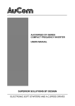
1.2.5 The Audio Output Zones and the Loudspeaker Circuit Fault Detector
Audio output is arranged to provide six user selectable zones as shown in figure 5. PTT1 always has the
highest priority and automatically selects all zone outputs where as if PTT1 is not active the highest priority
audio source can be routed to the required zones.
Figure 5. The Audio Output Zones
PTT1-4
1000
0XXX
0XXX
0XXX
0XXX
0XXX
0XXX
0XXX
0XXX
0XXX
ZA1ZA6
XXXXXX
000000
100000
010000
001000
000100
000010
000001
010101
111111
Zone
1A
Zone
1B
Zone
2A
Zone
2B
Zone
3A
Zone
3B
Zone
4A
Zone
4B
Zone
5A
Zone
5B
Zone
6A
Zone
6B
T*
T
T
T
T
T
T
T
T
T
T
T
T
T
T
T
T
T
T
T
T
T
T
T
T
T
T
T
T
T
T
T
T
T
T
T
T
T
T
T
T
T
* ‘T’ = Audible tone, ‘-‘ = No tone
The loudspeaker circuit fault detection works on a DC monitoring principle. An end-of-line resistor must be
fitted at the end of each loudspeaker circuit and the loudspeakers must be fitted with a de-coupling
capacitor. Please note “Emergency Broadcasts” will automatically go to ALL zones.
1.2.6 The Fault Reporting System
The fault indicator is integrated with a Liquid Crystal Display (LCD). The LCD module communicates with
the DSP and reports any fault detected. These faults are stored in a log; the operator can then retrieve the
log and inspect the last 100 logged faults.
The fault reporting system provides the following:
•
On detecting any fault the LCD or DSP activates a sounder, the sounder provides a minimum of 50dBA
SPL at any point one metre around the cabinet in normal operating conditions i.e. cabinet door closed.
•
On receiving a fault the System Fault LED begins to flash.
•
On receiving a fault the LCD indicates the nature of the fault or faults received. If more than 1 fault is
present the display will show the first fault, 1 of n (n is the number of faults received).
•
The sounder and LED continue to be active until all the faults have been accepted. The fault report will
not re-set itself in the case of intermittent faults.
•
On choosing the fault accept option (password protected), the sounder ceases and the fault LED
changes to an illuminated state. Any further new faults received cause the sounder to re-start, the LED
to flash and the new fault to be placed in the fault log.
•
If a fault has been logged and accepted (not reset), further occurrences of the same fault do not cause
the sounder to re-start.
•
Once a fault has been rectified it can then be cleared. When ALL faults have been cleared the System
Fault LED will be turned off and the LCD will return to “System Healthy”.
•
Any new detected fault causes the sounder to activate and the System Fault LED to flash.
•
A connection is provided to a PC Mimic program to allow changes to the system configuration.
JustiFire Installation, Operation and Service Guide
9
1.2.7 The Battery Charger
A battery charger system is provided which is monitored in accordance with the requirements of BS5839
part 8.
1.2.8 The Power Supply
The power supply for the unit is a 2 Amp (350W) nominal rating at 220/240V AC (4A at 110V AC). This is
adequate to supply the system and the amplifiers (at the rated 250-Watts load) and also to provide battery
charging capacity in accordance with the requirements of BS5839.
The power supplied to peripheral equipment (such as microphone stations) may have a substantial effect
on the sizing of batteries and power supply. Advice should be sought from the factory if peripherals are to
be powered from the main unit.
1.2.9 The Cabinet
The equipment complete with batteries is mounted in an IP63 rated wall cabinet with a swing door which is
key locked. The user terminations are all made onto 2 PCBs in the back of the box with the batteries
located in the bottom of the box. The modules for the system are mounted on a swing frame. Only the LCD
and keys can be accessed with the front door closed together with the LEDs which provide a backup
function in the event of a failure of the LCD.
JustiFire Installation, Operation and Service Guide
10
2. Unpacking
The JustiFire unit is packed in 5 main parts:
JustiFire cabinet complete with internal sub-rack
Amplifiers x 2
Module extraction key
12V batteries x 2
Battery termination and clamping kit consisting of:
One x Interconnecting bus bar
Four x M6 x 12mm bolts
One x Clamping bar
Check that the JustiFire packaging/unit components are undamaged and complete. In case of damaged or
missing components inform your supplier immediately and do not proceed with installation. To minimise
handling weight it is not recommended to assemble the unit prior to mechanical installation.
IMPORTANT:
Do not attempt installation or operation of the JustiFire unit before reading
the following installation guide and Fire Detection and Alarm Systems for
Buildings BS5839 parts 1, 4 & 8 thoroughly. For further information or
support contact your supplier.
JustiFire Installation, Operation and Service Guide
11
3. Mechanical Installation
Installation of the JustiFire unit should only be undertaken by personnel with the appropriate electrical and
mechanical qualifications.
When selecting a suitable mounting point consider the following points:
The JustiFire unit is IP63 rated and must be mounted in a suitable environment area out of direct
sunlight, and not directly exposed to heat or sources of ignition. The unit should have free ventilation
around it and the ventilation openings in the case should not be blocked or restricted.
Ensure that the wall is physically strong enough to bear the unit and suitable mounting bolts are used to
secure it. Avoid metal swarf or dust from entering the unit when drilling the wall for mounting.
WARNING: The weight of the JustiFire unit with batteries fitted is 70Kg. Extreme care
should be taken when lifting the unit to avoid personal injury.
The mounting location should be chosen to provide convenient routing of mains and signalling cables to
the top of the JustiFire cabinet.
Refer to figure 6. for the recommended mounting position. The unit should be mounted so that the front
door display is at eye level.
Figure 6. Recommended Mounting Details
JustiFire Installation, Operation and Service Guide
12
4. Electrical Installation
4.1 Connection of mains power
The power supply required is a clean 110 - 240 Volt, 50/60Hz. The unit is provided with three terminals for
incoming power, live (Brown), neutral (Blue) and earth (Green), located in the top of the box in the centre of
the back panel.
A domestic 13 Amp, 3-core cable is suitable. A dedicated 3 Amp spur should be used for the supply and it
may be preferred to use a fire resistant cable for this purpose. Ensure that the cable is disconnected from
the mains before beginning termination. The cable should be brought into the cabinet through a suitable
gland or grommet mounted in the top face, ensuring that the cable will not chafe on the side of the entry.
It should be noted that due to the comprehensive self-monitoring functions of JustiFire (both internally and
for the connected peripherals) if the unit is powered up with the associated field equipment connections
incomplete, the unit will immediately generate one or more alarms.
IMPORTANT:
Ensure the unit is properly earthed.
4.2 Connection of peripherals
All external signal connections are made to the Audio distribution PCB (see figure 7.) and the Termination
PCB (see figure 9.).
4.2.1 Connecting to the Audio Outputs
The JustiFire system provides terminations for 6 audio output zones with each zone having an ‘A’ and ‘B’
audio output pair. The position of these audio outputs on the audio distribution PCB are shown in figure 7.
Each pair of terminals is suitable for connecting a loudspeaker spur, so each amplifier can drive a minimum
of one and a maximum of 6 zones. It is recommended that loudspeaker layout and connection to the
JustiFire unit is made in accordance with BS5839 parts 1, 4 & 8.
Audio Output Terminations
Audio Output Zone Select Input Terminations
Figure 7. Audio Distribution Termination Details
JustiFire Installation, Operation and Service Guide
13
WARNING:
When the JustiFire unit is operational 100V AC audio signals may be
present on the audio output terminals. Always ensure the JustiFire unit is
isolated from the mains and battery supply at all times when connecting
to the audio outputs or making adjustments to the external wiring.
It is recommended that loudspeaker cables are fully tested before connection to the JustiFire unit. The
cables should be free from open-circuit, short-circuit and earth faults. The impedance of each loudspeaker
spur should be measured and recorded.
All external loudspeaker connections are monitored for fault conditions using DC so each loudspeaker
requires a suitable blocking capacitor fitting locally and EOL resistor fitted across the last loudspeaker on
the connected spur. Note: Recommended resistor value = 56kOhms 0.5W.
Excessive loudspeaker loading will not damage the unit, but it will mean that the battery and power supply
capacity is no longer adequate to conform with the requirements of BS5839.
4.2.2 Connecting to the Audio Output Zone Select Inputs
The position of the audio zone select inputs are shown in figure 7. Each audio zone output is individually
selectable via a volt free contact. Closing the appropriate contact pair will switch through the highest
priority audio to the matching ‘A’ and ‘B’ outputs as figure 5.
4.2.3 Connecting to the Fire Panel Inputs
The fire panel input terminals are located on the termination PCB as shown in figure 9. Five channels are
provided each configurable for two different modes of operation, volt free and voltage reversal. The fifth
channel operates as a de-latch control for momentary input signals.
The operating sense of these inputs may be configured using the Mimic software see section 6, ‘Software
configuration using the Mimic’.
Option A - 24V Voltage reversal mode
This wiring method is necessary for the system to be compliant with BS5839 Pt 8.
For this mode of operation, ensure the links listed in the table of figure 11 are removed.
WARNING: Failure to set these links correctly will result in system malfunction and
may result in system damage.
Connect the Fire Panel + / - leads to the FP+ and FP- / Com terminals on the appropriate JustiFire 5
pin block. If the JustiFire unit is the last device on this loop from the fire panel, connect an End-Of-Line
resistor as shown in figure 8 (see fire panel documentation for details of resistor value).
SCREEN
NO/NC
FP+
To Fire Panel +
FP-/COM
To Fire Panel -
EOL RES+
EOL RES-
End of Line
Resistor
Figure 8. Voltage Reversal End of Line Termination
JustiFire Installation, Operation and Service Guide
14
Fault Relay Terminations
Emergency Relay Terminations
Fire Panel Input Terminations
Audio Input Terminations
Figure 9. Termination PCB Connection Details
If there are other devices (e.g. sounders) further along this loop after the JustiFire unit, then connect
a continuing wire as shown in figure 10.
SCREEN
NO/NC
FP+
To Fire Panel +
FP-/COM
To Fire Panel -
EOL RES+
EOL RESTo Sounder -
To Sounder +
Figure 10. Voltage Reversal Intermediate Line Termination
JustiFire Installation, Operation and Service Guide
15
Fire
Panel
Input
Channel
Termination PCB
Version 72694004
Volt free
Operation
Termination PCB
Version 72694004
Voltage Reversal
Operation
Termination PCB
Version 5173031
Volt free
Operation
Termination PCB
Version 5173031
Voltage Reversal
Operation
1
2
3
4
5
Fit links:
J14, J15
J16, J17
J18, J19
J20, J21
J22, J23
Remove links:
J14, J15
J16, J17
J18, J19
J20, J21
J22, J23
Fit links:
JP9, JP10
JP7, JP8
JP5, JP6
JP3, JP4
JP1, JP2
Remove links:
JP9, JP10
JP7, JP8
JP5, JP6
JP3, JP4
JP1, JP2
Figure 11. Fire panel input configuration links
Option B – Volt Free mode
For volt free connections, the links listed in the table of figure 11 require fitting. Connect the contact
between the NO / NC and the FP- / COM terminals as shown in figure 12.
WARNING: Failure to set these links correctly will result in system malfunction and
may result in system damage.
SCREEN
NO/NC
To Fire Panel Contact
FP+
To Fire Panel Contact
FP-/COM
EOL RES+
EOL RES-
Figure 12. Volt Free line termination
4.2.4 Connecting to the Audio Inputs
The position of the audio inputs on the termination PCB is shown in figure 9. The JustiFire system provides
four audio inputs each individually selectable for 0db or 100V line input signals. These must be configured
using the table of figure 13 depending on the required input level.
WARNING: Failure to set these links correctly will result in system malfunction and
may result in system damage.
Audio
Input
Channel
Termination PCB
Version 72694004
0dB Operation
Termination PCB
Version 72694004
100V Operation
Termination PCB
Version 5173031
0dB Operation
Termination PCB
Version 5173031
100V Operation
1
2
3
4
Fit links:
J36 (1-2), J37 (1-2)
J32 (1-2), J33 (1-2)
J28 (1-2), J29 (1-2)
J24 (1-2), J25 (1-2)
Fit links:
J36 (2-3), J37 (2-3)
J32 (2-3), J33 (2-3)
J28 (2-3), J29 (2-3)
J24 (2-3), J25 (2-3)
Fit links:
JP25 (1-2), JP26 (1-2)
JP23 (1-2), JP24 (1-2)
JP21 (1-2), JP22 (1-2)
JP19 (1-2), JP20 (1-2)
Fit links:
JP25 (2-3), JP26 (2-3)
JP23 (2-3), JP24 (2-3)
JP21 (2-3), JP22 (2-3)
JP19 (2-3), JP20 (2-3)
Figure 13. Audio input configuration links
JustiFire Installation, Operation and Service Guide
16
Each of the audio input channels provides a ‘Press to talk’ (PTT) switch input, a “Talk now” (Tnow)
input, a “Busy” input and a 24Vdc supply output. These may be used to power and support external
audio equipment such as a microphone as shown in figure 15. The Tnow and “Busy” inputs are
suitable for driving an LED with a suitable dropping resistor. To power external equipment with 24Vdc
use the table of figure 14 to fit the appropriate links.
The operating sense of the PTT switch inputs may be configured using the Mimic software see section
6, ‘Software configuration using the Mimic’.
Audio
Input
Channel
Termination PCB
Version 72694004
24Vdc active
Termination PCB
Version 72694004
24Vdc inactive
Termination PCB
Version 5173031
24Vdc active
Termination PCB
Version 5173031
24Vdc inactive
1
2
3
4
Fit links:
J38, J39
J34, J35
J30, J31
J26, J27
Remove links:
J38, J39
J34, J35
J30, J31
J26, J27
Fit links:
JP17, JP18
JP15, JP16
JP13, JP14
JP11, JP12
Remove links:
JP17, JP18
JP15, JP16
JP13, JP14
JP11, JP12
Figure 14. Audio input 24Vdc configuration links
4.2.5 Connecting to the Emergency Relay
A set of volt free relay contacts are provided on the termination PCB, see figure 9, to allow external
monitoring of an emergency condition. Two isolated contacts are supplied each with a normally open,
normally closed and a common terminal connection. Check the electrical specification (section 10.) before
connecting external equipment to these contacts.
4.2.6 Connecting to the Fault Output Relay
A set of volt free relay contacts are provided on the termination PCB, see figure 9, to allow external
monitoring of fault conditions. Two isolated contacts are supplied each with a normally open, normally
closed and a common terminal connection. Check the electrical specification (section 10.) before
connecting external equipment to these contacts.
SCREEN
AUDIO +
MIC
CCT
AUDIO –
+24V
TNOW
Tnow
LED
BUSY
Busy
LED
PTT
OV COMMON
PTT Switch
Figure 15. Audio input termination of external microphone
JustiFire Installation, Operation and Service Guide
17
4.3 Connection of the Lead Acid Batteries
Two 12V lead acid batteries are supplied to provide a 24Vdc battery backup facility. These are packed
separately and require both mechanical and electrical installation. The batteries locate into the bottom of
the JustiFire cabinet and are held in position with the retaining clamp and nut supplied as shown in fig. 16.
Battery Retaining Clamp
Interconnecting Busbar
Black Wire
Red Wire
Battery 1
Negative
(BLACK)
Battery 2
Positive
(RED)
Battery 1
Figure 10. Battery connection and clamping
Positivedetails
(RED)
Battery 2
Negative (BLACK)
Figure 16. Battery Clamping and Connection Details
WARNING:
Before making any of the battery connections careful note should be
made of the polarity of the individual batteries relative to each other
and the battery charging leads, see figure 16. Extreme care should be
taken not to short the battery terminals to each other or the JustiFire
chassis.
Connect the two batteries together “in series” with the interconnecting bus bar and bolts supplied. Ensure
the JustiFire circuit breakers CB1-CB4 are all OFF and connect the red battery lead first followed by the
black. If the batteries require disconnecting at any time during installation ensure the reverse sequence is
adopted i.e. disconnect the black battery lead first. After connection, the batteries should be covered with
the cloth cover to protect the battery connections from external electrical shorts.
JustiFire Installation, Operation and Service Guide
18
5. Powering up the JustiFire for the first time
Before applying power to the JustiFire unit some final assembly is required. Insert the two amplifier
modules into the card frame behind the door. The amplifier modules are heavy and should be handled with
care to avoid mechanical damage. The modules should slide freely in the mounting rails of the frame and
only require slight pressure to finally locate enabling each module to be secured via the four fixing screws.
INFORMATION:
To remove any of the sub-rack modules, slacken the module retaining
screws and pull out the module using the module extraction key
provided.
Apply mains power to the unit and switch on the four circuit breakers in quick succession. The JustiFire unit
should adopt a standby status as defined in the table of figure 17. If the unit adopts a none standby status
and registers one or more alarms then refer to section 7 “Operation” to proceed with processing and
clearing them.
Figure 17. Standby Indication.
Module
Standby Indication Status
LCD Indicator Panel
LCD displays “System Healthy”, correct date & time. “POWER ON” LED
illuminated*.
Amplifier Module A (TOP)
“POWER ON”, “ACCESS” and “SELECT” LEDS illuminated
Amplifier Module B (BOTTOM)
“POWER ON”, “ACCESS” and “SELECT” LEDS illuminated
CFM Module
All Indicators off
Termination PCB
“COMMON FAULT”, “FP DELATCH”, “ALARM 1-4” and “PTT1-4”
illuminated**
*Note: All other module LEDS off unless stated otherwise, **Standby indication may change with software configuration
When the unit has adopted a standby status for the first time it is recommended to set up the current date,
time and user password via the front panel keypad (see “Operation” section).
JustiFire Installation, Operation and Service Guide
19
6. Configuration Using the MIMIC Software
6.1 General
The Mimic software is a PC based set-up program, which provides a quick tool for both configuration of the
user-defined parameters and monitoring of the JustiFire system. The mimic program will run on a Pentium
based PC with a 9-pin serial port and the Windows (95 or later) operating system.
6.2 Set-up
With the JustiFire unit powered down, configure the jumper J17 on the DSP card to “PC RS232”, and fit
jumpers JP10 ("CONFIG EEPROM WRITE") and JP9 ("FLASH WRITE") and then replace in the rack.
Alternatively, if the DSP has "RUN/CONFIG" switch, set it to the "CONFIG" position and the "KEYPAD/PC"
switch to the "PC" position. Connect the PC serial port to the serial connector on the front of the JustiFire
DSP card using a 9-pin “one-to-one, straight through” male/female serial lead. Power up the JustiFire unit
and run the Mimic program.
INFORMATION:
Set Jumper J17 to “PC RS232” on the DSP card (or the switch to "PC")
to allow mimic configuration, or “KEYPAD TTL” (switch to "KEYPAD")
for normal operation. Fit jumper JP10 (or switch to "CONFIG") to
change the configuration and fit JP9 to change the message store.
Remove both JP10 (or switch to "RUN") and JP9 for normal operation.
Note: During communications with the Mimic software the JustiFire keypad and fault relay will register a
system fault which may be ignored.
6.3 Operation
On running the Mimic program the user will be presented with the option to run the Mimic in Real or Dummy
mode as figure 18. In “Real” mode the Mimic software has control over the JustiFire configuration
parameters and will display real time information where as “Dummy” mode is a standalone presentation of
the Mimic screens with prefixed data. To continue with system configuration select “Real” and press the
“OK” button.
Figure 18. Mimic mode dialogue box
Figure 19. Display of Communication Errors
6.4 The Main Screen
After selection of the Mimic mode the user will be presented with the main Mimic screen as shown in figure
20. This gives a system over-view and provides access to the main user configurable options in the system.
General Mimic information and set-up is accessed through the top menu where as specific JustiFire
parameters are accessed by clicking on the appropriate symbol in the main area of the screen. Alternatively
if communications with the JustiFire rack is not established the user will be presented with the display of
figure 19. In this case check the PC COM port configuration and the serial lead connections.
JustiFire Installation, Operation and Service Guide
20
Figure 20. The main Mimic screen
6.5 The Menu Options
6.5.1 “Connection Settings”
If the PC serial COM port will not support the default settings of COM1 and 19200 Baud rate then these
may be changed to those shown in figure 21. Press the “OK” button to confirm the new settings.
Figure 21. The Connections settings dialogue box
6.5.2 “Allow Set-up”
To gain access to and change the JustiFire configuration settings the user must first enable this option by
clicking on the “Allow Set-up” menu option. When active a tick will appear when this menu option is viewed.
6.5.3 “Change Password”
The password function is currently inoperable.
JustiFire Installation, Operation and Service Guide
21
6.5.4 “About JustiFire Mimic”
This option displays the Mimic software version number.
6.5.5 “JustiFire Information”
This option displays further Mimic software release information.
6.5.6 “JustiFire IO”
This option displays a mixture of user and diagnostic information as shown in figure 22 and described as
follows:
Reset count:
Input Low:
Input High:
Links:
FPGA:
ADC A:
ADC B:
The number of times the DSP IC has been reset by the system watchdog.
Diagnostic Information.
Diagnostic Information.
The current DSP links, which are fitted.
The version of the FPGA IC fitted to the DSP card.
Diagnostic Information.
Diagnostic Information.
Figure 22. JustiFire IO information
6.5.7 “Fault Control”
Selecting this menu option displays 2 options as shown in figure 23 which allow the user to override the
normal fault handling procedures of the JustiFire system.
Figure 23. Fault control dialogue box
The fault control parameters are:
All faults Accepted:
allows the user to take all outstanding unaccepted alarms to an accepted
state and silence the JustiFire buzzer.
All faults Cleared:
allows the user to clear all accepted alarms.
JustiFire Installation, Operation and Service Guide
22
6.6 Changing the JustiFire Parameters
When the JustiFire is first installed the Mimic software can be used for configuration of all the JustiFire
parameters. A limited number of these non-emergency based parameters may also be configured directly
through the JustiFire keypad (see “Operation” section) where indicated.
WARNING: When the JustiFire unit is powered up, if jumper JP8 is fitted the unit will
adopt the factory default parameters. After any of the parameters have been
changed ensure that the jumper JP8 on the DSP card has been removed
before cycling the power, otherwise the new settings will be overwritten by
factory defaults.
6.6.1 Changing the PTT1 Options
Clicking on the PTT1 icon displays an options box as shown in figure 24.
Figure 24. PTT1 options dialogue
box
The individual PTT parameters are:
Priority:
Sense:
Silence Sounder:
Emergency Broadcast:
Chime:
The priority of the PTT1 input is fixed at the highest level as this is reserved
for use with the fireman’s microphone.
The sense of the PTT1 input can be selected to be active high or low.
This option will cause an active PTT1 input signal to silence the JustiFire
buzzer.
This option will cause an active PTT1 input signal to generate an emergency
broadcast.
This allows for the selection of various pre-announcement chimes.
6.6.2 Changing the PTT2-4 Options
Clicking on the PTT2-4 icons give a similar set of options to that for PTT1 except the user has access to set
the input priority but not the Silence Sounder option as shown in figure 25.
JustiFire Installation, Operation and Service Guide
23
Figure 25. PTT2 dialogue box.
The default parameters for the PTT Inputs, the Alarm Inputs and the Monitoring are shown on figure 26
Input Type
Emergency
Broadcast
Silence
Sounder
Default
Priority
Monitoring
Chime
Audio Input 1/PTT1
Message Input 1
Audio Input 2/PTT2
Message Input 2
Audio Input 3/PTT3
Message Input 3
Audio Input 4/PTT4
Message Input 4
On
On
Off
Off
Off
Off
Off
Off
On
-
1 (Fixed)
2
3
4
5
6
7
8
30 Hz
30 Hz
30 Hz
30 Hz
-
None
None
None
None
None
None
None
None
Figure 26. The default parameter settings for PTT1-4 and Message 1-4 inputs.
6.6.3 Changing the Message Input 1-4 Options
Clicking on any of the Message icons displays an options box as shown in figure 27.
Figure 27. PTT1 options dialogue box
The individual message input parameters are:
Priority:
Sense:
Emergency Broadcast:
Chime:
The priority of this Message input relative to the other 3 and also the PTT1-4
inputs may be selected.
The sense of the Message input can be selected to be active high or low.
This option will cause an active Message 1 input signal to generate an
emergency broadcast.
This allows for the selection of various pre-announcement chimes.
JustiFire Installation, Operation and Service Guide
24
6.6.4 Changing the Audio Input 1-4 Options
Clicking on any of the Audio input icons displays an options box as shown in figure 28. Each audio input is
equipped with the option to select the fault monitoring method and a gain control allowing the volume level
to be set/adjusted. Selection of the required fault monitoring tone will bring up a further window to allow the
fault monitoring to be set-up as shown in figure 29.
Figure 28. Audio input options dialogue box
Figure 29. Audio input monitoring options dialogue box
The individual monitoring parameters are:
Set Point:
Scale:
Fault Timeout:
This slider sets the trip point below which a monitoring failure alarm will be
raised subject to the Fault Timeout option setting.
The current level of the monitoring tone can be measured by selecting each
scale option in turn until the peak of the signal is displayed.
This option sets the time the monitoring level must remain below the trip point
before a monitoring failure alarm will be raised.
6.6.5 Changing the Voice Storage Options
Clicking on any of the four VSM (Voice Stored Message) icons displays a dialogue box as shown in figure
30. The primary slider option allows for the volume of the individual message to be adjusted while the
buttons on this window also allow for message recording and functionality options. Clicking the “Message”
button produces a dialogue box as shown in figure 31.
INFORMATION: Fit jumper JP9 to enable the overwritting of the existing messages by
the downloading of a "*.wav" file.
Remove JP9 for normal operation thus eliminating memory corruption
JustiFire Installation, Operation and Service Guide
25
Figure 30. VSM options dialogue box
Figure 31. VSM set-up options dialogue box
The individual message functions are:
Load Sound From File:
Save Sound To File:
Play Sound File:
1Khz Tone:
Intermittent 1Khz Tone:
Bell:
This feature allows the loading of a new message, in *.wav format from a file
of the users choice, to overwrite the existing message.
This feature allows the existing message to be saved *.wav format to a file of
the users choice.
This feature allows the user to play/review *.wav sound files.
This feature replaces the current message with a constant 1Khz tone.
This feature replaces the current message with a continuous cycle of 1Khz
tone for 1 second followed by 1 second of silence.
This feature replaces the current message with a bell tone.
Clicking the “Timing” button produces a dialogue box as shown in figure 32:
Figure 32. VSM timing options dialogue box
The individual timing functions are:
Hold Off Time:
Repeat Time:
This parameter controls the delay in seconds (0-255) after the message input
becomes active before the message starts to play regardless of the Playback
mode.
This parameter controls the delay in seconds (0-255) before the message
repeats during Periodic Repeat Playback mode.
JustiFire Installation, Operation and Service Guide
26
The Playback Mode options are:
Continuous:
Periodic Repeat:
One Shot:
Non-Latch:
This mode causes the message to play continuously with no inter message
delay.
This mode causes the message to play continuously with an inter- message
delay set by the Repeat Time setting.
This mode causes the message to play once only.
This mode activates the message during an active input only.
The Priority Block feature inhibits the playing of lower priority messages whilst a higher priority message is
inactive (pausing) during the repeat time.
6.6.6 Changing the Input Controller Options
Clicking on the left-hand box of the two boxes displayed centrally in the main screen produces the
Controller Set-up dialogue box as shown in figure 33. This dialogue box provides an overall summary of all
the system input priorities previously defined and allows the priority of each to be changed.
Figure 33. Controller Set-up dialogue box
6.6.7 Changing the Audio Controller Options
Clicking on the right-hand box of the two boxes displayed centrally in the main screen produces the Audio
Controller Set-up dialogue box as shown in figure 34. This dialogue box provides access
Figure 34. Audio Controller Set-up dialogue box
JustiFire Installation, Operation and Service Guide
27
to all the volume control settings for the system components. These are:
Inp1-4:
Msg1-4:
Chime:
Output:
30Hz level:
The input levels of the audio inputs 1-4.
The output levels of the messages 1-4.
The output level of the pre-announcement and pre-message chimes.
The output level of the selected system audio output (audio input or message).
The output level of the 30 Hz monitoring signal.
6.6.8 Changing the Amplifier Options
Clicking on one of the amplifier rectangles on the main display produces the dialogue box as shown in
figure 35. This dialogue box allows adjustment of the parameters controlling the 30 Hz monitoring for the
chosen amplifier. The individual monitoring parameters are:
Set Point:
Scale:
Fault Timeout:
This slider sets the trip point below which a monitoring failure alarm will be
raised subject to the Fault Timeout option setting.
The current level of the monitoring tone can be measured by selecting each
scale option in turn until the peak of the signal is displayed.
This option sets the time the monitoring level must remain below the trip point
before a monitoring failure alarm will be raised.
Figure 35. Amplifier 1 Set-up dialogue box
6.6.9 Changing the Emergency Options
Clicking on the “Emergency” icon displays the Emergency dialogue box as shown in figure 36. This
dialogue box provides an overall summary of which inputs to the system have been classified with an
“Emergency” status and allows this status to be changed.
Figure 36. Emergency Set-up dialogue box
JustiFire Installation, Operation and Service Guide
28
7. Operation
The JustiFire is operated using the 3 keys on the front of the unit, ‘▲’ (SCROLL UP), ‘▼’ (SCROLL
DOWN) and ‘ENTER’, together with a 4 line Liquid Crystal Display (LCD).
There are also four indicators (LEDs) on the front of the unit, which together with a buzzer indicate the
current status of the system in compliance with BS5839 Part 8.
7.1 The Status Indicators
7.1.1 ‘SYSTEM FAULT’ (Yellow LED)
If the system is healthy (fault free) the ‘SYSTEM FAULT’ indicator will be unlit. In this case the LCD will also
normally be unlit and the buzzer will be silent.
If the system has an unaccepted fault the ‘SYSTEM FAULT’ indicator will flash. In this case the LCD will be
lit showing the current fault(s) and the buzzer will sound.
If the system has faults which are then all accepted then the ‘SYSTEM FAULT’ indicator will change from
flashing to being constantly lit. In this case the LCD will remain lit showing the accepted fault(s) and the
buzzer will be silenced.
7.1.2 ‘DISPLAY FAULT’ (Yellow LED)
In normal operation the ‘DISPLAY FAULT’ indicator will be unlit. If however the display loses
communications with the Digital Signal Processor (DSP), then it will become lit. In this case the LCD will be
lit showing a ‘Comms Error’, the ‘SYSTEM FAULT’ indicator will also be lit and the buzzer will sound.
7.1.3 ‘POWER ON’ (Green LED)
The JustiFire requires a constant 24 Volt DC supply to operate. This is provided by the power supply unit in
normal operation, whilst in the event of a mains failure or a power supply problem the 24 Volts is provided
by the battery backup (two 12 Volt batteries). So, in normal operation (or whilst using battery backup), the
‘POWER ON’ indicator will be illuminated.
7.1.4 ‘FALLBACK’ (Yellow LED)
In normal operation the ‘FALLBACK’ indicator should be unlit. If however the DSP (which contains the main
control software) fails, in compliance with BS5839 Part 8, the Fireman’s microphone can still be used and in
this case the ‘FALLBACK’ indicator will be illuminated.
Note that whilst in the ‘FALLBACK’ mode, only the Fireman’s microphone is operative.
7.2 Normal Operation (Healthy State)
On power-up, assuming the system is fault-free the LCD will be unlit and will display the current healthy
status together with the current date and time, which updates every second, as shown in figure 37.
System Healthy
27/06/01
14:05:31
Figure 37. System Healthy Status
Also, whilst healthy, the ‘SYSTEM FAULT’, ’DISPLAY FAULT and ‘FALLBACK’ indicators will all be unlit
and the buzzer will be silent. The ‘POWER ON’ indicator will be the only LED which is lit.
JustiFire Installation, Operation and Service Guide
29
7.3 On Receipt of a Fault
If a fault is received whilst the system is in a healthy state, the ‘SYSTEM FAULT’ indicator will start to flash
and the LCD will become lit showing details of the current fault(s) as shown in figure 38. The first two lines
show the type of fault, the third line shows the current status of the fault (On, Latched or Accepted), whilst
the last line shows the number of current faults, i.e. the first number shows the index of this particular fault
while the second number shows the total number of current faults. To view the other current faults, use the
‘▲’ and ‘▼’ keys to scroll through the list.
DPU
Comms Error
On
Fault 01/ 01
Figure 38. Display of Fault condition
Faults which have come and gone without being accepted are designated as being ‘Latched’.
Also note that whilst the system has an unaccepted fault the buzzer will sound.
7.4 Password Protected Mode
The ability to accept or clear a fault, to look at historical data or to change the date, time or password can
only be done in protected mode, which is protected by use of a password.
From either the ‘System Healthy’ display or the ‘Current Fault’ display pressing the ‘ENTER’ key will then
illuminate the display which will then ask for a 3 number password as shown in figure 39. The password is
user configurable and is initially set at the factory as 09: 09: 09.
Enter Password
00: 00: 00
Figure 39. Display of Password Entry
The password consists of three numbers with each number having a value between ‘00’ and ‘09’. Set the
first, highlighted number by using the ‘▲’ and ‘▼’ keys to alter the number between ‘00’ and ‘09’. Once the
first number is set press the ‘ENTER’ key to highlight the second number. Likewise set the second and
third numbers and after the third number is selected and the ‘ENTER’ key pressed if a valid password has
been entered a key symbol will appear in the bottom right hand corner signifying protected mode. The
display will now show a list of options available with the ‘3’ symbol indicating the current choice as shown
in figure 40.
Accept Fault
Clear Fault
3
Ñ
Figure 40. Display of Top Level Menu
Other options in the list include Event Log, Set Date, Set Time, Accept Timeout, New Password, DSP
Links, DSP Resets and Exit.
JustiFire Installation, Operation and Service Guide
30
The ‘▲’ and ‘▼’ keys are used to scroll up and down the list of options and the ‘ENTER’ key is used to
select the chosen option.
If a valid password is entered the system will remain in protected mode for two minutes without the need to
re-enter the password. After the two minutes have elapsed the system will automatically return to the
original ‘System Healthy’ or ‘Current Fault’ display and the key symbol will disappear.
Likewise if an invalid password is entered the system will also return to the original ‘System Healthy’ or
‘Current Fault’ display.
7.5 Accepting a Fault or ‘What to do when the fault buzzer sounds’
•
Read the details on the display and make a note of the fault description.
•
If there is more than one fault, then scroll through the faults using the ‘▲’ and ‘▼’ keys.
•
•
Display the fault that is to be accepted.
Enter protected mode and choose the ‘Accept Fault’ option as described in section 7.4. The display will
then ask whether the fault is to be accepted (Y/N) as shown in figure 41.
Accept Fault
Y▲
N▼
Ñ
Figure 41. Display of Accept Options
•
•
•
Press the ‘▲’ or ‘▼’ key to accept the fault or not. The display will then return to the list of current
faults. If the fault has been successfully accepted the third line on the current fault display for that
particular fault will now read ‘Accepted’. If all the current faults have been accepted the buzzer will now
stop and the ‘SYSTEM FAULT’ indicator will change from flashing to being continually lit. If they do not,
then there is still a fault to be accepted, so continue to scroll through the list to find this unaccepted
fault.
Arrange for appropriate repair / maintenance of the system.
Once all faults have been accepted the system allows up to 24 hours for the faults to be rectified. The
default setting for this ‘Accept Timeout’ is 24 hours, so in this case, when the 24 hours have elapsed the
‘Accepted’ faults are reset to ‘On’ and the buzzer sounded again.
7.6 Clearing a Fault or ‘What to do when a fault has been fixed’
•
•
•
Accept the fault as described in section 7.5.
Display the fault that is to be cleared.
Enter protected mode and choose the ‘Clear Fault’ option as described in section 7.4. The display will
then ask whether the fault is to be cleared (Y/N) as shown in figure 42.
•
Press the ‘▲’ or ‘▼’ key to clear the fault or not. The display will then return to the list of current faults.
If the fault has been successfully cleared the fault should no longer appear in the list of current faults. If
all the faults have been cleared the ‘SYSTEM FAULT’ indicator and the LCD will in normal operation be
unlit and the LCD will display ‘System Healthy’.
If the fault is still present, the buzzer will sound, and the fault should be accepted again.
•
Clear Fault
Y▲
N▼
Ñ
Figure 42. Display of Clear Options
JustiFire Installation, Operation and Service Guide
31
7.7 Viewing the Event Log
•
Enter protected mode and choose the ‘Event Log’ option as described above in section 7.4.
•
The Event Log contains the 100 most recent events and these can be displayed in turn by using the ‘▲’
and ‘▼’ keys to scroll through the list. Each event is given a time stamp when the event occurred and is
also given an index number in the list of 100 events as shown in figure 43.
27/06/01 14:17:28 01/100
DPU
Comms Lost
Raised
Ñ
Figure 43. Display of Log
The first line shows the date and time at the moment the event occurred together with the index
number. The second and third lines show the event type and the last line shows the status of the event.
•
Pressing the ‘ENTER’ key will exit from the ‘Event Log’ to the previous menu display.
7.8 Setting the Date and Time
•
•
Enter protected mode and choose either the ‘Date’ or ‘Time’ option as described in section 7.4.
If the ‘Date’ option is chosen the current system date is displayed e.g. 29/ 06/ 01 and likewise the ‘Time’
option will display the current system time e.g. 14: 25: 31. As described previously in section 7.4, each
number can be set (when it is highlighted) by using the ‘▲’ and ‘▼’ keys while the ‘ENTER’ key is
used to move from day to month to year or from hours to minutes to seconds. Once either the year or
the seconds have been set and the ‘ENTER’ key pressed the operator is asked whether any changes
are to be saved as shown in figure 44.
Save Changes?Y ▲
N▼
Ñ
Figure 44. Display of Save Date/Time
•
Press the ‘▲’ or ‘▼’ key to set the Date/Time or not. If ‘Y’ is selected the display will confirm if the
Date/Time has been saved OK. The display will then return to the protected mode menu.
7.9 Changing the Timeout for the resetting of Accepted Faults
•
•
Enter protected mode and choose ‘Accept Timeout’ as described above in section 7.4.
The first number displays the current setting for the Timeout in hours (the minutes and seconds are not
currently used) as shown in figure 45. The hours can be set from 0-24 by using the ‘▲’ and ‘▼’ keys.
Note: A setting of 0 disables resetting, while the factory default setting is 24 hours, i.e. the ‘Accepted’
faults will be reset to ‘On’ after 24 hours and the buzzer re-sounded.
Accept Timeout
24: 00: 00
Ñ
Figure 45. Display of Accept Timeout
JustiFire Installation, Operation and Service Guide
32
•
Press ‘ENTER’ to save this new setting.
Save Changes?Y ▲
N▼
Ñ
Figure 46. Display of save Accept Timeout
•
Press the ‘▲’ or ‘▼’ key to save the new Timeout or not as shown in figure 46. If ‘Y’ is selected the
display will confirm if the Timeout has been saved OK as shown in figure 47. Upon pressing ‘ENTER’
(or if ‘N’ had been previously selected) the display will return to the previous protected mode menu.
Save OK
24 Hours
ENTER to Exit
Ñ
Figure 47. Display of Save OK message
7.10 Changing the User Password
•
Enter protected mode and choose ‘New Password’ as described in section 7.4.
•
As described previously in section 7.4, the password consists of three numbers and each number can
be set in turn (when it is highlighted) by using the ‘▲’ and ‘▼’ keys and once set the ‘ENTER’ key is
used to move on to the next number as shown in figure 48.
•
When the third number is set and the ‘ENTER’ key is pressed the display will return to the previous
protected mode menu.
New Password
00: 00: 00
Ñ
Figure 48. Display of New Password Entry
•
The new password then needs to be confirmed before it is saved in the system memory. To confirm
the new password select the ‘New Password’ option again but this time it will ask for the password to be
confirmed as shown in figure 49.
Confirm Password
00: 00: 00
Ñ
Figure 49. Display of Confirm Password Option
•
Enter the same password as before and this time if the two password entries match the new
password will be committed to the system memory.
•
Again, when the third number is set and the ‘ENTER’ key is pressed the display will return to the
previous protected mode menu.
JustiFire Installation, Operation and Service Guide
33
7.11 Viewing the DSP Links information
•
Enter protected mode and choose the ‘DSP Links’ option as described in section 7.4.
•
The display will now show details of the eight DSP configuration links (JP1 – 8). If the link is fitted there
is a ‘Y’ beneath the appropriate number and ‘N’ if it is not fitted as shown in figure 50.
DSP Links
1 2 3 4 5 6 7 8
Y Y Y N N N N N
ENTER to Exit
Ñ
Figure 50. Display of DSP Link Information
DSP Links JP1 – JP8
These links are inputs to the DSP and are used to control various software functions as described in
the table in figure 51.
•
When the ‘ENTER’ key is pressed the display will return to the previous menu.
Link Ref
JP1
Function
JP5
Enable monitoring on audio input 2 (FITTED for standard JustiFire
operation)
Enable monitoring on audio input 3 (FITTED for standard JustiFire
operation)
Enable monitoring on audio input 4 (FITTED for standard JustiFire
operation)
200W option enables extra PSU faults (UNFITTED for standard
JustiFire operation)
FITTED = VeriFire, UNFITTED = JustiFire
JP6
Enable fallback mode (UNFITTED for standard JustiFire operation)
JP7
Enable message synchronisation (UNFITTED for standard JustiFire
operation)
Cold start (resets config. EEPROM to factory defaults and disables
watchdog reset) (UNFITTED for standard JustiFire operation)
JP2
JP3
JP4
JP8
Figure 51. DSP link details.
JustiFire Installation, Operation and Service Guide
34
7.12 Viewing the Number of DSP Resets
•
Enter protected mode and choose the ‘DSP Resets’ option as described above in section 7.4.
•
In order to comply with BS5839 Part 8 the system indicates how many times the DSP has been
internally reset since it was last powered up as shown in figure 52.
Resets
000
ENTER to Exit
Ñ
Figure 52. Display of DSP Reset Count
•
When the ‘ENTER’ key is pressed the display will return to the previous menu.
7.13 Exiting the Protected Mode Menu
From the protected mode menu upon choosing the ‘Exit’ option as described in section 7.4, the system will
return to the original ‘System Healthy’ or ‘Current Fault’ display.
7.14 Keypress Timeout
Whilst in protected mode if a key is not pressed within 30 seconds the system will automatically return to
the original ‘System Healthy’ or ‘Current Fault’ display.
JustiFire Installation, Operation and Service Guide
35
8. Service & Maintenance
The JustiFire unit requires little maintenance but for total system integrity the following service schedule, in
accordance with BS5839 : Part1 : 1998, is recommended at the stated intervals.
8.1 Daily Checks
•
Check the unit gives the correct standby indication and status as described in section 5 and figure 17.
Check the “System Fault” LED, see section 7.1.1, the LCD display and any external fault indication
equipment if connected and if any fault is present, investigate and remedy as required.
8.2 Weekly Checks
•
Activate the system via the fire detection system and check for the correct output from all loudspeaker
zones. If any loudspeaker or zone proves inoperable or sub standard, investigate and remedy as
required.
•
Perform a visual inspection of the batteries and the associated connections and ensure they are in good
condition. Remedy any defect as required.
8.3 Quarterly Checks*
•
Check the JustiFire cabinet/seals for damage/wear, which may affect the units IP rating and overall
immunity to the ingress of contaminates. Ensure any ingress of contaminates is cleaned away and any
damaged or worn seals are replaced.
•
Check the JustiFire cabinet ventilation apertures are not blocked so as to maintain adequate ventilation
for system cooling and battery charging.
*Note: Testing of the batteries at this interval is not required as the JustiFire system performs it’s own periodic battery test.
8.4 Five Yearly Maintenance
•
All wiring to/from the JustiFire cabinet should be inspected/checked as part of the buildings overall IEEE
inspection and test requirement.
•
Change both lead acid batteries ensuring the replacements are of a similar specification.
•
Change the audio distribution PCB relays K1-K6 ensuring the replacements are of a similar
specification.
JustiFire Installation, Operation and Service Guide
36
9. Troubleshooting
The following section describes remedies to installation and configuration issues. If the fault is not listed or
remains active, contact your supplier for further assistance.
9.1 No Audio Output from the System
9.1.1 No Microphone Audio
•
If the microphone requires power from the JustiFire rack ensure the appropriate Field Power links are
fitted, see section 4.2.4 and figure 14.
•
Ensure the appropriate PTT input is active and changes in this input can be seen with the appropriate
PTT LED on the termination PCB. Also ensure the PTT set-up is correct paying particular attention to
the signal sense, see sections 6.6.1 and 6.6.2.
•
Check the audio input level links are set correctly, see section 4.2.4 and figure 13.
•
Check the microphone volume setting is adequate, see sections 6.6.4 and 6.6.7.
•
If other audio channels are active check the overall priority structure, see section 6.6.6.
•
Check the target loudspeaker zone is selected via the audio distribution inputs, see section 4.2.2 and
figure 5.
•
If any amplifier or loudspeaker circuit alarms are present clear them down and review the microphone
audio again, see section 7.3.
9.1.2 No Message Audio
•
Ensure the appropriate fire panel input is active and changes in this input can be seen with the
appropriate Alarm LED on the termination PCB. Also ensure the fire panel input set-up is correct paying
particular attention to the mode of operation, see sections 4.2.3.
•
Check the message volume setting is adequate, see sections 6.6.5 and 6.6.7.
•
If other audio channels are active check the overall priority structure, see section 6.6.6.
•
Check the target loudspeaker zone is selected via the audio distribution inputs, see section 4.2.2 and
figure 5.
•
If any amplifier or loudspeaker circuit alarms are present clear them down and review the message
audio again, see section 7.3.
JustiFire Installation, Operation and Service Guide
37
9.2 Alarm Messages
9.2.1 Circuit Fault Monitoring Alarms
• Amp 1 Short CCT:
Check all external “A” loudspeaker circuits for short circuits between the two
signal conductors and check for correct termination to the JustiFire rack.
• Amp 2 Short CCT:
Check all external “B” loudspeaker circuits for short circuits between the two
signal conductors and check for correct termination to the JustiFire rack.
• Amp 1 Open CCT:
Check all external “A” loudspeaker circuits for open circuits on either of the
two signal conductors and check for correct termination to the JustiFire rack.
Ensure the correct termination resistors are fitted to the loudspeaker circuits.
• Amp 2 Open CCT:
Check all external “B” loudspeaker circuits for open circuits on either of the
two signal conductors and check for correct termination to the JustiFire rack.
Ensure the correct termination resistors are fitted to the loudspeaker circuits.
• Amp 1 Earth Leak:
Check all external “A” loudspeaker circuits for short circuits between either of
the two signal conductors and screen or the earthed building metalwork. Also
check for correct termination to the JustiFire rack.
• Amp 2 Earth Leak:
Check all external “B” loudspeaker circuits for short circuits between either of
the two signal conductors and screen or the earthed building metalwork. Also
check for correct termination to the JustiFire rack.
9.2.2 System Fault Monitoring Alarms
• Audio Input 1-4 Alarms:
Check the audio 1-4 monitoring alarm set points, see section 6.6.4.
• Amp 1 Power/Signal Fault:
Check circuit breaker CB2 is closed and amplifier power lead (TB4) is
plugged into sub-rack motherboard.
• Amp 2 Power/Signal Fault:
Check circuit breaker CB3 is closed and amplifier power lead (TB6) is
plugged into sub-rack motherboard.
• Amp 1/2 Audio Fault:
Check both the amplifiers monitoring alarm set points, see section
6.6.8.
•
Check the mains supply to the JustiFire rack and any associated
fusing.
PSU Mains/Charger Fail:
• Battery Low/Disconnected:
Check circuit breaker CB4 is closed and the battery leads are
connected correctly, see section 4.3.
JustiFire Installation, Operation and Service Guide
38
10. Specification
Cabinet Dimensions: Height x Width x Depth
Weight
Mains Supply Voltage
Battery Supply
Fire Panel Inputs
Audio Inputs
Zone Select Inputs
Audio Outputs
Emergency Relay Contacts
Fault Relay Contacts
Audio Distribution Relays K1-K6
Certifications
650 x 600 x 255mm
70Kg
Voltage range: 90-264V AC
Frequency range: 47-63Hz
Current: 0.75A Standby, 2.5A with 250W load
2 x 12V 44Ah (dimensions: 200x170x165mm)
4 Channels + delatch:
Support for volt free contact or 24Vdc voltage reversal.
4 Channels:
Support for 0db or 100V line audio input +
24Vdc@ 100ma field power+
PTT input accepts volt free contact
6 Inputs:
Accepts volt free contact.
6 Zones:
Dual 100V line outputs per zone + support for O/C, S/C & earth
fault detect
2A @ 30V DC, 0.5A @ 125V AC
Max switch voltage: 220V DC, 240V AC
2A @ 30V DC, 0.5A @ 125V AC
Max switch voltage: 220V DC, 240V AC
Shrack RTE24024 DPCO 8A/24V
EN50130-4: 1995
EN55022: 1998 Class B
EN50081-1:1992
EN61000-3-3: 1995
EN61000-3-2: 1995 + A1 + A2
Complies to BS5839 Parts 1, 4 & 8
JustiFire Installation, Operation and Service Guide
39
11. Appendix A: Message Definitions
Evacuation Message D1VM0005: -“Tone. Attention please. This is a fire emergency, please evacuate the building by
the nearest available exit. Do not use the lifts, go to the assembly area.”
System message store 1, DSP IC ref J1, csum: 05BAC67A
Alert Message D1VM0006: - “Tone Tone Tone. Attention please. We are investigating an alarm condition. It may
be necessary to evacuate the building. Please stay on alert and await further
information.”
System message store 2, DSP IC ref J2, csum: 04A3C0C4
All Clear Message D1VM0003: -“Bing Bong. May I have your attention please, may I have your attention please. The
safety systems are now back to normal. Thank you for your co-operation and we
apologise for any inconvenience.”
System message store 3, DSP IC ref J3, csum: 059E0E88
Test Message D1VM0004: -
“Bing Bong. This is a test of the public address system. This is a functional test for
operation, loud loudspeaker coverage, signal level and speech intelligibility.”
System message store 4, DSP IC ref J4, csum: 06467B84
Format:
wav file, 12kHz, Mono, wave-signed 16 bit, maximum length 40 seconds.
JustiFire Installation, Operation and Service Guide
40