1
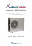
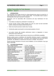
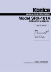
EN
HEATING PUMP FOR SWIMMING POOLS
(THP05 - THP30s)
INSTALLATION
AND USER MANUAL
EN
Contents
I.
II.
III.
IV.
V.
VI.
VII.
VIII.
IX.
X.
Applications ...................................................................4
Characteristics ................................................................4
Technical parameters .....................................................4
Dimensions . ..................................................................5
Directions for installation . ............................................6
Operating instructions . ..................................................8
Testing . .........................................................................10
Safety precautions . .......................................................10
Maintenance ................................................................. 11
Solving common malfunctions .................................... 11
Thank you for choosing our product and trusting our company. To ensure that using this product brings
you joy, please read the instructions carefully and follow the user manual exactly before use, to prevent
equipment damage or unnecessary injuries.
2
EN
I. Applications
1. To set up an effective and economic pool temperature that it is comfortable and pleasant for you.
2. The user can select the model’s technical parameters according to the professional manual. Pool heating was optimised in the factory (see table with technical parameters).
II. Characteristics
1.
2.
3.
4.
5.
6.
7.
8.
Highly effective titanium heat exchanger
Sensitive and accurate temperature regulation. Water temperature display
Ecological coolant R407c
Protection against high and low pressures
Automatically switches off when it goes below the minimum temperature
Forced anti-freezing with regulation temperatures
Air pump of international trademark
Easy installation and operation
III. Technical parameters
Model
Input in kW
Heating performance
in kW
Efficiency
Infeed
Rated current/ Max.current in A
Sound dB(A)
Net weight/ Gross weight
in kg
Specifications for water
supply and discharge
piping in mm
Recommended water flow
m3/h
THP05
0,7
THP06
0,93
THP09
1,4
THP12
1,8
THP16
2,4
THP23
3,7
THP23s
3,7
THP30s
4,5
5
6
9
12
16
23
23
30
≥ 6,2
≥ 6,2
≥ 6,2
≥ 6,2
≥ 6,2
for one phase 220 - 240V~50Hz
4,6/6,4
4,6/6,4
6,4/8,2
8,2/11
≤ 48
≤ 48
≤ 48
≤ 48
≤ 50
45/50
45/50
52/57
65/70
50
50
50
≥3
≥3
≥3
≥ 6,2
10,9/14,1 17,5/26,5
≥ 6,2
≥ 6,2
3N-380V~50Hz
5,6/8,5
6,8/9,5
≤ 56
≤ 56
≤ 58
85/93
102/110
102/110
123/133
50
50
50
50
50
≥5
≥ 6,5
≥ 10
≥ 10
≥ 10
Warning:
1. This product can work satisfactorily in a water temperature range of +5°C to +40°C and at an air
temperature of +7° to +40°C; outside these ranges, it will not be efficient. Please note that pool heating
performance and its parameters vary according to conditions.
2. On the grounds of technical improvement, related parameters may be periodically adapted without
further notice. For details, see the factory label.
3
EN
IV. Dimensions
Model
THP05
THP06
THP09
THP12
THP16
THP23
THP30S
A
330
330
330
330
330
438
438
B
580
580
580
650
650
770
810
C
285
285
285
300
300
425
425
D
350
350
350
350
350
470
470
E
930
930
930
1000
1000
1120
1180
F
200
200
200
280
280
350
600
G
83
83
83
83
83
83
83
H
550
550
550
630
630
950
950
Dimensions shown above are in mm.
Note:
The picture shown above is a diagram of technical conditions for pool heating. It serves only as a reference
for the technician during the installation and adjustment of the equipment. On the grounds of continuous
improvement, product parameters may change without previous notice.
4
EN
V. Directions for installation
1. Diagram of water piping connections
(Warning: diagram serves only as an illustration, pipeline configuration is only referential)
Diagram of pool heating piping
Water into the pool
Water treatment apparatus
Drainage
Signal cable
Inflow
Pump
Mains supply
Inflow of water into the pool
Outflow of condensate
5
Filter tank
EN
2. Electrical connections diagram
Circuit breaker/fuse
Mains supply
Power supply (secured by the customer)
Pool terminal block
Earthing
Circuit breaker/fuse
(secured by the customer)
Earthing
Power supply
Mains supply
Pool terminal block
Note: Pool heater must be correctly earthed.
Equipment protection alternatives and cable specifications
THP05
MODEL
15
Rated current A
Circuit
breaker
30
Rated residual current mA
15
Circuit breaker A
3x2.5
Mains supply (mm2)
3x0.5
Signal cable (mm2)
THP06
15
30
15
3x2.5
3x0.5
THP09
15
30
15
3x2.5
3x0.5
THP12
20
30
20
3x2.5
3x0.5
THP16
25
30
25
3x4
3x0.5
THP23 THP23s THP30s
40
15
20
30
30
30
40
15
30
3x6
5x2.5
5x4
3x0.5
3x0.5
3x0.5
Note: The information above is for a mains cable of ≤ 10 m. If the mains cable is ≥ 10 m,
the conductor diameter must be increased. The signal cable can be a maximum of 50m
long.
6
EN
3. Installation instructions and requirements
Pool heating must be installed by a skilled team. Users must not install it independently because it could
cause injury, or damage to the equipment.
A. Installation
1) Pool heating must be installed in a place with good ventilation;
2) The frame must be prepared with screws (M10) into the concrete base or brackets. The concrete base
must be strong and anchored. The bracket must be strong with an anticorrosive treatment.
3) Do not block the inflow or outflow area with articles which would obstruct the flow of air. There must
not be any obstruction within 50cm behind the main equipment; otherwise, heating performance will be
decreased or absent.
4) The equipment requires a pump attachment (supplied by the customer). Recommended pump specification: flow: see technical parameters, max. transport height ≥10 m;
5) Once the equipment is operating, condensate will leak from the lower part. Give attention to this occurrence. Insert nozzle (accessory) into the opening and secure well. Then attach the condensate drainage
tube.
B Electrical connection
1) Connect equipment to corresponding mains. The voltage must correspond with the product’s specified
voltage.
2) Earth the equipment correctly
3) Electrical connection must be carried out by a professional technician and according to the connection
diagram.
4) Install protection against leakage current according to local regulations (leakage current ≤ 30 mA).
5) The mains supply and signal cable must be arranged systematically and logically, so that cables do not
interfere with each other.
C. After completing all connections and repeated inspection, switch the equipment on.
VI. Operating instructions
Picture of the button arrangement
Setting up water
temperature and time
Heating/cooling
indicator
Timer inspection
Timer switched on On
On / Off
Clock
Timer
switched-off
Timer
pilot light
7
EN
1
CLOCK
0
TIME SWITCHED ON
AUTO/EH
TIME SWITCHED OFF
COOLING
HEATING
1. Operating display
A. The display shows the time when the equipment is off
B. The display shows water temperature in the pool when the equipment is off
2. Adjusting water temperature
A. This function is accessible regardless of whether the equipment is off or on.
B. To adjust the water temperature, press the button
or
. The temperature will flash on the regulator. Press the button to adjust to the required water temperature
or
.
C. After 5 seconds, the regulator display returns to its normal mode.
3. Adjusting time
A. This function is accessible regardless of whether the equipment is off or on.
B. To adjust the time, press the button
. When the time on screen begins to flash, press the button
again to adjust hours. Adjust the value with the button
and
. Before the time stops flashing, press
the button
for adjusting minutes. Adjust the value with the button
and
. After adjustment,
press the button
and water temperature will be displayed. After 30 seconds, the regulator display
returns to its normal mode.
4. Adjusting time of switching on and off of the timer
A. To adjust the time that the timer is switched on, press the button
. When the pilot light turns on
and begins to flash, press the button
again to adjust hours. Adjust the value with the button
and
. Before the time stops flashing, press the button
for adjusting minutes. Adjust
the value with the button
and
. After adjustment, press the button “TIMER ON” and water
temperature will be displayed. After 30 seconds, the regulator display returns to its normal mode.
B. To adjust the time that the timer is switched off, press the button
. When the pilot light turns on
and begins to flash, press the button
again to adjust hours. Adjust the value with the button
and
Before the time stops flashing, press the button
for adjusting minutes. Adjust the
value with the button
and
. After adjustment, press the button
and water temperature will
be displayed. After 30 seconds, the regulator display returns to its normal mode.
C. Cancelling the adjusted time of switching on and off of the timer. To cancel the adjusted time of
switching on and off of the timer, press the button
or
. When the displayed information
starts to flash, press the button
. When the timer pilot light switches off and water temperature is
shown on the display, the adjusted time of switching on and off of the timer has been cancelled. After
30 seconds, the regulator display returns to its normal mode.
1
1
1
0
0
0
0
1
8
0
EN
VII. Testing
1.
A.
B.
C.
D.
E.
Examination before use
Check installation of the whole apparatus and pipeline connections according to the relevant plan.
Check the electrical connection according to the relevant diagram, check earth connection.
Check that the equipment’s main switch is switched-off.
Check the adjusted temperature.
Check the supply and outflow of air.
2. Trial
A. The user must “start the pump before the equipment and switch off the equipment before the pump”,
otherwise the equipment will be damaged.
B. The user must start the pump and check that there are no leakages in the water system; then adjust the
temperature on the thermostat and switch the equipment on.
C. The pool heater is equipped with a guard in the form of a delayed start function; when starting the equipment, the ventilator starts 1 minute before the compressor.
D. After starting the heater, check that the equipment does not make excessive noise during operation.
VIII. Safety precautions
1. Warning
A. Adjust to a suitable temperature to give a pleasant water temperature; avoid over- or under-heated water.
B. Do not block air supply or outflow area with objects which could obstruct the air flow, otherwise the
heater’s performance will decrease or it could even switch off.
C. Do not insert hands into the heat pump’s outflow and do not remove the ventilator mesh. It could cause
injury.
D. If anything unusual occurs during operation, such as noise, smell, smoke or electrical leak, please switch
the equipment off immediately and contact the local seller. Do not try to eliminate the fault yourself.
E. To avoid fire, do not use or store the equipment near to flammable liquids or gases such as thinner, paint
or fuel.
F. For optimal heating effects, install a heat insulating material on the pipes between the pool and the
heater. During operation of the heater, cover the pool with a heat insulating cover.
G. Connecting piping between the heater and the pool must be ≤10 m, otherwise the heating performance
cannot be guaranteed.
H. Equipment in this range is most effective at temperatures +15°C to +25°C.
2. Safety
A. Please keep the main on-switch out of reach of children
B. If there is a power failure during operation, the heater will switch on automatically once the power is restored. Therefore, please switch the heat off during a power failure and after power is restored, re-adjust
the temperature.
C. During a thunderstorm, please switch off the power supply, to protect the equipment from damage by
lightning.
D. During long-term non-use, disconnect power and drain water from the equipment by turning on the tap
in the supply pipeline.
9
EN
IX. Maintenance
A. Before examination and repair disconnect the heater’s power supply.
B. In winter, drain the water from the equipment and disconnect the power supply to prevent damage to the
equipment. Cover the casing with plastic sheeting which will protect it from dust.
C. Clean the equipment with neutral household cleaning materials or with clean water, never use petrol,
thinner or other similar materials.
D. Check screws, cable and connection regularly.
X. Solving common malfunctions
Reason
Power supply switched-off
Equipment switched-off
Blown fuse
Fallen circuit breaker
Blocked air supply
Blocked air outflow
Protection in the form of 3 minute time delay
Solution
Wait for it to be switched-on again
Malfunction
Switch on equipment
Equipment does not start
functioning
Change it
Switch on fuse again
Remove obstruction
Remove obstruction
Reaches air release but
Wait
heating is not sufficient.
Increase the adjusted temperature
Adjusted temperature is too low
correspondingly
If the above shown malfunctions cannot be solved, please contact a specialist and state the equipment model and
give a detailed description of the malfunction.
Warning! To prevent potential injuries, do not take apart or repair the pool heater
yourself.
Malfunction codes
No.
1
2
3
4
5
6
7
8
9
10
Malfunction code
EE 1
EE 2
EE 3
EE 4
PP 1
PP 2
PP 3
PP 4
PP 5
PP 6
11
PP 7
Description of malfunction
Protection against high pressure
Protection against low pressure
Protection against low water pressure
Protection of three-phase sequence (only for three-phase equipment)
Pool and bath heater sensor malfunction
Suction sensor malfunction
Spiral heating pipes sensor malfunction
Intake pipe sensor malfunction
Air temperature sensor malfunction
Protection against compressor displacement overloading
If the temperature is <5°C, protection in the form of automatic switching off
(it is not a malfunction)
10
EN
Guarantee conditions
Guarantee conditions are in accordance with business and guarantee conditions of your supplier.
Product safe liquidation after service life expiring
Ensure ecological liquidation by specialized firm at products service life expiring
Claims and service
Complains and claims are proceeded according to proper law about consumer protection. In the event of
inquest irremovable mistakes will turn on his supplier.
Date.....................................................................
Your seller
Printing mistakes reserved.
11