1
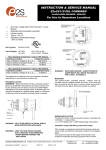
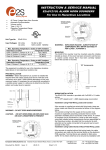
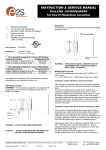
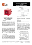
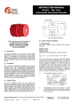
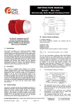
INSTRUCTION & SERVICE MANUAL
E2xCS112-5UL COMBINED
ALARM HORN SOUNDER / BEACON
For Use In Hazardous Locations
Unit Type No.
E2xCS112-5UL
Input Voltages: DC Units
AC Units
G
G
E2xCS112-05UL DC Sounder Section
Tone Switch and Volume
Control Positions
- - +
+
Tone Selection
DIP Switch
S3 S 3 S 2 S2
•
•
•
•
45 Tones 3 stage Alarm Horn Sounder / 5 Joule
Beacon
Automatic Synchronisation (sounder)
Volume control
Type 4 / 4X / 13
Operating Temperature Range
-20ºC to +55ºC
Volume Control
Potentiometer
48V Version
Volume Control
Potentiometer
12V & 24V Versions
7KA1
12V or 24V or 48V
120V or 230V 50/60Hz
Max. Operating Temperature / Code at +55º Ambient
Hazardous Location
Temperature Code
Class I, Division 2, Groups A, B, C, D
T2D (215ºC)
Class II, Division 2, Groups F and G
T6 (85ºC)
Class III, Divisions 1 and 2
T6 (85ºC)
Max. Operating Temperature / Code at +40º Ambient
Hazardous Location
Temperature Code
Class I, Division 2, Groups A, B, C, D
T3 (200ºC)
The equipment is suitable for use in the hazardous locations
listed above or non-hazardous locations only.
PRE-INSTALLATION
WARNING - Before the E2xCS112-5UL combined sounder /
beacon is installed the required tone and output volume must
be set. Note the units are factory set to tone 2 (800/1000Hz
alternating at 2Hz) and maximum output. If necessary the unit
should be connected to a suitable power supply in a safe area
to determine what tone pattern and output level is required.
M4 Hex
Socket Screw
Spring Washer
E2xCS112-05UL AC Sounder Section
Tone Switch and Volume
Control Positions
Tone Selection
DIP Switch
Volume Control
Potentiometer
E E
N N
L L
S3 S2 C
•
WARNING - EXPLOSION HAZARD - SUBSTITUTION OF
COMPONENTS MAY IMPAIR SUITABILITY
FOR CLASS I, II DIVISION 2.
MOUNTING
The E2xCS112-5UL combined sounder / beacon must be
mounted using the rotating bracket as shown. If the cover has
been removed to set the tone or volume control ensure that it
has been correctly replace before the sounder is mounted.
18° Increments
Release nut to rotate
bracket.
WARNING – NOT TO BE USED AS A VISUAL PUBLIC
MODE NOTIFICATION APPLIANCE
WIRING INSTALLATION
The E2xCS112-5UL combined sounder /beacon has one ½
NPT cable entry, the blanking plug adjacent to the cable entry is
permanently fixed and must not be removed. The combined unit
is pre-wired with flying leads which are colour coded and should
be connected as shown in the diagram below.
WARNING – HIGH VOLTAGE SHOCK HAZARD.
WAIT 5 MINUTES AFTER REMOVING
POWER BEFORE OPENING THE
ENCLOSURE
The conduit running from the supply to the combined unit must
include an equipment grounding conductor that is at earth
potential to facilitate ground connection of the device. A number
of combined units can be connected in a chain to the same
supply using field installed wiring compartments that are
Flat Washer
__________________________________________________________________________________________________________________
European Safety Systems Ltd. Impress House, Mansell Road, Acton, London W3 7QH
[email protected]
Tel: +44 (0)20 8743 8880
www.e2s.com
Fax: +44 (0)20 8740 4200
Document No. IS4209 Issue: G
19-06-07
Sheet 1 of 3
appropriate for the hazardous location, provided that the
conductor at earth potential can be readily connected to the
ground lead on each combined unit in the chain.
WARNING - ALL ELECTRICAL WIRING MUST BE
INSTALLED IN ACCORDANCE TO THE
NATIONAL ELECTRICAL CODE
AC Sounder Section
Black
(S)
Live
White (S)
Neutral
Green/Yellow (S) Ground
Violet (S)
Orange (S)
Yellow (S)
L
N
C
S2 S3
L N
It is important that a suitable power supply is used to run the
combined units. The power supply selected must have the
necessary capacity to provide the input current to all of the units
connected to the system.
Sounder Section
C
S2
S3
AC Beacon Section
Black
(B)
Live
White (B)
Neutral
Green/Yellow (B) Ground
L N
POWER SUPPLY SELECTION
Unit Type
Input
Voltage
Input @ 1kHz
Max.
Current
I/P Volts
E2xCS112-5UL
E2xCS112-5UL
E2xCS112-5UL
E2xCS112-5UL
24V DC
48V DC
230V 50/60Hz AC
120V 50/60Hz AC
284mA
146mA
54mA
104mA
Unit Type
Input
Voltage
Input
Current
E2xCS112-5UL
E2xCS112-5UL
E2xCS112-5UL
E2xCS112-5UL
24V DC
48V DC
230V 50/60Hz AC
120V 50/60Hz AC
275mA
145mA
30mA
80mA
30V
58V
253V
132V
Beacon Section
L N
C
S2 S3
L N
L N
C
S2 S3
L N
Sounder
Max.
I/P Volts
30V
58V
253V
132V
C
TONE SELECTION
Stage 2
Stage 3
L
N
Beacon
NOTE if the second and third stage wires are not used they must be
individually insulated to ensure that cannot make contact to any other wires.
DC Sounder Section
Red
(S)
Positive
Black
(S)
Negative
Orange (S)
S2
Yellow (S)
S3
Green/Yellow (S) Ground
The operation of the second and third stages is different for DC
and AC units.
DC Units Second and Third Stage Tone Selection
To activate the second stage, remotely switch the S2 orange
wire to the negative supply. To activate the third stage,
remotely switch the S3 orange wire to the negative supply.
NOTE the DC power supply to the Red (S) and Black (S) wires
must be maintained for 2nd and 3rd stages.
DC Beacon Section
Red
(B)
Positive
Black
(B)
Negative
Green/Yellow (B) Ground
+-
+
-
S2 S3
+-
The E2xCS112-5UL sounder section has 45 different tones that
can be selected for the first stage alarm. The sounder can then
be switched to sound second and third stage alarm tones. The
tones are selected by operation of a DIP switch on the pcb in
the sounder section for both DC and AC units. The tone table
shows the switch positions for the 45 tones and which tones are
available for the second and third stages. To operate the
sounder on stage one simply connect the supply voltage to the
flying leads Red (S) and Black (S) for DC units, Black (S), White
(S) and Green/Yellow for AC units.
+-
S2 S3
+-
+-
S2 S3
+-
Sounder
AC Units Second and Third Stage Tone Selection
To select the second and third stages on the E2xCS112-5UL
AC sounder the Common (C) Violet wire must be remotely
connected to the S2 orange wire for the second stage and to
the S3 yellow wire for third stage. NOTE the AC power supply to
the Black (S) and White (S) wires must be maintained for 2nd
rd
and 3 stages.
Stage 2
Stage 3
+
Beacon
NOTE if the second and third stage wires are not used they must be
individually insulated to ensure that cannot make contact to any other wires.
VOLUME CONTROL
The volume on the E2xCS112-5UL sounder can be set using
the volume control (see figures 2 and 3). For maximum output
level the potentiometer should be set to the fully clockwise
position.
WARNING – HIGH VOLUME MAY CAUSE HARM TO
PERSONNEL IN CLOSE PROXIMITY
__________________________________________________________________________________________________________________
European Safety Systems Ltd. Impress House, Mansell Road, Acton, London W3 7QH
[email protected]
Tel: +44 (0)20 8743 8880
www.e2s.com
Fax: +44 (0)20 8740 4200
Document No. IS4209 Issue: G
19-06-07
Sheet 2 of 3
TONE SELECTION TABLE
Tone 5
4
5
6
7
8
1
0
1
0
1
0
0
0
0
0
Tone 6
Tone 3
Tone 7
Tone 10
Tone 2
Tone 5
Tone 20
Tone 5
Tone 5
Tone 5
9
10
11
12
13
14
15
16
0 0 0 1 0 0
Tone 15
Tone 2
800Hz Continuous
660Hz 150mS on, 150mS off Intermittent
1
0
1
0
1
0
1
0
0
0
0
0
0
0
Tone 7
Tone 2
Tone 4
Tone 15
Tone 4
Tone 2
Tone 18
Tone 5
Tone 5
Tone 5
Tone 5
Tone 5
Tone 5
Tone 5
17
544Hz (100mS)/440 Hz (400m/S)
- NF S 32-001
660Hz 1.8 sec on, 1.8 sec off Intermittent
18
0 0 0 0 1 0
Tone 2
Tone 27
1 0 0 0 1 0
Tone 2
Tone 5
19
20
21
22
23
24
25
26
27
28
29
30
31
32
33
0 1 0 0 1 0
Tone 2
Tone 5
1
0
1
0
1
0
1
0
1
0
1
0
1
0
0
0
0
0
0
0
0
0
0
0
0
0
0
1
Tone 2
Tone 2
Tone 2
Tone 6
Tone 29
Tone 29
Tone 2
Tone 26
Tone 2
Tone 7
Tone 2
Tone 26
Tone 26
Tone 2
Tone 5
Tone 5
Tone 5
Tone 5
Tone 5
Tone 5
Tone 15
Tone 5
Tone 5
Tone 5
Tone 5
Tone 5
Tone 15
Tone 5
800/1000Hz @ 1Hz Sweeping
2400Hz Continuous
2400/2900Hz @ 7Hz Sweeping
2400/2900Hz @ 1Hz Sweeping
500/1200/500Hz @ 0.3Hz Sweeping
1200/500Hz @ 1Hz - DIN
PFEER P.T.A.P.
2400/2900Hz @ 2Hz Alternating
1000Hz @ 1Hz Intermittent
800/1000Hz @ 0.875Hz Alternating
2400Hz @ 1Hz Intermittent
800Hz 0.25 sec on, 1 sec off Intermittent
1.4KHz - 1.6KHz 1s, 1.6KHz - 1.4
KHz 0.5s - NFC48-265
660Hz Continuous
554Hz/440Hz @ 1Hz Alternating
544Hz @ 0.875 sec Intermittent
800Hz @ 2Hz Intermittent
800/1000Hz @ 50Hz Sweeping
2400/2900Hz @ 50Hz Sweeping
Bell
554Hz Continuous
440Hz Continuous
800/1000Hz @ 7Hz Sweeping
300Hz Continuous
660/1200Hz @ 1Hz Sweeping
Two tone chime
745Hz @ 1Hz Intermittent
1
0
0
1
1
0
1
1
0
0
1
1
1
0
0
1
1
0
0
1
1
0
0
1
1
0
0
1
1
1
1
0
0
0
1
1
1
1
0
1
1
1
1
0
0
0
0
1
1
1
1
0
0
0
0
0
0
1
1
1
1
1
1
1
0
0
0
0
0
1
1
1
1
1
1
1
1
0
0
0
0
0
0
0
0
0
0
0
0
0
1
1
1
1
1
1
1
1
1
1
1
1
1
0
34
1000 & 2000Hz @ 0.5 sec
Aletrnating - Signapore
1 0 0 0 0 1
Tone 38
Tone 45
35
420Hz @ 0.625 Sec Australian Alert
0 1 0 0 0 1
Tone 36
Tone 5
36
500-1200Hz 3.75 sec /0.25 sec
Australian Evac.
1 1 0 0 0 1
Tone 35
Tone 5
37
38
39
1000Hz Continuous - PFEER Toxic Gas
2000Hz Continuous
800Hz 0.25 sec on, 1 sec off Intermittent
0 0 1 0 0 1
1 0 1 0 0 1
0 1 1 0 0 1
Tone 9
Tone 34
Tone 23
Tone 45
Tone 45
Tone 17
40
544Hz (100mS)/440Hz (400mS)
- NF S 32-001
1 1 1 0 0 1
Tone 31
Tone 27
41
42
43
44
Motor Siren - slow rise to 1200Hz
Motor Siren - slow rise to 800Hz
1200Hz Continuous
Motor Siren - slow rise to 2400Hz
0
1
0
1
1
1
1
1
Tone 2
Tone 2
Tone 2
Tone 2
Tone 5
Tone 5
Tone 5
Tone 5
45
1KHz 1s on, 1s off Intermittent
- PFEER Gen. Alarm
0 0 1 1 0 1
Tone 38
Tone 34
0
0
0
0
1
1
1
1
0
0
0
0
E2xCS112-5UL DC
Sounder Section
End of Line Resistor
End of Line Resistor
E2xCS112-5UL DC
Beacon Section
End of Line Resistor
G
0
0
1
1
The resistor must be connected directly across the +ve and –ve
terminals as shown in the following drawings. Whilst keeping its
leads as short as possible, a spacing of at least 1/16 inch
(1.58mm) must be provided through air and over surfaces
between uninsulated live parts.
+ G G
Tone 2
500/1200Hz @ 0.3Hz sec
Slow Whoop
Minimum wattage 0.5W
Minimum wattage 2.0W
- - +
0 1 0 0 0 0
3
Minimum Resistance 15k ohms
Minimum Resistance 3k9 ohms
S3 S3 S2 S2
Tone 5
Tone 5
-
Stage 3
Tone 2
Tone 17
340Hz Continuous
800/1000Hz @ 0.25 sec Alternating
-
Stage 2
1
2
+ +
Switch
1 2 3 4 5 6
0 0 0 0 0 0
1 0 0 0 0 0
Frequency Description
G
Stage 1
48V DC Sounders
SWITCH POSITION EXPLANATION
1 = Switch in the ON position.
0 = Switch in the OFF position..
End of Line Resistor
END OF LINE MONITORING
On E2xCS112-5UL DC units, dc reverse line monitoring can
be used on both the sounder section and the beacon section if
required. All DC combined units have a blocking diode fitted in
the supply input lines to both the sounder and the beacon. An
end of line monitoring resistor can be connected across the
+ve and –ve terminals. If an end of line resistor is used it must
have the following values:24V DC Sounders
Minimum Resistance 3k9 ohms
Minimum Resistance 1k ohms
Minimum wattage 0.5W
Minimum wattage 2.0W
__________________________________________________________________________________________________________________
European Safety Systems Ltd. Impress House, Mansell Road, Acton, London W3 7QH
[email protected]
Tel: +44 (0)20 8743 8880
www.e2s.com
Fax: +44 (0)20 8740 4200
Document No. IS4209 Issue: G
19-06-07
Sheet 3 of 3