1
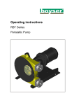
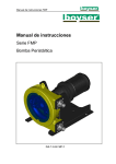
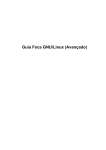
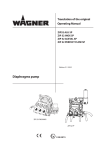
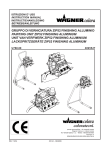
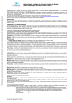
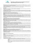
Operating instructions
FMP Series
Peristaltic Pump
FMP Instruction Manual
Table of contents
1. Introduction ...................................................................................... 3
2. Safety and Responsibility .................................................................. 5
3. Functional description ....................................................................... 9
4. Transport and Storage .................................................................... 11
5. Assembly and Installation ............................................................... 12
6. Commissioning................................................................................ 18
7. Maintenance, repair, malfunctions, disposal and spare parts ......... 19
8. Spare parts ..................................................................................... 25
9. Declaration of Conformity ............................................................... 43
10. Guarantee....................................................................................... 44
2
FMP Instruction Manual
1. Introduction
This manual forms an integral part of the pump and must accompany it until its
demolition. The series FMP peristaltic pump is a machine destined to work in
industrial areas and as such the instruction manual must form part of the
legislative dispositions and the applicable technical standards and does not
substitute any installation standard or eventual additional standard.
1.1
Explanation of the safety information
The instructions of this manual, whose inobservance is
determined as a failure to meet safety standards, are
identified by this symbol
The instructions of this manual, whose inobservance
compromises electrical safety
The instructions of this manual, whose inobservance
compromises the correct working of the pump, are
identified with this symbol.
1.2
Users’ qualifications
Pumps are machines that due to their functioning under pressure and moving
parts can present dangers.
- Improper use
- Removing the protections and/or disconnecting the protection device
3
FMP Instruction Manual
- The lack of inspections and maintenance
They can cause serious damage or injury.
The person in charge of safety should therefore guarantee that the pump is
transported, installed, put in service, used, maintained and repaired by qualified
personnel who should therefore possess:
- Specific training and sufficient experience.
- Knowledge of the technical standards and applicable laws.
- Knowledge of the general national and local safety standards and also
of installation.
Any work carried out on the electrical part of the pump should be authorized by
the person responsible for safety. Given that the pump is destined to form part
of an installation, it is the responsibility of whoever supervises the installation to
guarantee absolute safety, adopting the necessary measures of additional
protection.
4
FMP Instruction Manual
2. Safety and Responsibility
2.1
General safety information
Live parts
Possible consequence: Fatal or very serious injuries.
-
-
Measure: The device must be disconnected from the power
supply before it is opened
Isolate damaged faulty or manipulated devices from the mains in
order to de-energise.
Emergency stop switch
Possible consequence: Fatal or very serious injuries.
An emergency stop switch is to be connected for the entire plant. This
should enable the entire plant to be shut down in the event of an
emergency in such a way that the overall plant can be brought into a
safe condition.
Unauthorized access
Possible consequence: Fatal or very serious injuries.
- Measure: Ensure that there can be no unauthorized access to the
unit.
Hazardous media/contamination of persons and equipment
Possible consequence: Fatal or very serious injuries material damage.
-
-
Ensure that the pump hoses are resistant against the media being
conveyed
Always observe the safety data sheets for the media to be
conveyed. The system operator must ensure that these safety
data sheets are available and that they are kept up-to-date.
The safety data sheets for the media being conveyed are always
decisive for initiating countermeasures in the event of leakage to
the media being conveyed.
5
FMP Instruction Manual
Observe the general restrictions in relation to viscosity limits,
chemical resistance and density.
Always switch the pump off before exchanging the pump hose
-
Correct and proper use
Possible consequence: Fatal or very serious injuries.
-
-
-
-
The unit is not intended to convey or regulate gases or solid
media
Do not exceed the rated pressure, speed or temperature for the
pump
The unit may only be used in accordance with the technical data
and specifications provided in these operating instructions and in
the operating instructions for the individual components
The system is not designed for use in areas of risk from explosion
Only switch the pump on if it has been properly fastened to the
floor
Only switch the pump on if it the front cover has been attached.
Do not carry out any maintenance operations or dismantle the
pump without first making sure that the pipes are not under
pressure and are empty or isolated.
In the case of the hose becoming stuck during extraction or fitting
it is necessary to reverse the direction of the pump, relubricate,
and then repeat the operation.
As the peristaltic pump is volumetric and its functioning is positive
displacement, it is necessary to prevent a possible overload of
pressure, due to for example, the accidental closure of a valve.
For this reason it is advisable to fit a safety device such as: a
safety valve, pressure limiter, etc.
Operational lifetime of the pump hoses
Possible consequence: Fatal or very serious injuries.
The operational lifetime of the pump hoses cannot be precisely
specified. For this reason, the possibility of fracture and consequential
leakage of liquids must be accounted for. If the hose rupture alarm
(optional) is fitted, then the pump can be stopped and / or an electrical
valve can be actuated.
6
FMP Instruction Manual
In addition, as the hose has an indeterminate life and due to the
possibility of its breakage or deterioration, the user is responsible for the
prevention of a possible (although most unlikely) incorporation of
particles form the hose into the product being pumped. This can be
achieved e.g. by means of filtration, a hose rupture alarm or other means
suitable for the respective process
CIP cleaning
In the event of CIP cleaning, it is necessary to obtain information from
the manufacturer about correct installation of the pump (a special
installation is required) as well as regarding the compatibility of the
cleaning agents with the pump hoses and the hydraulic connections.
Cleaning should be undertaken at the recommended maximum
temperature.
Direction of rotation/flow direction
Possible consequence: Material damage right through to destruction of
the unit.
-
The pump's direction of rotation in relation to the desired flow
direction must be checked prior to every start.
Disconnect the pump from the mains
Possible consequence: Personal injury.
You may only carry out work on the pump after it has previously been
switched off and disconnected from the mains.
7
FMP Instruction Manual
Environmental influences
Possible consequence: Material damage right through to destruction of
the unit.
-
The device is not suitable for outdoor operation
Take suitable measures to protect the device from environmental
influences such as:
– UV rays
– Moisture
– Frost, etc.
8
FMP Instruction Manual
3. Functional description
The FMP Series is a displacement pump. The feed chemical is conveyed by the
rotor squeezing the hose in the direction of flow. No valves are needed for this.
This ensures gentle handling of the metered media.
The FMP Series has been designed for safe and uncomplicated operation, as
well as straightforward maintenance.
The FMP Series can be used for many different media. However, this pump
type is often the optimal solution for abrasive, shear-sensitive and viscose
media.
Typical areas of use include processes where only a low discharge pressure is
required (max. 8 Bar).
3.1
Construction
Main modules:
-
Drive Unit
Housing
Base frame
The pump housing is closed off with a screwed front cover in order to avoid the
risk of injury.
The motor serves to drive the rotor. Two rollers at the ends of the rotor serve to
press the pump hose against the pump housing.
The rotary movement of the rotors alternately press and relax the rollers in
relation to the pump hose. This serves to suck the media and convey it into the
metering line.
9
FMP Instruction Manual
Fig. 1: Diagram of functional principle
1 Housing
3 Rollers
2 Rotor
4 Hose
10
FMP Instruction Manual
4. Transport and Storage
4.1
Transport
-
The pump is protected by a cardboard packaging.
-
The packaging materials are recyclable.
4.2
Storage
-
The pump should be in a resting position. (The hose should not be
compressed).
-
Avoid areas open to harsh weather or excessive humidity.
-
For storage periods of longer than 60 days, protect the coupling surfaces
(clamps, reducers, motors) with adequate anti-oxidant products.
-
4.3
Spare hoses should be stored in a dry place away from direct light.
Elevation
Models FMP-30, FMP-40, FMP-50
Models FMP-60, FMP-70, FMP-70D
- To elevate the pump use the eye
bolt.
- To elevate the pump, it’s
necessary to use elevation belts.
11
FMP Instruction Manual
5. Assembly and Installation
5.1
Ambient conditions
Assembly is to be carried out in the following order. If the pump has to be
installed outdoors, then it is to be equipped with protection against sunlight and
weather influences. When positioning the pump, ensure that sufficient room for
access is provided for all types of maintenance work.
Limit values for hose temperature and pressure
Material Hose
Min. Temp.
(ºC) Feed
chemical
Max. Temp
(ºC) Feed
chemical
Max.
Pressure
(Bar)
Min. Temp (ºC)
Environment
NR
- 20
80*
- 40
8
NBR
- 10
80*
- 40
8
EPDM
- 10
80*
- 40
8
NR-A
- 10
80*
- 40
8
NBR-A
- 10
80*
- 40
8
120*
- 40
2
NORPRENE1 - 10
1
Only available for FMP-40
* At max. Tª, the life of hose is drastically reduced. Please contact with Boyser or
authorized distributor for high Tª application.
5.2
Correct installation of the pump
5.2.1 Suction side
The pump is to be positioned as near as possible to the liquid container, so that
the suction side is kept as short and straight as possible. The suction line must
be absolutely airtight and made of a suitable material, so that it is not squeezed
together under vacuum. The diameter must correspond to the rated diameter of
the pump hose. A larger diameter is recommended in the event of viscose
liquids. The pump is self-priming and does not require an admission valve. The
pump is reversible and the suction connection can therefore comprise of one of
12
FMP Instruction Manual
two options. Normally the option is selected which is best suited to the physical
conditions of the installation. It is recommended to use a flexible transition
between two fixed pipes and the hydraulic connection of the pump, in order to
avoid the transmission of vibrations.
5.2.2 Discharge side
The discharge line is to be kept as straight and short as possible, in order to
avoid performance reduction. The diameter must correspond to the rated
diameter of the pump hose. A larger diameter is recommended in the event of
viscose liquids. It is recommended to use a flexible transition between two fixed
pipes and the hydraulic connection of the pump, in order to avoid the
transmission of vibrations.
5.3
Adjusting the roller pressure
The peristaltic pump is equipped with shims, in order to adjust the precise
pressure distance to the roller (dependent on speed and operating pressure).
Fig 2: 1- Roller / 2- Shims
13
FMP Instruction Manual
Fig. 3: Squeezing the hose
1. Hose in normal shape
2. Insufficient squeezing (back flowing media in the cavity will destroy the hose within a
short period of time)
3. Perfect squeezing
4. Excessive squeezing (increased wear and tear to pump and hose)
The shims are fitted in the factory. You can adapt the number of shims to the
actual operating conditions according to the following table.
14
FMP Instruction Manual
5.3.1 FMP-30 Model (Number of shims of 0,5 mm thickness):
a) NR, NBR, EPDM, HYPALON, NR-A and NBR-A:
1/min
0-19
20-39
40-59
60-79
0,5
2
2
1
1
2,0
2
2
2
2
Bar
4,0*
3
2
2
2
6,0
3
3
3
2
8,0
4
3
3
-*Factoring default setting if working pressure is not informed
80-99
1
2
2
---
5.3.2 FMP-40 Model (Number of shims of 1 mm thickness):
a) NR, NBR, EPDM, HYPALON, NR-A and NBR-A:
1/min
0-19
20-39
40-59
60-79
0,5
4
4
4
4
2,0
5
4
4
4
Bar
4,0*
5
5
5
4
6,0
6
5
5
-8,0
6
6
--*Factoring default setting if working pressure is not informed
80-99
3
4
4
---
b) Norprene:
1/min
0-19
20-39
40-59
60-79
0,5
14
14
14
14
Bar
2,0*
14
14
14
14
*Factoring default setting if working pressure is not informed
80-99
14
14
15
FMP Instruction Manual
5.3.3 FMP-50 Model (Number of shims of 1 mm thickness):
a) NR, NBR, EPDM, HYPALON, NR-A and NBR-A:
1/min
0-19
20-39
40-59
60-79
0,5
1
1
1
0
2,0
2
1
1
1
Bar
4,0*
2
2
2
2
6,0
3
3
3
3
8,0
4
3
--*Factoring default setting if working pressure is not informed
80-99
0
1
2
---
5.3.4 FMP-60 Model (Number of shims of 1 mm thickness):
a) NR, NBR, EPDM, HYPALON, NR-A and NBR-A:
1/min
0-19
20-39
40-59
60-79
0,5
6
5
5
5
2,0
6
6
6
6
Bar
4,0*
6
6
6
6
6,0
7
6
6
6
8,0
7
7
7
7
*Factoring default setting if working pressure is not informed
80-99
5
5
6
6
--
5.3.5 FMP-70 Model (Number of shims of 1 mm thickness):
a) NR, NBR, EPDM, HYPALON, NR-A and NBR-A:
1/min
0-19
20-39
40-59
60-79
0,5
1
1
0
0
2,0
1
1
1
0
Bar
4,0*
2
2
2
1
6,0
3
3
2
-8,0
4
3
3
-*Factoring default setting if working pressure is not informed
80-99
0
0
1
---
16
FMP Instruction Manual
5.3.6 FMP-70D Model (Number of shims of 1 mm thickness):
Each of the two pump bodies is fitted with the following configuration:
a) NR, NBR, EPDM, HYPALON, NR-A and NBR-A:
1/min
0-19
20-39
40-59
60-79
0,5
1
1
0
0
Bar
2,0
1
1
1
0
3,0*
2
2
2
1
*Factoring default setting if working pressure is not informed
80-99
0
0
1
17
FMP Instruction Manual
6. Commissioning
6.1
Testing prior to commissioning the pump
The following tests are to be carried out:
-
Ensure that the pump has not been damaged during transportation or
storage. Immediately report any damage to the supplier.
-
Check that the mains voltage is suitable for the motor.
-
Ensure that the hose is suitable for the fluid to be conveyed and that it is
not damaged.
-
Make sure that the temperature of the liquid does not exceed the
recommended temperature range.
-
Only switch the pump on if it the front cover has been properly attached.
-
Check that the rollers are correctly fitted and fastened.
- Check that the drive pump and the inner of the rollers are correctly
greased. The specially formulated grease can be obtained from
BOMBAS BOYSER, S.L. or from the authorized distributor.
-
Check that the thermal overload protection (not included in the delivery
scope) corresponds to the value specified on the motor type plate.
-
Check whether the direction of rotation is correctly adjusted.
-
Check that the optional electrical components are connected and are
working properly.
-
Install a manometer in the pressure line if the back-pressure value is
unknown.
-
Check the operating instructions in order to ensure that the flow values,
pressures and power consumption of the motor do not exceed the rated
values.
-
Install a pressure relief valve in the pressure line in order to protect the
pump in the event that a valve is unintentionally closed off or the line is
blocked in another way.
18
FMP Instruction Manual
7. Maintenance, repair, malfunctions, disposal and spare parts
7.1
Lubrication:
-
Check that the rollers and the hose are sufficiently lubricated
o Check every 300 operating hours
-
Gear reducers
o FMP-30, FMP-40 and FMP-50: The lubrication is permanent. Is
not necessary any servicing.
o FMP-60, FMP-70 and FMP-70D: Exchange the oil at regular
intervals in accordance with the gear reducer maintenance
manual.
7.2
Exchanging the pump hoses
7.2.1 Exchanging the pump hoses – dismantling
7.2.1.1 Models FMP-30, FMP-40, FMP-50, FMP-70 and FMP-70D
1. Close off all valves, in order to prevent leakage of the feed chemical
2. Dismantle the pipes from both discharge and suction sides
3. Remove the front cover
4. Remove a roller (the roller that is not touching the pump hose)
5. Mount the front cover
6. Turn the rotor with the help of the motor so that the remaining roller is not
pressing against the pump hose
7. Dismount the front cover
8. Remove the press flange and connections from the pump housing
9. Remove the press rings
10 Remove the pump hose to be exchanged
19
FMP Instruction Manual
7.2.1.2 Model FMP-60:
1. Close off all valves, in order to prevent leakage of the feed chemical
2. Dismantle the pipes from both discharge and suction sides
3. Remove the front cover
4. Remove a roller (the roller that is not touching the pump hose)
5. Mount the front cover
6. Turn the rotor with the help of the motor so that the remaining roller is not
pressing against the pump hose
7. Dismount the front cover
8. Remove the connections
9. Remove the press flange from the pump housing
10 Remove the pump hose to be exchanged
11 Dismantle the inserts from both pump hose ends
7.2.2 Exchanging the pump hoses- installation
7.2.2.1 Models FMP-30, FMP-40, FMP-50, FMP-70 and FMP-70D
1. Clean the interior surfaces of the pump housing
2. Lubricate the internal surfaces of the pump housing at the contact
surfaces to the pump hose with original silicon grease
3. Check the rollers. Ensure that the roller surfaces are not damaged
4. Lay the pump hose into the pump housing
5. Lay the press rings. Between the end of the hose and the press ring, it
has to be a distance of 3-7 mm.
20
FMP Instruction Manual
Fig.4: Required distance between the end of
the hose and the press ring.
6. Fasten the press flange and the connections to the pump casing,
tightening progressive the bolts in clock wise (1, 2, 3, 4, 1, 2, 3, 4,
etc…), until the flange becomes totally tighten.
Fig.5: Way to proceed with the screws tightening
21
FMP Instruction Manual
7. Mount the front cover
8. Turn the rotor with the help of the motor so that the remaining roller
presses against the pump hose
9. Dismount the front cover
10. Re-attach the second roller with shims back onto the rotor
11. Lubricate the pump hose and the rollers
12. Attach the front cover to the pump housing
13. Mount the pipes from both discharge and suction sides
14. Open all of the valves
7.2.2.2 Model FMP-60:
1. Clean the interior surfaces of the pump housing
2. Lubricate the internal surfaces of the pump housing at the contact
surfaces to the pump hose with original silicon grease
3. Check the rollers. Ensure that the roller surfaces are not damaged
4. Lay the pump hose into the pump housing
5. Attach the inserts at both hose ends with the help of the press flange
6. Fasten the two parts of press flanges us the base
7. Fasten the press flange to the pump casing
8. Fasten the connections to the press flange
9. Mount the front cover
10. Turn the rotor with the help of the motor so that the remaining roller
presses against the pump hose
11. Dismount the front cover
12. Re-attach the second roller with shims back onto the rotor
13. Lubricate the pump hose and the rollers
14. Attach the front cover to the pump housing
15. Mount the pipes from both discharge and suction sides
16. Open all of the valves
22
FMP Instruction Manual
7.3
Troubleshooting
Problem
Increased pump
temperature
Possible cause
Solution
Pump hose has no lubricant
Lubricate pump hose
Increased product temperature
Reduce product temperature
Insufficient or poor suction conditions
Check suction line for blockages
Pump speed too high
Reduce pump speed
Valves on discharge and or suction side
completely or partially closed
uuuuuuuuuuuuuuuuuuuuuuu
Pump hose insufficiently compressed
partially closed
Pump hose rupture (the product leaks
out into the housing)
Open valves
Check number of shims
Exchange pump hose
Partial blockage of the suction line
Clean pipe
Insufficient product quantity in storage
container
Fill storage container or exchange pump
Insufficient diameter on the suction side
Increase the diameter on the suctions
side, as far as possible
Suction line too long
Shorten the suction line, as far as possible
High viscosity of medium
Reduce viscosity, as far as possible
Reduced flow or
pressure
Air introduction in the suction
connections
Reduced flow or
pressure
High pulsation on suction
Check connections and accessories for air
tightness
Tighten connections and accessories
Mount antipulsation equipment
Reconsider application (speed, etc)
Reduced flow or
pressure
Vibrations on
pumps and
pipelines
The pipes are not correctly fastened
Fasten pipes correctly (e.g. wall brackets)
Pump speed too high
Reduce pump speed
Insufficient nominal width of the pipes
Increase nominal width
Pump base plate loose
Fasten base plate
Pulsation dampers insufficient or
missing
Install pulsation dampers on suction and /
or discharge side.
23
FMP Instruction Manual
Short
operational
lifetime of the
hoses
Pump hose
pulled into the
pump housing
The pump does
not start up
Chemical exposure
Check the compatibility of the hose with
the liquid being conveyed, the cleaning
fluid and the lubricant
High pump speed
Reduce pump speed
High conveying temperature
Reduce product temperature
High operating pressure
Reduce operating pressure
Pump cavitation
Check the suction conditions
Abnormal elevation of temperature
Check rollers shaft mounting
Unsuitable lubricant
Use lubricant BOYSER
Insufficient quantity of grease
Top up lubricant
High inlet pressure (> 3 bar)
Reduce inlet pressure
Pump hose filled with deposits
Clean or replace the pump hose
Holder (press flange) insufficiently
tightened
Re-tighten holder (press flange)
Insufficient grease
Top lubricant
Insufficient motor performance
Check motor and replace if necessary
Insufficient output from frequency
converter
The frequency converter must match the
motor
Check voltage. Start occurs at minimum
10 Hz
Check if the suction or discharge side is
blocked. Rectify blockage
Blockage in the pump
Blockage in the pump
24
FMP Instruction Manual
8. Spare parts
8.1
Spare parts exploded FMP-30 Model
25
FMP Instruction Manual
Pos.
1
2
3
4
5
6
7
8
9
10
11
12
13
14
15
16
17
18
19
20
21
22
24
25
26
Description
Pump body
Ball bearing box
Rotor shaft
Rotor
Roller support
Shim
Shaft screw
Roller shaft
Roller
Metallic cover
Polycarbonate cover
Press flange
Press ring
Connection SS 1 1/4” BSP
Connection SS 1 1/4” NPT
Connection DIN 11851 NW32
Connection TRI-CLAMP
Connection flange DIN DN32 INOX
Connection flange ANSI DN32 INOX
Connection polypropylene 1 1/4” BSP
Peristaltic hose NR
Peristaltic hose NR-A
Peristaltic hose NBR
Peristaltic hose NBR-A
Peristaltic hose EPDM
Shaft cap
Base left
Base left S.S
Base right
Base right S.S
Base middle
Base middle S.S
Stud
Driver
Ball bearings
Ball bearings roller
Ring for shaft
Lip seal box
Quantity
1
1
1
1
2
2
2
2
1
1
2
2
2
2
2
2
2
2
2
1
1
1
1
1
1
1
1
1
2
2
1
2
4
1
1
Reference
107.00.01
107.00.03
107.00.04
107.00.05
107.00.06
107.00.07
107.00.08
107.00.09
107.00.11
107.00.13
107.00.14
107.00.15
100.00.05
107.00.17
107.00.34
107.00.35
107.00.36
107.00.37
107.00.38
107.00.39
107.00.18
107.00.19
107.00.20
107.00.21
107.00.22
110.00.23
100.01.24
100.01.34
100.01.25
100.01.35
100.01.26
100.01.36
102.00.14
100.01.28
107.00.30
100.01.31
100.01.32
26
FMP Instruction Manual
Pos.
27
28
29
Description
Lip seal roller
Eye bolt
Drain plug FMP
Quantity
4
1
3
Reference
107.00.33
106.00.40
107.00.41
27
FMP Instruction Manual
8.2 Spare parts exploded FMP-40 Model
28
FMP Instruction Manual
Pos.
1
2
3
4
5
6
7
8
9
10
11
12
13
14
15
16
17
Description
Pump body
Ball bearing box
Rotor shaft
Rotor
Roller support
Shim 1mm
Shim 4mm
Shaft screw
Roller shaft
Roller
Metallic cover
Metallic cover vacuum equipment
Polycarbonate cover
Press flange
Press ring
Press ring for NORPRENE hose
Connection SS 1 1/2” BSP
Connection SS 1 1/2” NPT
Connection DIN 11851 NW40
Connection TRI-CLAMP
Connection flange DIN DN40 INOX
Connection flange ANSI DN40 INOX
Connection Polypropylene 1 1/2” BSP
Connection PVDF 1 1/2” BSP
Connection Polypropylene 1 1/2” NPT
Connection SMS-38
Peristaltic hose NR
Peristaltic hose NR-A
Peristaltic hose NBR
Peristaltic hose NBR-A
Peristaltic hose EPDM
Peristaltic hose HYPALON
Peristaltic hose NORPRENE
Shaft cap
Base left
Base left S.S
Base left trolley steel
Base left trolley S.S
Quantity
1
1
1
1
2
2
2
2
1
1
1
2
2
2
2
2
2
2
2
2
2
2
2
2
1
1
1
1
1
1
1
1
1
1
1
1
Reference
106.00.01
106.00.03
106.00.04
106.00.05
106.00.06
106.00.07
106.00.49
106.00.08
106.00.09
106.00.11
106.00.13
106.00.43
106.00.14
106.00.15
104.00.05
106.00.51
106.00.17
106.00.34
106.00.35
106.00.36
106.00.37
106.00.38
106.00.39
106.00.41
106.00.47
106.00.42
106.00.18
106.00.19
106.00.20
106.00.21
106.00.22
106.00.48
106.00.50
106.00.23
106.00.24
106.00.44
106.00.52
106.00.54
29
FMP Instruction Manual
Pos.
18
19
20
21
22
23
24
25
26
27
28
29
Description
Base right
Base right S.S
Base right trolley steel
Base right trolley S.S
Base middle
Base middle S.S
Stud
Driver
Ball bearing anterior
Ball bearing posterior
Ball bearing roller
Ring for shaft
Lip seal box
Lip seal roller
Eye bolt
Drain plug FMP
Quantity
1
1
1
1
2
2
2
1
1
1
4
1
1
4
1
3
Reference
106.00.25
106.00.45
106.00.53
106.00.55
106.00.26
106.00.46
106.00.27
106.00.28
106.00.29
106.00.30
106.00.31
106.00.32
106.00.33
106.00.40
107.00.41
30
FMP Instruction Manual
8.3
Spare parts exploded FMP-50 Model
31
FMP Instruction Manual
Pos.
1
2
3
4
5
6
7
8
9
10
11
12
13
14
15
16
17
18
19
20
21
22
23
Description
Pump body
Ball bearing box
Rotor shaft
Rotor
Roller support
Shim
Shaft screw
Roller shaft
Roller
Metallic cover
Polycarbonate cover
Press flange
Press ring
Connection flange DN50 S.S
Connection ANSI flange DN-50 SS
Connection flange DN50 PP
Connection ANSI flange DN-50 PP
Connection flange DN-50 PVDF
Connection ANSI flange DN-50 PVDF
Connection DIN 11851 NW-50
Connection TRI-CLAMP
Peristaltic hose NR
Peristaltic hose NR-A
Peristaltic hose NBR
Peristaltic hose NBR-A
Peristaltic hose EPDM
Peristaltic hose HYPALON
Shaft cap
Base left
Base left S.S
Base right
Base right S.S
Base middle
Base middle S.S
Stud
Driver
Ball bearing anterior
Ball bearing posterior
Quantity
1
1
1
1
2
2
2
2
1
1
2
2
2
2
2
2
2
2
2
2
1
1
1
1
1
1
1
1
1
1
1
2
2
2
1
1
1
Reference
108.00.01
108.00.02
108.00.03
108.00.04
108.00.05
108.00.06
108.00.07
108.00.08
108.00.09
108.00.10
108.00.39
108.00.11
108.00.12
108.00.13
108.00.14
108.00.16
108.00.17
108.00.18
108.00.19
108.00.15
108.00.20
108.00.21
108.00.22
108.00.23
108.00.24
108.00.25
108.00.26
108.00.36
108.00.27
108.00.37
108.00.28
108.00.38
108.00.29
108.00.30
32
FMP Instruction Manual
Pos.
24
25
26
27
28
29
30
31
Description
Ball bearing roller
Ring for shaft
Lip seal box
Lip seal roller
Eye bolt
Drain plug FMP-50
O-Ring front cover
Lateral rotor
Quantity
4
1
1
4
1
3
1
2
Reference
108.00.31
108.00.32
108.00.33
108.00.34
108.00.35
108.00.44
33
FMP Instruction Manual
8.4
Spare parts exploded FMP-60 Model
34
FMP Instruction Manual
Pos.
1
3
4
5
6
7
8
9
10
11
12
13
14
15
16
17
18
19
20
21
22
Description
Pump body
Ball bearing box
Rotor shaft
Rotor
Roller support
Shim 1mm
Shim 7mm
Shim 5mm
Shaft screw
Roller shaft
Separator
Roller
Lateral rotor
O-ring cover
Front cover transparent
Press flange
Insert S.S
Insert Polypropylene
Insert PVDF
Connection flange DIN
Connection flange ANSI
Connection TRI-CLAMP
Connection DIN 11851
Connection flange DIN (Halar)
Connection flange ANSI (Halar)
Peristaltic hose NR
Peristaltic hose NR-A
Peristaltic hose NBR
Peristaltic hose NBR-A
Peristaltic hose EPDM
Peristaltic hose HYPALON
Bearing box cap
Base left
Base left S.S
Base right
Base right S.S
Base middle 100mm
Base middle S.S 100mm
Quantity
1
1
1
1
2
2
2
4
2
2
1
1
2
2
2
2
2
2
2
2
2
2
1
1
1
1
1
1
1
1
1
1
1
1
1
Reference
110.00.01
110.00.03
110.00.04
110.00.05
110.00.06
110.00.07
110.00.55
110.00.56
110.00.08
110.00.09
110.00.10
110.00.11
110.00.12
110.00.13
110.00.14
110.00.15
110.00.16
110.00.46
110.00.47
110.00.17
110.00.41
110.00.42
110.00.43
110.00.44
110.00.45
110.00.18
110.00.19
110.00.20
110.00.21
110.00.22
110.00.54
110.00.23
110.00.37
110.00.48
110.00.38
110.00.49
110.00.39
110.00.50
35
FMP Instruction Manual
Pos.
23
24
25
26
27
28
29
30
31
32
34
35
36
37
38
39
Description
Base middle 60mm
Base middle S.S 60mm
Stud
Driver
Ball bearing anterior
Ball bearing posterior
Roller ball bearing
Elastic Ring for shaft
Bearing box lip seal
Roller lip seal
O-ring connection
O-ring cover
Eye bolt
Nut
Nut
Drain plug FMP
Check valve
Quantity
2
2
2
1
1
1
4
1
1
1
2
1
1
2
2
3
1
Reference
110.00.40
110.00.51
106.00.27
110.00.26
110.00.27
110.00.28
110.00.29
110.00.30
110.00.31
110.00.32
110.00.33
110.00.34
110.00.35
110.00.36
107.00.41
110.00.53
36
FMP Instruction Manual
8.5
Spare parts exploded FMP-70 Model
37
FMP Instruction Manual
Pos.
1
2
3
4
5
6
7
8
9
10
12
13
14
15
16
17
18
19
20
21
22
23
24
Description
Pump body
Ball bearing box
Rotor shaft
Rotor
Roller support
Shim
Shaft screw
Roller shaft
Roller
Front cover
Press flange
Press ring
Connection DIN flange S.S
Connection ANSI flange S.S
Connection DIN 11851 NW-65
Connection DIN flange PP
Connection ANSI flange PP
Connection DIN flange PVDF
Connection ANSI flange PVDF
Connection TRI-CLAMP
Peristaltic hose NR
Peristaltic hose NR-A
Peristaltic hose NBR
Peristaltic hose NBR-A
Peristaltic hose EPDM
Peristaltic hose HYPALON
Shaft cap
Base left
Base left S.S
Base right
Base right S.S
Base middle
Base middle S.S
Stud
Driver
Ball bearing anterior
Ball bearing posterior
Ball bearing roller
Quantity
1
1
1
1
2
2
2
2
1
2
2
2
2
2
2
2
2
2
2
1
1
1
1
1
1
1
1
1
1
2
2
2
1
2
1
4
Reference
112.00.01
111.00.03
111.00.04
112.00.02
112.00.03
112.00.04
112.00.05
112.00.06
112.00.07
112.00.08
112.00.09
112.00.10
112.00.11
112.00.12
112.00.13
112.00.14
112.00.15
112.00.16
112.00.17
112.00.43
112.00.18
112.00.19
112.00.20
112.00.21
112.00.22
112.00.23
111.00.08
112.00.24
112.00.36
112.00.25
112.00.37
112.00.26
112.00.38
112.00.44
111.00.28
111.00.29
112.00.27
38
FMP Instruction Manual
Pos.
25
26
27
28
29
30
31
32
33
34
Description
Ring for shaft
Lip seal box
Lip seal roller
Eye bolt
Drain plug FMP-70
Roller ferrule
Lateral rotor
Inspection window (fixed model)
Inspection window (movil model)
O-ring front cover
Quantity
1
1
4
1
3
2
2
1
1
1
Reference
111.00.30
111.00.31
112.00.28
112.00.29
112.00.30
112.00.31
112.00.32
112.00.33
112.00.34
112.00.35
39
FMP Instruction Manual
8.6
Spare parts exploded FMP-70D Model
40
FMP Instruction Manual
Pos.
1
2
3
4
5
6
7
8
9
10
12
13
14
15
16
17
18
19
20
21
22
23
24
25
26
27
28
29
30
31
Description
Pump body
Ball bearing box
Rotor shaft
Rotor
Roller support
Shim
Shaft screw
Roller shaft
Roller
Front cover
Press flange
Press ring
Connection DIN flange S.S
Connection ANSI flange S.S
Peristaltic hose NR
Peristaltic hose NR-A
Peristaltic hose NBR
Peristaltic hose NBR-A
Peristaltic hose EPDM
Peristaltic hose HYPALON
Shaft cap
Base
Base S.S
Base middle
Base middle S.S
Dual shaft
Stud
Driver
Ball bearing anterior
Ball bearing posterior
Ball bearing roller
Ring for shaft
Lip seal box
Lip seal roller
Eye bolt
Drain plug FMP-70
Roller ferrule
Lateral rotor
Quantity
2
2
2
2
4
4
4
4
2
4
4
4
4
2
2
2
2
2
2
2
1
1
2
2
1
4
1
4
1
4
2
2
8
2
6
4
4
Reference
112.00.01
111.00.03
111.00.04
112.00.02
112.00.03
112.00.04
112.00.05
112.00.06
112.00.07
112.00.08
112.00.09
112.00.10
112.00.11
112.00.12
112.00.18
112.00.19
112.00.20
112.00.21
112.00.22
112.00.23
111.00.08
112.00.48
112.00.53
112.00.49
112.00.54
112.00.46
112.00.44
111.00.28
111.00.29
112.00.27
111.00.30
111.00.31
112.00.28
112.00.29
112.00.30
112.00.31
112.00.32
41
FMP Instruction Manual
Pos.
32
33
34
35
36
37
Description
Inspection window (fixed model)
Inspection window (mobile model)
O-ring front cover
Metallic cover ring
Gear reducer coupling
Collector DIN S.S
Collector ANSI S.S
Quantity
2
2
2
1
2
2
2
Reference
112.00.33
112.00.34
112.00.35
112.00.51
112.00.47
112.00.50
112.00.53
42
FMP Instruction Manual
9. Declaration of Conformity
- OriginalEC Declaration of Conformity
We hereby declare,
BOMBAS BOYSER S.L
C/ Narcís Monturiol, 24 – Pol. Ind. Can Magre
08187 – Sta. Eulàlia de Ronçana (Barcelona)
Spain
That the following designated product complies with the pertinent fundamental safety and health requirements
of the EC Directive in terms of its design and construction and in terms of the version marketed by us.
This declaration loses its validity in the event of a modification to the product not agreed with us.
Description of the product:
Peristaltic pump BOYSER FMP
Product type:
FMP-30, FMP-40, FMP-50, FMP-60, FMP-70, FMP-70D
Serial no.:
Refer to nameplate on the device
Pertinent EC Directives:
CE Declaration of Conformity (Ann. II. A, 2006/42/CE): The pump
is conform to the safety requirements according to the 2006/42/CE
norms and amendments
Manufacture Declaration (Ann. II. B, 2006/42/CE): The pump cannot
be operated before the machine in which is assembled the pump, will
be declared in conformity with the safety requirements according to the
2006/42/CE norms and amendments.
Signature:
Details of the signatory:
Technical Manager
43
FMP Instruction Manual
10.
Guarantee
We guarantee against all manufacturing defects and guarantee the materials
that compose the electro pump BOYSER for one year from the date of delivery.
This guarantee does not include the hose or the lubricant as these are elements
that have a normal function wear, irrespective of their duration.
This guarantee is valid as long as the equipment functions within the
parameters indicated in the technical information card supplied with every pump
or on subsequent changes authorized by BOMBAS BOYSER S.L.
This guarantee includes materials and work but not the transportation of
materials to or from our warehouses in Santa Eulàlia de Ronçana (Barcelona),
being necessary to do so arising from the necessities of the client, the
corresponding costs of displacement and expenses will be charged.
44