1
User’s
Manual
Model EJA310A, EJA430A and
EJA440A
Absolute Pressure and
Gauge Pressure Transmitters
IM 01C21D01-01E
IM 01C21D01-01E
Yokogawa Electric Corporation
11th Edition
CONTENTS
CONTENTS
1.
INTRODUCTION ............................................................................................ 1-1
Regarding This Manual ................................................................................. 1-1
1.1 For Safe Use of Product ........................................................................ 1-1
1.2 Warranty ................................................................................................ 1-2
1.3 ATEX Documentation ............................................................................ 1-3
2.
HANDLING CAUTIONS ................................................................................ 2-1
2.1
2.2
2.3
2.4
2.5
2.6
2.7
2.8
2.9
Model and Specifications Check ......................................................... 2-1
Unpacking ........................................................................................... 2-1
Storage ................................................................................................ 2-1
Selecting the Installation Location ...................................................... 2-1
Pressure Connection ........................................................................... 2-2
Waterproofing of Cable Conduit Connections .................................... 2-2
Restrictions on Use of Radio Transceiver .......................................... 2-2
Insulation Resistance and Dielectric Strength Test ............................ 2-2
Installation of Explosion Protected Type ............................................ 2-3
2.9.1 FM Approval ................................................................................. 2-3
2.9.2 CSA Certification .......................................................................... 2-5
2.9.3 IECEx Certification ....................................................................... 2-6
2.9.4 CENELEC ATEX (KEMA) Certification ........................................ 2-7
2.10 EMC Conformity Standards .............................................................. 2-10
2.11 PED (Pressure Equipment Directive) ............................................... 2-10
2.12 Low Voltage Directive ....................................................................... 2-11
3.
COMPONENT NAMES .................................................................................. 3-1
4.
INSTALLATION ............................................................................................. 4-1
4.1
4.2
4.3
4.4
4.5
5.
Precautions ......................................................................................... 4-1
Mounting .............................................................................................. 4-1
Changing the Process Connection ..................................................... 4-2
Rotating Transmitter Section .............................................................. 4-3
Changing the Direction of Integral Indicator ....................................... 4-3
INSTALLING IMPULSE PIPING ................................................................... 5-1
5.1
Impulse Piping Installation Precautions .............................................. 5-1
5.1.1 Connecting Impulse Piping to the Transmitter ............................. 5-1
5.1.2 Routing the Impulse Piping .......................................................... 5-1
5.2 Impulse Piping Connection Examples ................................................ 5-2
6.
WIRING .......................................................................................................... 6-1
6.1
6.2
6.3
Wiring Precautions .............................................................................. 6-1
Selecting the Wiring Materials ............................................................ 6-1
Connections of External Wiring to Terminal Box ................................ 6-1
6.3.1 Power Supply Wiring Connection ................................................ 6-1
6.3.2 External Indicator Connection ...................................................... 6-1
6.3.3 BRAIN TERMINAL BT200 Connection ........................................ 6-1
6.3.4 Check Meter Connection .............................................................. 6-2
FD No. IM 01C21D01-01E
11th Edition: Oct. 2008(KP)
All Rights Reserved, Copyright © 1997, Yokogawa Electric Corporation
i
IM 01C21D01-01E
CONTENTS
6.4
Wiring .................................................................................................. 6-2
6.4.1 Loop Configuration ....................................................................... 6-2
(1) General-use Type and Flameproof Type ...................................... 6-2
(2) Intrinsically Safe Type ................................................................... 6-2
6.4.2 Wiring Installation ......................................................................... 6-2
(1) General-use Type and Intrinsically Safe Type .............................. 6-2
(2) Flameproof Type ........................................................................... 6-3
6.5 Grounding ............................................................................................ 6-3
6.6 Power Supply Voltage and Load Resistance ..................................... 6-3
7.
OPERATION .................................................................................................. 7-1
7.1
7.2
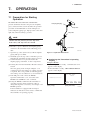
Preparation for Starting Operation ...................................................... 7-1
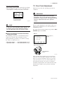
Zero Point Adjustment ........................................................................ 7-2
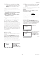
7.2.1 When you can obtain Low Range Value from actual
measured value of 0% (0 kPa, atmospheric pressure); .............. 7-3
7.2.2 When you cannot obtain Low Range Value from actual
measured value of 0%; ................................................................ 7-3
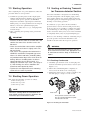
7.3 Starting Operation ............................................................................... 7-4
7.4 Shutting Down Operation .................................................................... 7-4
7.5 Venting or Draining Transmitter Pressure-detector Section ............... 7-4
7.5.1 Draining Condensate .................................................................... 7-4
7.5.2 Venting Gas .................................................................................. 7-5
7.6 Setting the Range Using the Range-setting Switch ........................... 7-5
8.
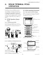
BRAIN TERMINAL BT200 OPERATION ..................................................... 8-1
8.1
BT200 Operation Precautions ............................................................. 8-1
8.1.1 Connecting the BT200 ................................................................. 8-1
8.1.2 Conditions of Communication Line .............................................. 8-1
8.2 BT200 Operating Procedures ............................................................. 8-1
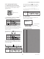
8.2.1 Key Layout and Screen Display ................................................... 8-1
8.2.2 Operating Key Functions .............................................................. 8-2
(1) Alphanumeric Keys and Shift Keys .............................................. 8-2
(2) Function Keys ............................................................................... 8-2
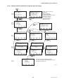
8.2.3 Calling Up Menu Addresses Using the Operating Keys .............. 8-3
8.3 Setting Parameters Using the BT200 ................................................. 8-4
8.3.1 Parameter Summary .................................................................... 8-4
8.3.2 Parameter Usage and Selection .................................................. 8-6
8.3.3 Setting Parameters ....................................................................... 8-7
(1) Tag No. Setup ............................................................................... 8-7
(2) Calibration Range Setup .............................................................. 8-7
(3) Damping Time Constant Setup ..................................................... 8-8
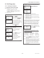
(4) Output Signal Low Cut Mode Setup ............................................. 8-9
(5) Change Output Limits ................................................................... 8-9
(6) Integral Indicator Scale Setup ...................................................... 8-9
(7) Unit Setup for Displayed Temperature ........................................ 8-11
(8) Operation Mode Setup ............................................................... 8-11
(9) Output Status Display/Setup when a CPU Failure ..................... 8-11
(10)Output Status Setup when a Hardware Error Occurs ................. 8-11
(11)Range Change while Applying Actual Inputs .............................. 8-12
(12)Zero Point Adjustment ................................................................ 8-12
(13)Span Adjustment ........................................................................ 8-14
(14)Test Output Setup ....................................................................... 8-15
(15)User Memo Fields ...................................................................... 8-15
ii
IM 01C21D01-01E
CONTENTS
8.4
Displaying Data Using the BT200 ..................................................... 8-15
8.4.1 Displaying Measured Data ......................................................... 8-15
8.4.2 Display Transmitter Model and Specifications ........................... 8-15
8.5 Self-Diagnostics ................................................................................ 8-16
8.5.1 Checking for Problems ............................................................... 8-16
(1) Identifying Problems with BT200 ................................................ 8-16
(2) Checking with Integral Indicator ................................................. 8-17
8.5.2 Errors and Countermeasures ..................................................... 8-18
9.
MAINTENANCE ............................................................................................. 9-1
9.1
9.2
9.3
9.4
Overview ............................................................................................. 9-1
Calibration Instruments Selection ....................................................... 9-1
Calibration ........................................................................................... 9-1
Disassembly and Reassembly ............................................................ 9-3
9.4.1 Replacing the Integral Indicator ................................................... 9-3
9.4.2 Replacing the CPU Board Assembly ........................................... 9-4
9.4.3 Cleaning and Replacing the Capsule Assembly .......................... 9-5
9.4.4 Replacing the Process Connector Gaskets ................................. 9-6
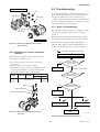
9.5 Troubleshooting ................................................................................... 9-6
9.5.1 Basic Troubleshooting .................................................................. 9-6
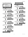
9.5.2 Troubleshooting Flow Charts ....................................................... 9-7
10. GENERAL SPECIFICATIONS .................................................................... 10-1
10.1
10.2
10.3
10.4
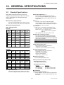
Standard Specifications .................................................................... 10-1
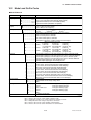
Model and Suffix Codes .................................................................... 10-3
Optional Specifications ...................................................................... 10-6
Dimensions ........................................................................................ 10-9
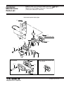
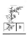
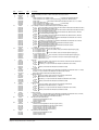
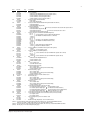
Customer Maintenance Parts List
DPharp EJA Series Transmitter Section ........................ CMPL 01C21A01-02E
Model EJA310A, EJA430A and EJA440A
Absolute and Gauge Pressure Transmitter ................... CMPL 01C21D00-01E
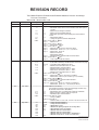
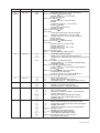
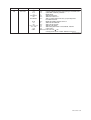
REVISION RECORD
iii
IM 01C21D01-01E
1. INTRODUCTION
1.
INTRODUCTION
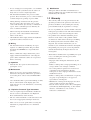
Thank you for purchasing the DPharp electronic
pressure transmitter.
• The following safety symbol marks are used in this
manual:
The DPharp Pressure Transmitters are precisely
calibrated at the factory before shipment. To ensure
correct and efficient use of the instrument, please read
this manual thoroughly and fully understand how to
operate the instrument before operating it.
WARNING
Indicates a potentially hazardous situation which,
if not avoided, could result in death or serious
injury.
Regarding This Manual
• This manual should be passed on to the end user.
• The contents of this manual are subject to change
without prior notice.
CAUTION
Indicates a potentially hazardous situation which,
if not avoided, may result in minor or moderate
injury. It may also be used to alert against
unsafe practices.
• All rights reserved. No part of this manual may be
reproduced in any form without Yokogawa’s written
permission.
• Yokogawa makes no warranty of any kind with
regard to this manual, including, but not limited to,
implied warranty of merchantability and fitness for a
particular purpose.
IMPORTANT
• If any question arises or errors are found, or if any
information is missing from this manual, please
inform the nearest Yokogawa sales office.
Indicates that operating the hardware or software
in this manner may damage it or lead to system
failure.
• The specifications covered by this manual are
limited to those for the standard type under the
specified model number break-down and do not
cover custom-made instruments.
NOTE
Draws attention to information essential for
understanding the operation and features.
• Please note that changes in the specifications,
construction, or component parts of the instrument
may not immediately be reflected in this manual at
the time of change, provided that postponement of
revisions will not cause difficulty to the user from a
functional or performance standpoint.
• Yokogawa assumes no responsibilities for this
product except as stated in the warranty.
• If the customer or any third party is harmed by the
use of this product, Yokogawa assumes no responsibility for any such harm owing to any defects in the
product which were not predictable, or for any
indirect damages.
Direct current
1.1 For Safe Use of Product
For the protection and safety of the operator and the
instrument or the system including the instrument,
please be sure to follow the instructions on safety
described in this manual when handling this instrument. In case the instrument is handled in contradiction
to these instructions, Yokogawa does not guarantee
safety. Please give your attention to the followings.
NOTE
(a) Installation
• The instrument must be installed by an expert
engineer or a skilled personnel. The procedures
described about INSTALLATION are not permitted
for operators.
For FOUNDATION FieldbusTM, PROFIBUS PA and
HART protocol versions, please refer to IM
01C22T02-01E, IM 01C22T03-00E and IM
01C22T01-01E respectively, in addition to this
manual.
1-1
IM 01C21D01-01E
1. INTRODUCTION
(f) Modification
• Yokogawa will not be liable for malfunctions or
damage resulting from any modification made to this
instrument by the customer.
• In case of high process temperature, care should be
taken not to burn yourself because the surface of
body and case reaches a high temperature.
• The instrument installed in the process is under
pressure. Never loosen the process connector bolts to
avoid the dangerous spouting of process fluid.
1.2 Warranty
• The warranty shall cover the period noted on the
quotation presented to the purchaser at the time of
purchase. Problems occurred during the warranty
period shall basically be repaired free of charge.
• During draining condensate from the pressuredetector section, take appropriate care to avoid
contact with the skin, eyes or body, or inhalation of
vapors, if the accumulated process fluid may be
toxic or otherwise harmful.
• In case of problems, the customer should contact the
Yokogawa representative from which the instrument
was purchased, or the nearest Yokogawa office.
• When removing the instrument from hazardous
processes, avoid contact with the fluid and the
interior of the meter.
• If a problem arises with this instrument, please
inform us of the nature of the problem and the
circumstances under which it developed, including
the model specification and serial number. Any
diagrams, data and other information you can
include in your communication will also be helpful.
• All installation shall comply with local installation
requirement and local electrical code.
(b) Wiring
• The instrument must be installed by an expert
engineer or a skilled personnel. The procedures
described about WIRING are not permitted for
operators.
• Responsible party for repair cost for the problems
shall be determined by Yokogawa based on our
investigation.
• Please confirm that voltages between the power
supply and the instrument before connecting the
power cables and that the cables are not powered
before connecting.
• The Purchaser shall bear the responsibility for repair
costs, even during the warranty period, if the
malfunction is due to:
- Improper and/or inadequate maintenance by the
purchaser.
- Failure or damage due to improper handling, use or
storage which is out of design conditions.
- Use of the product in question in a location not
conforming to the standards specified by
Yokogawa, or due to improper maintenance of the
installation location.
- Failure or damage due to modification or repair by
any party except Yokogawa or an approved
representative of Yokogawa.
- Malfunction or damage from improper relocation
of the product in question after delivery.
- Reason of force majeure such as fires, earthquakes,
storms/floods, thunder/lightening, or other natural
disasters, or disturbances, riots, warfare, or
radioactive contamination.
(c) Operation
• Wait 10 min. after power is turned off, before
opening the covers.
(d) Maintenance
• Please do not carry out except being written to a
maintenance descriptions. When these procedures
are needed, please contact nearest YOKOGAWA
office.
• Care should be taken to prevent the build up of drift,
dust or other material on the display glass and
name plate. In case of its maintenance, soft and dry
cloth is used.
(e) Explosion Protected Type Instrument
• Users of explosion proof instruments should refer
first to section 2.9 (Installation of an Explosion
Protected Instrument) of this manual.
• The use of this instrument is restricted to those who
have received appropriate training in the device.
• Take care not to create sparks when accessing the
instrument or peripheral devices in a hazardous
location.
1-2
IM 01C21D01-01E
1. INTRODUCTION
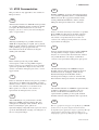
1.3 ATEX Documentation
SF
This procedure is only applicable to the countries in
European Union.
Kaikkien ATEX Ex -tyyppisten tuotteiden käyttöhjeet
ovat saatavilla englannin-, saksan- ja ranskankielisinä.
Mikäli tarvitsette Ex -tyyppisten tuotteiden ohjeita
omalla paikallisella kielellännne, ottakaa yhteyttä
lähimpään Yokogawa-toimistoon tai -edustajaan.
GB
All instruction manuals for ATEX Ex related products
are available in English, German and French. Should
you require Ex related instructions in your local
language, you are to contact your nearest Yokogawa
office or representative.
P
Todos os manuais de instruções referentes aos produtos
Ex da ATEX estão disponíveis em Inglês, Alemão e
Francês. Se necessitar de instruções na sua língua
relacionadas com produtos Ex, deverá entrar em
contacto com a delegação mais próxima ou com um
representante da Yokogawa.
DK
Alle brugervejledninger for produkter relateret til
ATEX Ex er tilgængelige på engelsk, tysk og fransk.
Skulle De ønske yderligere oplysninger om håndtering
af Ex produkter på eget sprog, kan De rette
henvendelse herom til den nærmeste Yokogawa
afdeling eller forhandler.
F
Tous les manuels d’instruction des produits ATEX Ex
sont disponibles en langue anglaise, allemande et
française. Si vous nécessitez des instructions relatives
aux produits Ex dans votre langue, veuillez bien
contacter votre représentant Yokogawa le plus proche.
I
Tutti i manuali operativi di prodotti ATEX
contrassegnati con Ex sono disponibili in inglese,
tedesco e francese. Se si desidera ricevere i manuali
operativi di prodotti Ex in lingua locale, mettersi in
contatto con l’ufficio Yokogawa più vicino o con un
rappresentante.
D
Alle Betriebsanleitungen für ATEX Ex bezogene
Produkte stehen in den Sprachen Englisch, Deutsch
und Französisch zur Verfügung. Sollten Sie die
Betriebsanleitungen für Ex-Produkte in Ihrer
Landessprache benötigen, setzen Sie sich bitte mit
Ihrem örtlichen Yokogawa-Vertreter in Verbindung.
E
Todos los manuales de instrucciones para los productos
antiexplosivos de ATEX están disponibles en inglés,
alemán y francés. Si desea solicitar las instrucciones de
estos artículos antiexplosivos en su idioma local,
deberá ponerse en contacto con la oficina o el
representante de Yokogawa más cercano.
S
Alla instruktionsböcker för ATEX Ex (explosionssäkra)
produkter är tillgängliga på engelska, tyska och
franska. Om Ni behöver instruktioner för dessa
explosionssäkra produkter på annat språk, skall Ni
kontakta närmaste Yokogawakontor eller representant.
NL
Alle handleidingen voor producten die te maken
hebben met ATEX explosiebeveiliging (Ex) zijn
verkrijgbaar in het Engels, Duits en Frans. Neem,
indien u aanwijzingen op het gebied van
explosiebeveiliging nodig hebt in uw eigen taal, contact
op met de dichtstbijzijnde vestiging van Yokogawa of
met een vertegenwoordiger.
GR
ATEX Ex
, .
Ex Yokogawa .
1-3
IM 01C21D01-01E
1. INTRODUCTION
PL
SK
CZ
SLO
H
LT
BG
LV
RO
EST
M
1-4
IM 01C21D01-01E
2. HANDLING CAUTIONS
2.
HANDLING CAUTIONS
This chapter describes important cautions regarding
how to handle the transmitter. Read carefully before
using the transmitter.
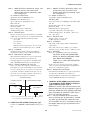
The EJA-A Series pressure transmitters are thoroughly
tested at the factory before shipment. When the
transmitter is delivered, visually check them to make
sure that no damage occurred during shipment.
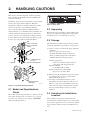
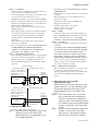
Also check that all transmitter mounting hardware
shown in Figure 2.1 is included. If the transmitter was
ordered without the mounting bracket or without the
process connector, the transmitter mounting hardware
is not included. After checking the transmitter, repack
it in the way it was delivered until installation.
Bolt
Process connector
: Refer to USER'S MANUAL
F0202.EPS
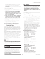
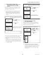
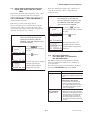
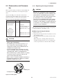
Figure 2.2 Name Plate
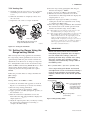
2.2 Unpacking
When moving the transmitter to the installation site,
keep it in its original packaging. Then, unpack the
transmitter there to avoid damage on the way.
2.3 Storage
The following precautions must be observed when
storing the instrument, especially for a long period.
Process connector
Gasket
(a) Select a storage area which meets the following
conditions:
• It is not exposed to rain or water.
• It suffers minimum vibration and shock.
• It has an ambient temperature and relative
humidity within the following ranges.
U-bolt
Mounting bracket
(L type)
U-bolt nut
Ambient temperature:
–40 to 85°C without integral indicator
–30 to 80°C with integral indicator
Relative humidity:
5% to 100% R.H. (at 40°C)
Preferred temperature and humidity:
approx. 25°C and 65% R.H.
Transmitter mounting bolt
Mounting bracket
(Flat type)
F0201.EPS
Figure 2.1 Transmitter Mounting Hardware
2.1 Model and Specifications
Check
The model name and specifications are indicated on the
name plate attached to the case. If the reverse operating mode was ordered (reverse signal), ‘REVERSE’
will be inscribed in field *1.
(b) When storing the transmitter, repack it as nearly
as possible to the way it was packed when
delivered from the factory.
(c) If storing a transmitter that has been used,
thoroughly clean the chambers inside the cover
flanges, so that no measured fluid remains in it.
Also make sure before storing that the pressuredetector and transmitter section are securely
mounted.
2.4 Selecting the Installation
Location
The transmitter is designed to withstand severe
environmental conditions. However, to ensure stable
and accurate operation for years, observe the following precautions when selecting an installation location.
2-1
IM 01C21D01-01E
2. HANDLING CAUTIONS
(a) Ambient Temperature
Avoid locations subject to wide temperature
variations or a significant temperature gradient. If
the location is exposed to radiant heat from plant
equipments, provide adequate thermal insulation
and/or ventilation.
(b) Ambient Atmosphere
Avoid installing the transmitter in a corrosive
atmosphere. If the transmitter must be installed in a
corrosive atmosphere, there must be adequate
ventilation as well as measures to prevent intrusion
or stagnation of rain water in conduits.
(c) Shock and Vibration
Select an installation site suffering minimum shock
and vibration (although the transmitter is designed
to be relatively resistant to shock and vibration).
(d) Installation of Explosion-protected Transmitters
Explosion-protected transmitters can be installed in
hazardous areas according to the types of gases for
which they are certified. See Subsection 2.9
“Installation of Explosion Protected Type Transmitters.”
2.5 Pressure Connection
WARNING
• Instrument installed in the process is under
pressure. Never loosen the process connector
bolts to avoid the dangerous spouting of
process fluid.
• During draining condensate from the pressuredetector section, take appropriate care to avoid
contact with the skin, eyes or body, or inhalation of vapors, if the accumulated process fluid
may be toxic or otherwise harmful.
The following precautions must be observed in order to
safely operate the transmitter under pressure.
(a) Make sure that the two process connector bolts are
tightened firmly.
(b) Make sure that there are no leaks in the impulse
piping.
(c) Never apply a pressure higher than the specified
maximum working pressure.
2.6 Waterproofing of Cable
Conduit Connections
Apply a non-hardening sealant to the threads to
waterproof the transmitter cable conduit connections.
(See Figure 6.4.2a, 6.4.2b and 6.4.2c.)
2.7 Restrictions on Use of Radio
Transceiver
IMPORTANT
Although the transmitter has been designed to
resist high frequency electrical noise, if a radio
transceiver is used near the transmitter or its
external wiring, the transmitter may be affected
by high frequency noise pickup. To test for such
effects, bring the transceiver in use slowly from a
distance of several meters from the transmitter,
and observe the measurement loop for noise
effects. Thereafter, always use the transceiver
outside the area affected by noise.
2.8 Insulation Resistance and
Dielectric Strength Test
Since the transmitter has undergone insulation resistance and dielectric strength tests at the factory before
shipment, normally these tests are not required.
However, if required, observe the following precautions in the test procedures.
(a) Do not perform such tests more frequently than is
absolutely necessary. Even test voltages that do not
cause visible damage to the insulation may degrade
the insulation and reduce safety margins.
(b) Never apply a voltage exceeding 500 V DC (100 V
DC with an internal lightning protector) for the
insulation resistance test, nor a voltage exceeding
500 V AC (100 V AC with an internal lightning
protector) for the dielectric strength test.
(c) Before conducting these tests, disconnect all signal
lines from the transmitter terminals. Perform the
tests in the following procedure:
• Insulation Resistance Test
1) Short-circuit the + and – SUPPLY terminals in the
terminal box.
2) Turn OFF the insulation tester. Then connect the
insulation tester plus (+) lead wire to the shorted
SUPPLY terminals and the minus (–) leadwire to
the grounding terminal.
3) Turn ON the insulation tester power and measure
the insulation resistance. The voltage should be
applied short as possible to verify that the insulation resistance is at least 20 MΩ.
4) After completing the test and being very careful not
to touch exposed conductors disconnect the
insulation tester and connect a 100 kΩ resistor
between the grounding terminal and the short2-2
IM 01C21D01-01E
2. HANDLING CAUTIONS
circuiting SUPPLY terminals. Leave this resistor
connected at least one second to discharge any
static potential. Do not touch the terminals while it
is discharging.
• Dielectric Strength Test
1) Short-circuit the + and – SUPPLY terminals in the
terminal box.
2) Turn OFF the dielectric strength tester. Then
connect the tester between the shorted SUPPLY
terminals and the grounding terminal. Be sure to
connect the grounding lead of the dielectric strength
tester to the ground terminal.
3) Set the current limit on the dielectric strength tester
to 10 mA, then turn ON the power and gradually
increase the test voltage from ‘0’ to the specified
voltage.
4) When the specified voltage is reached, hold it for
one minute.
5) After completing this test, slowly decrease the
voltage to avoid any voltage surges.
2.9 Installation of Explosion
Protected Type
In this section, further requirements and differences
and for explosionproof type instrument are described.
For explosionproof type instrument, the description in
this chapter is prior to other description in this users
manual.
For the intrinsically safe equipment and explosionproof
equipment, in case the instrument is not restored to its
original condition after any repair or modification
undertaken by the customer, intrinsically safe construction or explosionproof construction is damaged and
may cause dangerous condition. Please contact
Yokogawa for any repair or modification required to
the instrument.
NOTE
For FOUNDATION Fieldbus and PROFIBUS PA
explosion protected type, please refer to IM
01C22T02-01E and IM 01C22T03-00E respectively.
CAUTION
This instrument is tested and certified as intrinsically safe type or explosionproof type. Please
note that the construction of the instrument,
installation, external wiring, maintenance or
repair is strictly restricted, `Êå non-observance
or negligence of this restriction would result in
dangerous condition.
WARNING
To preserve the safety of explosionproof equipment requires great care during mounting,
wiring, and piping. Safety requirements also
place restrictions on maintenance and repair
activitic¤¶ Please read the following sections very
carefully.
2.9.1 FM Approval
a. FM Intrinsically Safe Type
Caution for FM intrinsically safe type. (Following
contents refer “DOC. No. IFM012-A12 P.1 and 2.”)
Note 1. Model EJA Series pressure transmitters
with optional code /FS1 are applicable for
use in hazardous locations.
• Applicable Standard: FM3600, FM3610, FM3611,
FM3810, ANSI/NEMA250
• Intrinsically Safe for Class I, Division 1, Groups A,
B, C & D. Class II, Division 1, Groups E, F & G
and Class III, Division 1 Hazardous Locations.
• Nonincendive for Class I, Division 2, Groups A, B,
C & D. Class II, Division 2, Groups E, F & G and
Class III, Division 1 Hazardous Locations.
• Outdoor hazardous locations, NEMA 4X.
• Temperature Class: T4
• Ambient temperature: –40 to 60°C
Note 2. Entity Parameters
• Intrinsically Safe Apparatus Parameters
[Groups A, B, C, D, E, F and G]
Vmax = 30 V
Ci = 22.5 nF
Imax = 165 mA
Li = 730 µH
Pmax = 0.9 W
* Associated Apparatus Parameters
(FM approved barriers)
Voc ≤ 30 V
Ca > 22.5 nF
Isc ≤ 165 mA
La > 730 µH
Pmax ≤ 0.9W
• Intrinsically Safe Apparatus Parameters
[Groups C, D, E, F and G]
Vmax = 30 V
Ci = 22.5 nF
Imax = 225 mA
Li = 730 µH
Pmax = 0.9 W
* Associated Apparatus Parameters
(FM approved barriers)
Voc ≤ 30 V
Ca > 22.5 nF
Isc ≤ 225 mA
La > 730 µH
Pmax ≤ 0.9 W
• Entity Installation Requirements
Vmax ≥ Voc or Vt, Imax ≥ Isc or It,
Pmax (IS Apparatus) ≥ Pmax (Barrier)
Ca ≥ Ci + Ccable, La ≥ Li + Lcable
2-3
IM 01C21D01-01E
2. HANDLING CAUTIONS
Note 3. Installation
• Barrier must be installed in an enclosure that meets
the requirements of ANSI/ISA S82.01.
• Control equipment connected to barrier must not use
or generate more than 250 V rms or V dc.
• Installation should be in accordance with ANSI/ISA
RP12.6 “Installation of Intrinsically Safe Systems for
Hazardous (Classified) Locations” and the National
Electric Code (ANSI/NFPA 70).
• The configuration of associated apparatus must be
FMRC Approved.
• Dust-tight conduit seal must be used when installed
in a Class II, III, Group E, F and G environments.
• Associated apparatus manufacturer’s installation
drawing must be followed when installing this
apparatus.
• The maximum power delivered from the barrier
must not exceed 0.9 W.
• Note a warning label worded “SUBSTITUTION OF
COMPONENTS MAY IMPAIR INTRINSIC
SAFETY,” and “INSTALL IN ACCORDANCE
WITH DOC. No. IFM012-A12 P.1 and 2.”
Note 4. Maintenance and Repair
• The instrument modification or parts replacement by
other than authorized representative of Yokogawa
Electric Corporation is prohibited and will void
Factory Mutual Intrinsically safe and Nonincendive
Approval.
• Applicable Standard: FM3600, FM3615, FM3810,
ANSI/NEMA250
• Explosionproof for Class I, Division 1, Groups B,
C and D.
• Dust-ignitionproof for Class II/III, Division 1,
Groups E, F and G.
• Outdoor hazardous locations, NEMA 4X.
• Temperature Class: T6
• Ambient Temperature: –40 to 60°C
• Supply Voltage: 42 V dc max.
• Output signal: 4 to 20 mA
Note 2. Wiring
• All wiring shall comply with National Electrical
Code ANSI/NEPA70 and Local Electrical Codes.
• When installed in Division 1, “FACTORY
SEALED, CONDUIT SEAL NOT REQUIRED.”
Note 3. Operation
• Keep the “CAUTION” nameplate attached to the
transmitter.
CAUTION: OPEN CIRCUIT BEFORE REMOVING COVER. SEAL ALL CONDUITS WITHIN
18 INCHES. WHEN INSTALLED IN DIV.1,
“FACTORY SEALED, CONDUIT SEAL NOT
REQUIRED.” INSTALL IN ACCORDANCE
WITH THE INSTRUCTION MANUAL IM 1C22.
• Take care not to generate mechanical sparking
when accessing to the instrument and peripheral
devices in a hazardous location.
Note 4. Maintenance and Repair
• The instrument modification or parts replacement
by other than authorized representative of
Yokogawa Electric Corporation is prohibited and
will void Factory Mutual Explosionproof Approval.
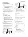
[Intrinsically Safe]
Hazardous Location
Nonhazardous Location
Class I, II, III, Division 1,
Groups A, B, C, D, E, F, G
EJA Series Pressure
Transmitters
+
Supply
–
Safety Barrier
+
+
–
–
General
Purpose
Equipment
+
–
c. FM Intrinsically Safe Type/FM
Explosionproof Type
Model EJA Series pressure transmitters with
optional code /FU1 can be selected the type
of protection (FM Intrinsically Safe or FM
Explosionproof) for use in hazardous locations.
Note 1. For the installation of this transmitter,
once a particular type of protection is
selected, any other type of protection
cannot be used. The installation must be
in accordance with the description about
the type of protection in this instruction
manual.
Note 2. In order to avoid confusion, unnecessary
marking is crossed out on the label
other than the selected type of protection when the transmitter is installed.
F0203-1.EPS
[Nonincendive]
Hazardous Location
Nonhazardous Location
Class I, II, Division 2,
Groups A, B, C, D, E, F, G
Class III, Division 1.
General
Purpose
Equipment
EJA Series Pressure
Transmitters
+
Supply
+
–
–
Not Use
Safety Barrier
F0203-2.EPS
b. FM Explosionproof Type
Caution for FM explosionproof type.
Note 1. Model EJA Series differential, gauge, and
absolute pressure transmitters with
optional code /FF1 are applicable for use
in hazardous locations.
2-4
IM 01C21D01-01E
2. HANDLING CAUTIONS
2.9.2 CSA Certification
[Nonincendive]
Hazardous Location
a. CSA Intrinsically Safe Type
Caution for CSA Intrinsically safe type. (Following
contents refer to “DOC No. ICS003-A12 P.1-1 and
P.1-2.”)
Note 1. Model EJA Series differential, gauge, and
absolute pressure transmitters with
optional code /CS1 are applicable for use
in hazardous locations
Certificate: 1053843
• Applicable Standard: C22.2 No.0, No.0.4, No.25,
No.30, No.94, No.142, No.157, No.213
• Intrinsically Safe for Class I, Division 1, Groups A,
B, C & D. Class II, Division 1, Groups E, F & G
and Class III, Division 1 Hazardous Locations.
• Nonincendive for Class I, Division 2, Groups A, B,
C & D, Class II, Division 2, Groups F & G, and
Class III, Hazardous Locations. (not use Safety
Barrier)
• Encl. “Type 4X”
• Temperature Class: T4
• Ambient temperature: –40 to 60°C
• Process Temperature: 120°C max.
Note 2. Entity Parameters
• Intrinsically safe ratings are as follows:
Maximum Input Voltage (Vmax) = 30 V
Maximum Input Current (Imax) = 165 mA
Maximum Input Power (Pmax) = 0.9 W
Maximum Internal Capacitance (Ci) = 22.5 nF
Maximum Internal Inductance (Li) = 730 µH
* Associated apparatus (CSA certified barriers)
Maximum output voltage (Voc) ≤ 30 V
Maximum output current (Isc) ≤ 165 mA
Maximum output power (Pmax) ≤ 0.9 W
Note 3. Installation
• All wiring shall comply with Canadian Electrical
Code Part I and Local Electrical Codes.
• The instrument modification or parts replacement
by other than authorized representative of
Yokogawa Electric Corporation and Yokogawa
Corporation of America is prohibited and will void
Canadian Standards Intrinsically safe and
nonincendive Certification.
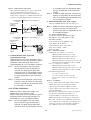
[Intrinsically Safe]
Hazardous Location
Nonhazardous Location
Class I, II, III, Division 1,
Groups A, B, C, D, E, F, G
EJA Series Pressure
Transmitters
+
Supply
–
Safety Barrier
+
+
–
–
General
Purpose
Equipment
+
–
Nonhazardous Location
Class I, II, Division 2,
Groups A, B, C, D, E, F, G
Class III, Division 1.
General
Purpose
Equipment
EJA Series Pressure
Transmitters
+
Supply
+
–
–
Not Use
Safety Barrier
F0204-2.EPS
b. CSA Explosionproof Type
Caution for CSA explosionproof type.
Note 1. Model EJA Series differential, gauge, and
absolute pressure transmitters with
optional code /CF1 are applicable for use
in hazardous locations:
Certificate: 1089598
• Applicable Standard: C22.2 No.0, No.0.4, No.25,
No.30, No.94, No.142
• Explosionproof for Class I, Division 1, Groups B,
C and D.
• Dust-ignitionproof for Class II/III, Division 1,
Groups E, F and G.
• Encl “Type 4X”
• Temperature Class: T6, T5, and T4
• Process Temperature: 85°C (T6), 100°C (T5), and
120°C (T4)
• Ambient Temperature: –40 to 80°C
• Supply Voltage: 42 V dc max.
• Output Signal: 4 to 20 mA
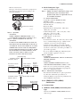
Note 2. Wiring
• All wiring shall comply with Canadian Electrical
Code Part I and Local Electrical Codes.
• In hazardous location, wiring shall be in conduit as
shown in the figure.
CAUTION: SEAL ALL CONDUITS
WITHIN 50 cm OF THE ENCLOSURE.
UN SCELLEMENT DOIT ÊTRE
INSTALLÉ À MOINS DE 50 cm DU
BÎTIER.
• When installed in Division 2, “SEALS NOT
REQUIRED.”
Note 3. Operation
• Keep the “CAUTION” label attached to the
transmitter.
CAUTION: OPEN CIRCUIT BEFORE
REMOVING COVER.
OUVRIR LE CIRCUIT AVANT
D´NLEVER LE COUVERCLE.
• Take care not to generate mechanical sparking
when accessing to the instrument and peripheral
devices in a hazardous location.
F0204-1.EPS
2-5
IM 01C21D01-01E
2. HANDLING CAUTIONS
Note 4. Maintenance and Repair
• The instrument modification or parts replacement
by other than authorized representative of
Yokogawa Electric Corporation and Yokogawa
Corporation of America is prohibited and will void
Canadian Standards Explosionproof Certification.
Non-Hazardous Hazardous Locations Division 1
Locations
Non-hazardous
Location
Equipment
42 V DC Max.
4 to 20 mA DC
Signal
50 cm Max.
Sealing Fitting
Conduit
EJA Series
Non-Hazardous Hazardous Locations Division 2
Locations
Non-hazardous
Location
Equipment
42 V DC Max.
4 to 20 mA DC
Signal
Sealing Fitting
EJA Series
F0205.EPS
c. CSA Intrinsically Safe Type/CSA
Explosionproof Type
Model EJA Series pressure transmitters with
optional code /CU1 can be selected the type of
protection (CSA Intrinsically Safe or CSA
Explosionproof) for use in hazardous locations.
Note 1. For the installation of this transmitter,
once a particular type of protection is
selected, any other type of protection
cannot be used. The installation must be
in accordance with the description about
the type of protection in this instruction
manual.
Note 2. In order to avoid confusion, unnecessary
marking is crossed out on the label other
than the selected type of protection when
the transmitter is installed.
2.9.3 IECEx Certification
Model EJA Series differential, gauge, and
absolute pressure transmitters with
optional code /SU2 can be selected the type of
protection (IECEx Intrinsically Safe/type n or
flameproof) for use in hazardous locations.
Note 1. For the installation of this transmitter,
once a particular type of protection is
selected, any other type of protection
cannot be used. The installation must be
in accordance with the description about
the type of protection in this instruction
manual.
Note 2. In order to avoid confusion, unnecessary
marking is crossed out on the label other
than the selected type of protection when
the transmitter is installed.
a. IECEx Intrinsically Safe Type / type n
Caution for IECEx Intrinsically safe and type n.
Note 1. Model EJA Series differential, gauge, and
absolute pressure transmitters with
optional code /SU2 are applicable for use
in hazardous locations.
• No. IECEx KEM 06.0007X
• Applicable Standard: IEC 60079-0:2004,
IEC 60079-11:1999, IEC 60079-15:2005,
IEC 60079-26:2004
• Type of Protection and Marking Code:
Ex ia IIC T4, Ex nL IIC T4
• Ambient Temperature :–40 to 60°C
• Max. Process Temp.: 120°C
• Enclosure: IP67
Note 2. Entity Parameters
• Intrinsically safe ratings are as follows:
Maximum Input Voltage (Ui) = 30 V
Maximum Input Current (Ii) = 165 mA
Maximum Input Power (Pi) = 0.9 W
Maximum Internal Capacitance (Ci) = 22.5 nF
Maximum Internal Inductance (Li) = 730 µH
• Type "n" ratings are as follows:
Maximum Input Voltage (Ui) = 30 V
Maximum Internal Capacitance (Ci) = 22.5 nF
Maximum Internal Inductance (Li) = 730 µH
• Installation Requirements
Uo ≤ Ui, Io ≤ Ii, Po ≤ Pi,
Co ≥ Ci + Ccable, Lo ≥ Li + Lcable
Uo, Io, Po, Co, and Lo are parameters of
barrier.
Note 3. Installation
• In any safety barreir used output current must be
limited by a resistor 'R' such that Io=Uo/R.
• The safety barrier must be IECEx certified.
• Input voltage of the safety barrier must be less
than 250 Vrms/Vdc.
• The instrument modification or parts replacement
by other than authorized representative of
Yokogawa Electric Corporation and will void
IECEx Intrinsically safe and type n certification.
• The cable entry devices and blanking elements for
type n shall be of a certified type providing a level
of ingress protection of at least IP54, suitable for
the conditions of use and correctly installed.
2-6
IM 01C21D01-01E
2. HANDLING CAUTIONS
• Electrical Connection:
The type of electrical connection is stamped near
the electrical connection port according to the
following marking.
T0202.EPS
Location of the marking
F0210.EPS
Note 4. Operation
• WARNING:
WHEN AMBIENT TEMPERATURE ≥ 55°C,
USE THE HEAT-RESISTING CABLES ≥ 90°C.
Note 5. Special Conditions for Safe Use
• WARNING:
IN THE CASE WHERE THE ENCLOSURE OF
THE PRESSURE TRANSMITTER IS MADE OF
ALUMINUM, IF IT IS MOUNTED IN AN AREA
WHERE THE USE OF ZONE 0 IS REQUIRED,
IT MUST BE INSTALLED SUCH, THAT, EVEN
IN THE EVENT OF RARE INCIDENTS, IGNITION SOURCES DUE TO IMPACT AND
FRICTION SPARKS ARE EXCLUDED.
[Intrinsically Safe]
Hazardous Location
Nonhazardous Location
Group I/IIC, Zone 0
IECEx certified
Safety Barrier
+
+
EJA Series Pressure
Transmitters
+
–
Supply
–
General
Purpose
Equipment
+
–
–
F0211.EPS
[type n]
Hazardous Location
Nonhazardous Location
Group IIC, Zone 2
IECEx Certified
Equipment [nL]
EJA Series Pressure
Transmitters
+
Supply
b. IECEx Flameproof Type
Caution for IECEx flameproof type.
Note 1. Model EJA Series differential, gauge, and
absolute pressure transmitters with
optional code /SU2 are applicable for use
in hazardous locations:
• No. IECEx KEM 06.0005
• Applicable Standard: IEC60079-0:2004,
IEC60079-1:2003
• Type of Protection and Marking Code:
Ex d IIC T6...T4
• Enclosure: IP67
• Maximum Process Temperature: 120°C (T4),
100°C (T5), 85°C (T6)
• Ambient Temperature: –40 to 75°C (T4), –40 to
80°C (T5), –40 to 75°C (T6)
• Supply Voltage: 42 V dc max.
• Output Signal: 4 to 20 mA dc
Note 2. Wiring
• In hazardous locations, the cable entry devices shall
be of a certified flameproof type, suitable for the
conditions of use and correctly installed.
• Unused apertures shall be closed with suitable
flameproof certified blanking elements. (The plug
attached is certificated as the flame proof IP67 as a
part of this apparatus.)
• In case of ANSI 1/2 NPT plug, ANSI hexagonal
wrench should be applied to screw in.
Note 3. Operation
• WARNING:
AFTER DE-ENERGIZING, DELAY 10 MINUTES
BEFORE OPENING.
• WARNING:
WHEN AMBIENT TEMPERATURE ≥ 70°C,
USE THE HEAT-RESISTING CABLES ≥ 90°C.
• Take care not to generate mechanical sparking
when accessing to the instrument and peripheral
devices in a hazardous location.
Note 4. Maintenance and Repair
• The instrument modification or parts replacement
by other than authorized representative of
Yokogawa Electric Corporation is prohibited and
will void IECEx Certification.
2.9.4 CENELEC ATEX (KEMA)
Certification
+
–
–
Not Use
Safety Barrier
F0212.EPS
(1) Technical Data
a. CENELEC ATEX (KEMA) Intrinsically Safe
Type
Caution for CENELEC ATEX (KEMA) Intrinsically safe type.
2-7
IM 01C21D01-01E
2. HANDLING CAUTIONS
Note 1. Model EJA Series differential, gauge, and
absolute pressure transmitters with
optional code /KS2 for potentially explosive atmospheres:
• No. KEMA 02ATEX1030 X
• Applicable Standard: EN50014:1997,
EN50020:1994, EN50284:1999
• Type of Protection and Marking code:
EEx ia IIC T4
• Temperature Class: T4
• Enclosure: IP67
• Process Temperature: 120°C max.
• Ambient Temperature: –40 to 60°C
Note 2. Electrical Data
• In type of explosion protection intrinsic safety EEx
ia IIC only for connection to a certified intrinsically
safe circuit with following maximum values:
Ui = 30 V
Ii = 165 mA
Pi = 0.9 W
Effective internal capacitance; Ci = 22.5 nF
Effective internal inductance; Li = 730 µH
Note 3. Installation
• All wiring shall comply with local installation
requirements. (Refer to the installation diagram)
Note 4. Maintenance and Repair
• The instrument modification or parts replacement
by other than authorized representative of
Yokogawa Electric Corporation is prohibited and
will void KEMA Intrinsically safe Certification.
Note 5. Special Conditions for Safe Use
• In the case where the enclosure of the Pressure
Transmitter is made of aluminium, if it is mounted
in an area where the use of category 1 G apparatus
is required, it must be installed such, that, even in
the event of rare incidents, ignition sources due to
impact and friction sparks are excluded.
[Installation Diagram]
Hazardous Location
Nonhazardous Location
Transmitter
+
+
–
–
Safety Barrier *1
Supply
F0208.EPS
*1: In any safety barriers used the output current must be limited
by a resistor “R” such that Imaxout-Uz/R.
b. CENELEC ATEX (KEMA) Flameproof Type
Caution for CENELEC ATEX (KEMA) flameproof
type.
Note 1. Model EJA Series differential, gauge, and
absolute pressure transmitters with
optional code /KF2 for potentially explosive atmospheres:
• No. KEMA 02ATEX2148
• Applicable Standard: EN50014:1997,
EN50018:2000
• Type of Protection and Marking Code: EEx d IIC
T6···T4
• Temperature Class: T6, T5, and T4
• Enclosure: IP67
• Maximum Process Temperature:
85°C (T6), 100°C (T5), and 120°C (T4)
• Ambient Temperature: T4 and T6; –40 to 75°C,
T5; –40 to 80°C
Note 2. Electrical Data
• Supply voltage: 42 V dc max.
• Output signal: 4 to 20 mA
Note 3. Installation
• All wiring shall comply with local installation
requirement.
• The cable entry devices shall be of a certified
flameproof type, suitable for the conditions of use.
Note 4. Operation
• Keep the “CAUTION” label to the transmitter.
CAUTION: AFTER DE-ENERGIZING,
DELAY 10 MINUTES BEFORE OPENING. WHEN THE AMBIENT
TEMP.70°C, USE HEAT-RESISTING
CABLES90°C.
• Take care not to generate mechanical sparking
when accessing to the instrument and peripheral
devices in a hazardous location.
Note 5. Maintenance and Repair
• The instrument modification or parts replacement
by other than authorized representative of
Yokogawa Electric Corporation is prohibited and
will void KEMA Flameproof Certification.
c. CENELEC ATEX (KEMA) Intrinsically Safe
Type/CENELEC ATEX (KEMA) Flameproof
Type/ CENELEC ATEX Type n
Model EJA-A Series pressure transmitters with
optional code /KU2 can be selected the type of
protection CENELEC ATEX (KEMA) Intrinsically
Safe, Flameproof or CENELEC ATEX Type n
for use in hazardous locations.
Note 1. For the installation of this transmitter,
once a particular type of protection is selected,
any other type of protection cannot be used.
The installation must be in accordance with the
description about the type of protection in this
user’s manual.
2-8
IM 01C21D01-01E
2. HANDLING CAUTIONS
Note 2. In order to avoid confusion, unnecessary
marking is crossed out on the label other than
the selected type of protection when the
transmitter is installed.
䊉 CENELEC ATEX Type of Protection “n”
WARNING
When using a power supply not having a nonincendive circuit, please pay attention not to
ignite in the surrounding flammable atmosphere.
In such a case, we recommend using wiring
metal conduit in order to prevent the ignition.
• Applicable Standard: EN60079-15
• Referential Standard: IEC60079-0, IEC60079-11
• Type of Protection and Marking Code:
Ex nC IIL T4
• Temperature Class: T4
• Enclosure: IP67
• Process Temperature: 120°C max.
• Ambient Temperature: –40 to 60°C
Note 1. Electrical Data
Ui = 30 V
Effective internal capacitance; Ci = 22.5 nF
Effective internal inductance; Li = 730 µH
Note 2. Installation
• All wiring shall comply with local installation
requirements. (refer to the installation diagram)
Note 3. Maintenance and Repair
• The instrument modification or parts replacement
by other than authorized representative of
Yokogawa Electric Corporation is prohibited and
will void Type of Protection “n”.
Note 1. Installation instructions
The cable entry devices and blanking elements
shall be of a certificated type providing a level
of ingress protection of at least IP6x, suitable
for the conditions of use and correctly installed.
(2) Electrical Connection
The type of electrical connection is stamped near
the electrical connection port according to the
following marking.
Location of the marking
F0200.EPS
(3) Installation
WARNING
• All wiring shall comply with local installation
requirement and local electrical code.
• There is no need of the conduit seal for both of
Division 1 and Division 2 hazardous locations
because this product is sealed at factory.
• In case of ANSI 1/2 NPT plug, ANSI hexagonal
wrench should be applied to screw in.
(4) Operation
WARNING
[Installation Diagram]
Hazardous Location
(Zone 2 only)
Transmitter
• OPEN CIRCUIT BEFORE REMOVING
COVER. INSTALL IN ACCORDANCE WITH
THIS USER’S MANUAL
• Take care not to generate mechanical sparking
when access to the instrument and peripheral
devices in hazardous locations.
Nonhazardous Location
+
+
–
–
Supply
Power Supply
(5) Maintenance and Repair
F0209.EPS
Ratings of the Power Supply as follows;
Maximum Voltage: 30 V
WARNING
The instrument modification or parts replacement
by other than authorized Representative of
Yokogawa Electric Corporation is prohibited and
will void the certification.
䊉 CENELEC ATEX Type of Protection “Dust”
• Applicable Standard: EN50281-1-1:1997
• Type of Protection and Marking Code: II 1D
• Maximum Surface Temperature:
T65°C (Tamb.: 40°C), T85°C (Tamb.: 60°C), and
T105°C (Tamb.: 80°C)
2-9
IM 01C21D01-01E
2. HANDLING CAUTIONS
(6) Name Plate
2.10EMC Conformity Standards
Name plate
EN61326-1 Class A, Table 2 (For use in industrial
locations)
EN61326-2-3
: Refer to USER'S MANUAL
CAUTION
Tag plate for flameproof type
This instrument is a Class A product, and it is
designed for use in the industrial environment.
Please use this instrument in the industrial
environment only.
Tag plate for intrinsically safe type
NOTE
YOKOGAWA recommends customer to apply
the Metal Conduit Wiring or to use the twisted
pair Shield Cable for signal wiring to conform the
requirement of EMC Regulation, when customer
installs the EJA Series Transmitters to the plant.
Tag plate for type n protection
Tag plate for flameproof, intrinsically safe type,
type n protection, and Dust
D
2.11 PED (Pressure Equipment
Directive)
T65⬚C (Tamb.: 40⬚C), T85⬚C (Tamb.: 60⬚C),
and T105⬚C (Tamb.: 80⬚C)
F0298.EPS
MODEL: Specified model code.
STYLE: Style code.
SUFFIX: Specified suffix code.
SUPPLY: Supply voltage.
OUTPUT: Output signal.
MWP: Maximum working pressure.
CAL RNG: Specified calibration range.
DISP MODE: Specified display mode.
OUTPUT MODE: Specified output mode.
NO.: Serial number and year of production*1.
TOKYO 180-8750 JAPAN:
The manufacturer name and the address*2.
*1: The third figure from the last shows the last one
figure of the year of production. For example, the
production year of the product engraved in “NO.”
column on the name plate as follows is 2001.
12A819857
132
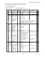
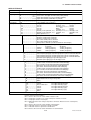
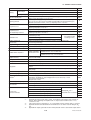
(1) General
• EJA series of pressure transmitters are categorized
as pressure accessories under the vessel section of
this directive 97/23/EC, which corresponds to
Article 3, Paragraph 3 of PED, denoted as Sound
Engineering Practice (SEP).
• EJA130A, EJA440A, EJA510A, and EJA530A can
be used above 200 bar and therefore considered as
a part of a pressure retaining vessel where category
lll, Module H applies. These models with option
code /PE3 conform to that category.
(2) Technical Data
• Models without /PE3
Article 3, Paragraph 3 of PED, denoted as Sound
Engineering Practice (SEP) .
• Models with /PE3
Module: H
Type of Equipment: Pressure Accessory - Vessel
Type of Fluid: Liquid and Gas
Group of Fluid: 1 and 2
The year 2001
*2: “180-8750” is a zip code which represents the
following address.
2-9-32 Nakacho, Musashino-shi, Tokyo Japan
2-10
IM 01C21D01-01E
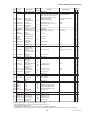
2. HANDLING CAUTIONS
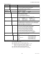
EJA110A
160
0.01
1.6
EJA120A
0.5
0.01
0.005
EJA130A
420
0.01
4.2
Category*2
Article 3, paragraph 3
(SEP)
Article 3, paragraph 3
(SEP)
Article 3, paragraph 3
(SEP)
EJA130A
With code /PE3
420
0.01
4.2
III
EJA310A
160
0.01
1.6
EJA430A
160
0.01
1.6
EJA440A
500
0.01
50
Article 3, paragraph 3
(SEP)
Article 3, paragraph 3
(SEP)
Article 3, paragraph 3
(SEP)
EJA440A
With code /PE3
500
0.01
50
III
EJA510A
500
0.01
50
Article 3, paragraph 3
(SEP)
EJA510A
With code /PE3
500
0.01
50
III
Model
PS(bar)*1 V(L) PS-V(bar-L)
EJA530A
500
0.01
50
Article 3, paragraph 3
(SEP)
EJA530A
With code /PE3
500
0.01
50
III
2.12 Low Voltage Directive
Applicable standard : EN61010-1
(1) Pollution Degree 2
"Pollution degree" describes the degree to which a
soild, liquid, or gas which deteriorates dielectric
strength or surface resistivity is adhering. " 2 "
applies to normal indoor atmosphere. Normally,
only non-conductive pollution occurs. Occasionally,
however, temporary conductivity caused by
condenstaion must be expected.
(2) Installation Category I
"Overvoltage category(Installation category)"
describes a number which defines a transient
overvoltage condition. It implies the regulattion for
impulse withstand voltage. " I " applies to electrical
equipment which is supplied from the circuit when
appropriate transient overvoltage control means
(interfaces) are provided.
*1: PS is maximum allowable pressure for vessel itself.
*2: Referred to Table 1 covered by ANNEX II of EC Directive
on Pressure Equipment Directive 97/23/EC
T0299.EPS
(3) Operation
CAUTION
• The temperature and pressure of fluid should
be applied under the normal operating condition.
• The ambient temperature should be applied
under the normal operating condition.
• Please pay attention to prevent the excessive
pressure like water hammer, etc. When water
hammer is to be occurred, please take measures to prevent the pressure from exceeding
PS by setting the safety valve, etc. at the
system and the like.
• When external fire is to be occurred, please
take safety measures at the device or system
not to influence the transmitters.
2-11
IM 01C21D01-01E
3. COMPONENT NAMES
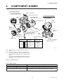
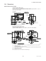
3.
COMPONENT NAMES
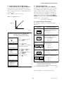
Vertical impulse piping type
Process connection
Pressure-detector section
Process connector (Note 1)
Cover
flange
Horizontal impulse piping type
External indicator
conduit connection (Note 1)
External indicator
conduit connection (Note 1)
Terminal box cover
Conduit
connection
CPU assembly
Integral
indicator (Note 1)
Conduit
connection
Mounting screw
Transmitter section
Range-setting
switch (Note 1)
(See Subsection 7.6)
Setting pin (CN4)
Cover
flange
Open to atmosphere
(∅5mm)
Amplifier Cover
Setting pin (CN4)
position (Note 2)
Zeroadjustment
screw
Burn - out
direction
Output at
burn - out
HIGH
110% or
higher
LOW
-5% or
lower
H
L
H
L
Process connection
Process connector (Note 1)
F0301.EPS
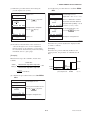
Note 1: See Subsection 10.2, “Model and Suffix Codes,” for
details.
Note 2: Insert the pin (CN4) as shown in the figure above to
set the burn-out direction. The pin is set to the H side
for delivery (unless option code /C1 is specified in the
order).
The setting can be confirmed by calling up parameter
D52 using the BRAIN TERMINAL. Refer to Subsection
8.3.3 (8).
Figure 3.1 Component Names
Table 3.1 Display Symbol
Display Symbol
Meaning of Display Symbol
The output signal being zero-adjusted is increasing.
The output signal being zero-adjusted is decreasing.
%, Pa, kPa, MPa, kgf/cm2, gf/cm2, mbar, bar,
atm, mmHg, mmH2O, inH2O, inHg, ftH2O, psi, Torr
Select one of these sixteen available engineering units for the display.
T0301.EPS
3-1
IM 01C21D01-01E
4. INSTALLATION
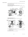
4.
INSTALLATION
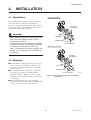
4.1 Precautions
Vertical pipe mounting
Before installing the transmitter, read the cautionary
notes in Section 2.4, “Selecting the Installation
Location.” For additional information on the ambient
conditions allowed at the installation location, refer to
Section 10.1 “Standard Specifications.”
Transmitter
mounting bolt
IMPORTANT
U-bolt nut
• When welding piping during construction, take
care not to allow welding currents to flow
through the transmitter.
• Do not step on this instrument after installation.
• For Model EJA430A, the atmospheric opening
is located on the low pressure side cover
flange. The opening must not face upward. See
Section 10.4, “Dimensions,” for the location of
the opening.
Mounting bracket
U-bolt
50 mm(2-inch) pipe
Horizontal pipe mounting
Transmitter
mounting bolt
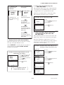
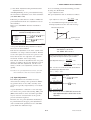
4.2 Mounting
The transmitter is shipped with the process connection, according to the ordering specifications. To
change the orientation of the process connections,
refer to Section 4.3.
The transmitter can be mounted on a nominal 50
mm (2-inch) pipe using the mounting bracket
supplied, as shown in Figure 4.2.1 and 4.2.2. The
transmitter can be mounted on either a horizontal or
a vertical pipe.
When mounting the bracket on the transmitter,
tighten the (four) bolts that hold the transmitter with
a torque of approximately 39 N·m {4kgf·m}.
U-bolt nut
Mounting bracket
U-bolt
50 mm(2-inch) pipe
F0401.EPS
Figure 4.2.1 Transmitter Mounting (Horizontal Impulse
Piping Type)
4-1
IM 01C21D01-01E
4. INSTALLATION
Vertical pipe mounting
(Process connector upside)
U-bolt nut
Transmitter
mounting bolt
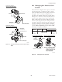
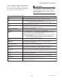
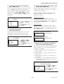
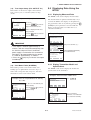
4.3 Changing the Process Connection
The transmitter is shipped with the process connection
specified at the time of ordering. To make a change
such as modifying the drain (vent) plug(s) attached to
the upside of the cover flange on shipment to be
attached to the downside follow the procedure below.
Mounting bracket
U-bolt
50 mm(2-inch) pipe
Vertical pipe mounting
(Process connector downside)
To begin, use a wrench to slowly and gently unscrew
the drain (vent) plug(s). Then, remove and remount
them on the opposite side. Wrap sealing tape around
the drain (vent) plug threads (*1 in the figure below),
and apply a lubricant to the threads of the drain (vent)
screw(s) (*2 below) to screw it (them) in. To tighten
the drain (vent) plugs, apply a torque of 34 to 39 N·m
{3.5 to 4 kgf·m}. Tighten the process connector bolts
uniformly to a torque shown below.
Transmitter
mounting bolt
Model
EJA310A
EJA430A
Mounting bracket
Torque(N·m)
{kgf·m}
U-bolt nut
EJA440A
C capsule D capsule
39 to 49 {4 to 5}
Vertical impulse piping type
49 to 59
{5 to 6}
Horizontal impulse piping type
U-bolt
Bolt
Process
connector
gasket
50 mm(2-inch) pipe
F0402.EPS
Figure 4.2.2 Transmitter Mounting (Vertical Impulse Piping
Type)
∗1
Drain/vent plug
∗2
Note: For a horizontal impulse
piping type, moving the
process connectors from
the front side to the
back is not allowed.
F0403.EPS
Figure 4.3
4-2
Changing Process Connection
IM 01C21D01-01E
4. INSTALLATION
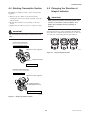
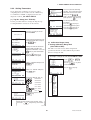
4.4 Rotating Transmitter Section
The DPharp transmitter section can be rotated in 90°
segments.
4.5 Changing the Direction of
Integral Indicator
1) Remove the two Allen screws that fasten the
transmitter section and capsule assembly, using the
Allen wrench.
2) Rotate the transmitter section slowly in 90° segments.
3) Tighten the two Allen screws to a torque of 5 N·m.
IMPORTANT
Do not rotate the transmitter section more than
180°.
IMPORTANT
Always turn OFF power, release pressure and
remove a transmitter to non-hazardous area
before disassembling and reassmbling an
indicator.
An integral indicator can be installed in the following
three directions. Follow the instructions in section 9.4
for removing and attaching the integral indicator.
Vertical impulse piping type
Pressure-detector section
Rotate 90° or 180° segments
F0405.EPS
Figure 4.5
Integral Indicator Direction
Conduit connection
Transmitter section
Horizontal impulse piping type
Transmitter section
Rotate 90° or 180° segments
Conduit connection
Zero-adjustment screw
Pressure-detector section
F0404.EPS
Figure 4.4
Rotating Transmitter Section
4-3
IM 01C21D01-01E
5. INSTALLING IMPULSE PIPING
5.
INSTALLING IMPULSE PIPING
5.1 Impulse Piping Installation
Precautions
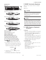
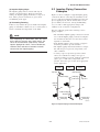
5.1.2 Routing the Impulse Piping
(1) Process Pressure Tap Angles
If condensate, gas, sediment or other extraneous
material in the process piping gets into the impulse
piping, pressure measurement errors may result. To
prevent such problems, the process pressure taps must
be angled as shown in Figure 5.1.2 according to the
kind of fluid being measured.
The impulse piping that connects the process outputs to
the transmitter must convey the process pressure
accurately. If, for example, gas collects in a liquidfilled impulse piping, or the drain of a gas-filled
impulse piping becomes plugged, the impulse piping
will not convey the pressure accurately. Since this will
cause errors in the measurement output, select the
proper piping method for the process fluid (gas, liquid,
or steam). Pay careful attention to the following points
when routing the impulse piping and connecting the
impulse piping to the transmitter.
NOTE
• If the process fluid is a gas, the taps must be
vertical or within 45° either side of vertical.
• If the process fluid is a liquid, the taps must be
horizontal or below horizontal, but not more
than 45° below horizontal.
• If the process fluid is steam or other condensing vapor, the taps must be horizontal or above
horizontal, but not more than 45° above horizontal.
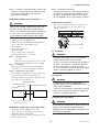
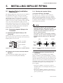
5.1.1 Connecting Impulse Piping to the
Transmitter
(1) Connecting the Impulse Piping to the
Transmitter
Symbols “H” and “L” are shown on a capsule assembly to indicate high and low pressure side. Connect the
impulse piping to the “H” side.
[Gas]
[Steam]
45° 45°
“H” and “L” are shown
Pressure
taps
Process connection
Process connector
Bolt
[Liquid]
Process
piping
45°
45°
45°
45°
F0502.EPS
F0501.EPS
Figure 5.1.1 “H” and “L” Symbols on a Capsule Assembly
Figure 5.1.2 Process Pressure Tap Angle (For Horizontal
Piping)
(2) Tightening the Process Connector Mounting Bolts
After connecting the impulse piping, tighten the
process connector mounting bolts uniformly.
(2) Position of Process Pressure Taps and
Transmitter
If condensate (or gas) accumulates in the impulse
piping, it should be removed periodically by opening
the drain (or vent) plugs. However, this will generate a
transient disturbance in the pressure measurement, and
therefore it is necessary to position the taps and route
the impulse piping so that any extraneous liquid or gas
generated in the leadlines returns naturally to the
process piping.
• If the process fluid is a gas, then as a rule the
transmitter must be located higher than the process
pressure taps.
• If the process fluid is a liquid or steam, then as a
rule the transmitter must be located lower than the
process pressure taps.
5-1
IM 01C21D01-01E
5. INSTALLING IMPULSE PIPING
(3) Impulse Piping Slope
The impulse piping must be routed with only an
upward or downward slope. Even for horizontal
routing, the impulse piping should have a slope of at
least 1/10 to prevent condensate (or gases) from
accumulating in the pipes.
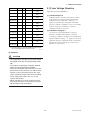
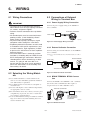
5.2 Impulse Piping Connection
Examples
Figure 5.2 shows examples of typical impulse piping
connections. Before connecting the transmitter to the
process, study the transmitter installation location, the
process piping layout, and the characteristics of the
process fluid (corrosiveness, toxicity, flammability,
etc.), in order to make appropriate changes and
additions to the connection configurations.
(4) Preventing Freezing
If there is any risk that the process fluid in the impulse
piping or transmitter could freeze, use a steam jacket or
heater to maintain the temperature of the fluid.
Note the following points when referring to these
piping examples.
• The transmitter impulse piping connection is shown
for a vertical impulse piping connection configuration in which the direction of connection is either
upwards or downwards.
• If the impulse piping is long, bracing or supports
should be provided to prevent vibration.
• The impulse piping material used must be compatible with the process pressure, temperature, and
other conditions.
• A variety of process pressure tap valves (main
valves) are available according to the type of
connection (flanged, screwed, welded), construction
(globe, gate, or ball valve), temperature and
pressure. Select the type of valve most appropriate
for the application.
NOTE
After completing the connections, close the valves
on the process pressure taps (main valves), the
valves at the transmitter (stop valves), and the
impulse piping drain valves, so that condensate,
sediment, dust and other extraneous material
cannot enter the impulse piping.
Liquid
Gas
Steam
Union or flange
Tap valve
Union or flange
Drain plug
Drain valve
Tap valve
Union or
flange
Tee
Tee
Tee
Union or flange
Tap valve
Drain valve
Drain valve
Drain plug
Drain plug
F0503.EPS
Figure 5.2 Impulse Piping Connection Examples
5-2
IM 01C21D01-01E
6. WIRING
6.
WIRING
6.1 Wiring Precautions
IMPORTANT
• Lay wiring as far as possible from electrical
noise sources such as large capacity transformers, motors, and power supplies.
• Remove electrical connection dust cap before
wiring.
• All threaded parts must be treated with waterproofing sealant. (A non-hardening silicone
group sealant is recommended.)
• To prevent noise pickup, do not pass signal
and power cables through the same ducts.
• Explosion-protected instruments must be wired
in accordance with specific requirements (and,
in certain countries, legal regulations) in order
to preserve the effectiveness of their explosionprotected features.
• The terminal box cover is locked by an Allen
head bolt (a shrouding bolt) on CENELEC and
IECEx flameproof type transmitters. When the
shrouding bolt is driven clockwise by an Allen
wrench, it is going in and cover lock is released, and then the cover can be opened by
hand. See Subsection 9.4 “Disassembly and
Reassembly” for details.
6.3 Connections of External
Wiring to Terminal Box
6.3.1 Power Supply Wiring Connection
Connect the power supply wiring to the SUPPLY +
and – terminals.
Transmitter terminal box
+
Power supply
–
F0601.EPS
Figure 6.3.1 Power Supply Wiring Connection
6.3.2 External Indicator Connection
Connect wiring for external indicators to the CHECK +
and – terminals.
(Note) Use a external indicator whose internal resistance is 10 Ω or
less.
External indicator
Power supply
+
–
Transmitter terminal box
6.2 Selecting the Wiring Materials
(a) Use stranded leadwires or cables which are the
same as or better than 600 V grade PVC insulated
wire (JIS C3307) or equivalent.
(b) Use shielded wires in areas that are susceptible to
electrical noise.
(c) In areas with higher or lower ambient temperatures,
use appropriate wires or cables.
(d) In environment where oils, solvents, corrosive gases
or liquids may be present, use wires or cables that
are resistant to such substances.
(e) It is recommended that crimp-on solderless terminal
lugs (for 4 mm screws) with insulating sleeves be
used for leadwire ends.
F0602.EPS
Figure 6.3.2 External Indicator Connection
6.3.3 BRAIN TERMINAL BT200 Connection
Connect the BT200 to the SUPPLY + and – terminals
(Use hooks). The communication line requires a
reception resistor of 250 to 600 Ω in series.
Transmitter terminal box
+
Power supply
–
BT200
Ignore the polarity
since the BT200 is
AC-coupled to the
terminal box.
F0603.EPS
Figure 6.3.3 BT200 Connection
6-1
IM 01C21D01-01E
6. WIRING
(2) Intrinsically Safe Type
For intrinsically safe type, a safety barrier must be
included in the loop.
6.3.4 Check Meter Connection
Connect the check meter to the CHECK + and –
terminals (use hooks).
• A 4 to 20 mA DC output signal from the CHECK +
and – terminals.
Hazardous Location
(Note) Use a check meter whose internal resistance is 10 Ω or less.
Transmitter terminal box
Nonhazardous Location
Distributor
(Power supply unit)
Power supply
+
Receiver
instrument
–
+
–
Check meter
Transmitter terminal box
F0604.EPS
Figure 6.3.4 Check Meter Connection
Safety barrier
Figure 6.4.1b Connection between Transmitter and
Distributor
6.4 Wiring
6.4.2 Wiring Installation
6.4.1 Loop Configuration
Since the DPharp uses a two-wire transmission system,
signal wiring is also used as power wiring.
DC power is required for the transmitter loop. The
transmitter and distributor are connected as shown
below.
For details of the power supply voltage and load
resistance, see Section 6.6; for communications line
requirements, see Subsection 8.1.2.
(1) General-use Type and Intrinsically Safe
Type
Make cable wiring using metallic conduit or waterproof glands.
• Apply a non-hardening sealant to the terminal box
connection port and to the threads on the flexible
metal conduit for waterproofing.
(1) General-use Type and Flameproof Type
Hazardous Location
Transmitter terminal box
F0606.EPS
Flexible metal conduit
Nonhazardous Location
Wiring metal
conduit
Distributor
(Power supply unit)
Apply a non-hardening
sealant to the threads for
waterproofing.
Tee
Drain plug
F0607.EPS
+
Receiver
instrument
Figure 6.4.2a Typical Wiring Using Flexible Metal Conduit
–
F0605.EPS
Figure 6.4.1a Connection between Transmitter and
Distributor
6-2
IM 01C21D01-01E
6. WIRING
(2) Flameproof Type
Wire cables through a flameproof packing adapter, or
using a flameproof metal conduit.
䊏 Wiring cable through flameproof packing adapter.
• Apply a nonhardening sealant to the terminal box
connection port and to the threads on the flameproof
packing adapter for waterproofing.
6.5 Grounding
Grounding is always required for the proper operation
of transmitters. Follow the domestic electrical requirements as regulated in each country. For a transmitter
with built-in lightning protector, grounding should
satisfy ground resistance of 10⍀ or less.
Ground terminals are located on the inside and outside
of the terminal box. Either of these terminals may be
used.
Flameproof packing adapter
Transmitter terminal box
Flexible metal conduit
Wiring metal
conduit
Apply a non-hardening
sealant to the threads for
waterproofing.
Ground terminal
(Inside)
Tee
Drain plug
F0608.EPS
Figure 6.4.2b Typical Cable Wiring Using Flameproof
Packing Adapter
䊏 Flameproof metal conduit wiring
• A seal fitting must be installed near the terminal box
connection port for a sealed construction.
• Apply a non-hardening sealant to the threads of the
terminal box connection port, flexible metal conduit
and seal fitting for waterproofing.
Ground terminal
(Outside)
Figure 6.5 Ground Terminals
6.6 Power Supply Voltage and
Load Resistance
Gas sealing device
Non-hazardous area
Flameproof flexible
metal conduit
When configuring the loop, make sure that the external
load resistance is within the range in the figure below.
Hazardous area
Flameproof
heavy-gauge
steel conduit
Apply a non-hardening
sealant to the threads of
these fittings for
waterproofing
(Note) In case of an intrinsically safe transmitter, external load
resistance includes safety barrier resistance.
600
Tee
Drain plug
;;
F0610.EPS
Seal fitting
After wiring, impregnate the fitting
with a compound to seal tubing.
External
load
resistance
R (Ω)
F0609.EPS
Figure 6.4.2c Typical Wiring Using Flameproof Metal
Conduit
250
R=
0
E–10.5
0.0236
10.5
Communication
applicable range
BRAIN and HART
16.4
24.7
42
Power supply voltage E (V DC)
F0611.EPS
Figure 6.6 Relationship between Power Supply Voltage
and External Load Resistance
6-3
IM 01C21D01-01E
7. OPERATION
7.
OPERATION
7.1 Preparation for Starting
Operation
The Model EJA310A, EJA430A and EJA440A
pressure transmitter measures the pressure of liquids,
gases, and steam. This section describes the operation
procedure for the EJA430A as shown in Figure 7.1
(vertical impulse piping type, high-pressure connection:
right side) when measuring a pressure.
Vent plug (Fill plug)
Tap valve
Stop valve
NOTE
Confirm that the process pressure tap valve,
drain valve, and stop valve are closed.
(a) Introduce a process fluid into the impulse piping
and then to the transmitter in the following procedure:
1) Open the tap valve (main valve) to fill the impulse
piping with process fluid.
2) Gradually open the stop valve to introduce process
fluid into the transmitter pressure-detector section.
3) Confirm that there is no pressure leak in the
impulse piping, transmitter, or other components.
Drain valve
F0701.EPS
Figure 7.1 Liquid Flow Measurement
Confirming that Transmitter is Operating
Properly
Using the BT200
• If the wiring system is faulty, ‘communication error’
appears on the display.
• If the transmitter is faulty, ‘SELF CHECK ERROR’
appears on the display.
(b) Venting Gas from the Transmitter Pressure-detector
Section
Since the piping in the example of Figure 7.1 is
constructed to be self-venting, no venting operation
is required. If it is not possible to make the piping
self-venting, refer to Subsection 7.5 for instructions.
(c) Turn ON power and connect the BT200.
Open the terminal box cover, and connect the
BT200 to the SUPPLY + and – terminals.
(d) Using the BT200, confirm that the transmitter is
operating properly. Check parameter values or
change the setpoints as necessary. See Chapter 8 for
BT200 operation.
If the transmitter is equipped with an integral
indicator, its indication can be used to confirm that
the transmitter is operating properly.
PARAM
C60:SELF CHECK
ERROR
communication error
DATA
Communication error
(Faulty wiring)
DIAG
PRNT
ESC
Self-diagnostic error
(Faulty transmitter)
F0702.EPS
7-1
IM 01C21D01-01E
7. OPERATION
Using the integral indicator
• If the wiring system is faulty, the display stays blank.
• If the transmitter is faulty, an error code will appear
on the display according to the nature of the error.
7.2 Zero Point Adjustment
Adjust the zero point after operating preparation is
completed.
IMPORTANT
Do not turn off the power to the transmitter
immediately after a zero adjustment. Powering
off within 30 seconds after a zero adjustment will
return the adjustment back to the previous
settings.
Self-diagnostic error on
the integral indicator
(Faulty transmitter)
F0703.EPS
The zero point adjustment can be made in either way:
using the zero-adjustment screw of the transmitter or
the BT200 operation.
NOTE
If any of the error indications above appears on
the display of the integral indicator or BT200,
refer to Subsection 8.5.2 for corrective action.
For output signal checking, display the parameter A10:
OUTPUT (%) in the BT200.
Verify and Change Transmitter Parameter
Setting and Values
The following parameters are the minimum settings
required for operation. The transmitter has been
shipped with these parameters. To confirm or change
the values, see Subsection 8.3.3.
BT200
Output signal (%)
display
PARAM
A10:OUTPUT(%)
0.0 %
A11:ENGR OUTPUT
A20:AMP TEMP
• Measuring range..........See Subsection 8.3.3 (2)
• Operation mode...........See Subsection 8.3.3 (7)
DATA
DIAG
PRNT
ESC
Zero-adjustment Screw
Zero-adjustment
screw
F0704.EPS
After reviewing this parameter you are prepared to
adjust the zero point. When making the zero adjustment on a pressure transmitter, the process pressure
value does not have to be set to the low limit of the
measurement range (0%). In such case, adjust the
transmitter output signal to the actual measured value
obtained from a high-accuracy pressure measuring
instrument.
7-2
IM 01C21D01-01E
7. OPERATION
7.2.1 When you can obtain Low Range
Value from actual measured value
of 0% (0 kPa, atmospheric pressure);
7.2.2 When you cannot obtain Low Range
Value from actual measured value
of 0%;
Convert the actual measured value obtained by a digital
manometer or a glass gauge into %.
For pressure measurement using gauge pressure
transmitters, follow the step below before zero point
adjustment.
1) Close the tap valve (main valve).
2) Loosen the fill plug so that the pressure applied to
the transmitter is only the head of the seal liquid.
3) Adjust the zero point at this status.
4) After the adjustment, close the fill plug and then
gradually open the tap valve.
[Example]
The measuring range of 50 to 250 kPa; the actual
measured value of 130 kPa.
Actual measured value=
x 100=40.0%
Using the Transmitter Zero-Adjustment Screw
Turn the screw to match the output signal to the actual
measured value in %.
Using the Transmitter Zero-adjustment
Screw
Before adjusting a screw, check that the parameter
J20: EXT ZERO ADJ displays ENABLE. See
Subsection 8.3.3 (11) for the setting procedure.
Using the BT200
Select the parameter J10: ZERO ADJ. Change the
set point (%) displayed for the parameter to the actual
measured value (%), and press the ENTER key twice.
See Subsection 8.3.3 (11) for operation details.
Use a slotted screwdriver to turn the zero-adjustment
screw. Turn the screw clockwise to increase the output
or counterclockwise to decrease the output. The zero
point adjustment can be made with a resolution of
0.01% of the setting range. Since the degree of zero
adjustments varies with the screw turning speed, turn
the screw slowly for fine adjustment and quickly for
coarse adjustment.
A display at J10
SET
J10:ZERO ADJ
–0.0 %
+ 000.0
CLR
ESC
Change setting to the actually
SET
J10:ZERO ADJ
–0.0 %
+ 040.0
Using the BT200
Zero point can be adjusted by simple key operation of
the BT200.
measured value (40.0%).
Press
key twice
for 40% output 10.4 mA DC.
Select parameter J10: ZERO ADJ, and press the
ENTER key twice. The zero point will be adjusted
automatically to the output signal 0% (4 mA DC).
Confirm that the setting value displayed for the
parameter is ‘0.0%’ before pressing the ENTER key.
See Subsection 8.3.3 (11) for BT200 operating procedures.
SET
J10:ZERO ADJ
–0.0 %
+ 000.0
130–50
250–50
CLR
ESC
F0706.EPS
A display when parameter
J10 is selected.
Press
key
twice for 0% output 4 mA DC.
CLR
ESC
F0705.EPS
7-3
IM 01C21D01-01E
7. OPERATION
7.3 Starting Operation
7.5 Venting or Draining Transmitter Pressure-detector Section
After completing the zero point adjustment, follow the
procedure below to start operation.
Since this transmitter is designed to be self-draining
and self-venting with vertical impulse piping connections, neither draining nor venting will be required if
the impulse piping is configured appropriately for selfdraining or self-venting operation.
1) Confirm the operating status. If the output signal
exhibits wide fluctuations (hunting) due to periodic
variation in the process pressure, use BT200 to
dampen the transmitter output signal. Confirm the
hunting using a receiving instrument or the integral
indicator, and set the optimum damping time
constant. See Subsection 8.3.3 (3), “Damping Time
Constant Setup.”
2) After confirming the operating status, perform the
following.
If condensate (or gas) collects in the transmitter
pressure-detector section, the measured pressure may
be in error. If it is not possible to configure the piping
for self-draining (or self-venting) operation, you will
need to loosen the drain (vent) screw on the transmitter
to completely drain (vent) any stagnated liquid (gas).
However, since draining condensate or bleeding off gas
gives the pressure measurement disturbance, this
should not be done when the loop is in operation.
IMPORTANT
• Remove the BT200 from the terminal box, and
confirm that none of the terminal screws are
loosened.
• Close the terminal box cover and the amplifier
cover. Screw each cover in tightly until it will
not turn further.
• Two covers are required to be locked on the
CENELEC and IECEx Flameproof type transmitters. An Allen head bolts (shrouding bolts)
are provided under edge of the each cover for
locking. When a shrouding bolts are driven
counterclockwise by an Allen wrench, it is
coming out and locks up a cover. (See page 93) After locking, the covers should be confirmed not to be opened by hand.
• Tighten the zero-adjustment cover mounting
screw to fix the cover in position.
WARNING
Since the accumulated liquid (or gas) may be
toxic or otherwise harmful, take appropriate care
to avoid contact with the body, or inhalation of
vapors.
7.5.1 Draining Condensate
1) Gradually open the drain screw or drain plug and
drain the transmitter pressure-detector section. (See
Figure 7.5.1.)
2) When all accumulated liquid is completely removed, close the drain screw or drain plug.
3) Tighten the drain screw to a torque of 10 N·m, and
the drain plug to a torque of 34 to 39 N·m.
7.4 Shutting Down Operation
Shut down the transmitter operation as follows.
1) Turn off the power.
2) Close the stop valve.
3) Close the tap valve.
NOTE
Drain plug
Whenever shutting down the transmitter for a
long period, remove any process fluid from the
transmitter pressure-detector section.
Drain screw
When you loosen the drain screw or drain
plug, the accumulated liquid will be expelled
in the direction of the arrow.
F0707.EPS
Figure 7.5.1 Draining the Transmitter
7-4
IM 01C21D01-01E
7. OPERATION
7.5.2 Venting Gas
6) Press the range-setting push-button. The integral
indicator then displays “HSET.”
7) Apply a pressure of 3 MPa to the transmitter. (Note 1)
8) Turn the external zero-adjustment screw in the
desired direction. The integral indicator displays the
output signal in %. (Note 2)
9) Adjust the output signal to 100% (5 V DC) by
rotating the external zero-adjustment screw. Doing
so completes the HRV setting.
10) Press the range-setting push-button. The transmitter
then switches back to the normal operation mode
with the measurement range of 0 to 3 MPa.
1) Gradually open the vent screw to vent gas from the
transmitter pressur-detector section. (See Figure
7.5.2.)
2) When the transmitter is completely vented, close
the vent screw.
3) Tighen the vent screw to a torque of 10 N·m.
Vent screw
Note 1: Wait until the pressure inside the pressure-detector section
has stabilized before proceeding to the next step.
Note 2: If the pressure applied to the transmitter exceeds the previous
LRV (or HRV), the integral indicator may display error
number “Er.07” (In this case, the output signal percent and
“Er.07” are displayed alternately every two seconds).
Although “Er.07” is displayed, you may proceed to the next
step. However, should any other error number be displayed,
take the appropriate measure in reference to Subsection
8.5.2, “Errors and Countermeasures.”
Vent screw
When you loosen the vent screw, the gas
escpes in the direction of the arrow.
F0708.EPS
Figure 7.5.2 Venting the Transmitter
IMPORTANT
7.6 Setting the Range Using the
Range-setting Switch
• Do not turn off the power to the transmitter
immediately after completion of the change in
the LRV and/or HRV setting(s). Note that
powering off within thirty seconds after setting
will cause a return to the previous settings.
• Changing LRV automatically changes HRV to
the following value.
With actual pressure being applied to the transmitter,
the range-setting switch (push-button) located on the
optional integral indicator plate and the external zeroadjustment screw allow users to change (re-range) the
low- and high-limit values for the measurement range
(LRV and HRV) without using BT200. However, other
changes in the display settings (scale range and
engineering unit) for the integral indicator requires
BT200.
HRV = previous HRV + (new LRV – previous LRV)
• If the range-setting push-button and external
zero-adjustment screw are not touched during a
range-change operation, the transmitter automatically switches back to the normal operation
mode.
Follow the procedure below to change the LRV and
HRV settings.
[Example]
Integral indicator
Rerange LRV to 0 and HRV to 3 MPa.
1) Connect the transmitter and apparatus as shown in
Figure 9.3.1 and warm up for at least five minutes.
2) Press the range-setting push-button.
The integral indicator then displays “LSET.”
3) Apply a pressure of 0 kPa (atmospheric pressure) to
the transmitter. (Note 1)
4) Turn the external zero-adjustment screw in the
desired direction. The integral indicator displays the
output signal in %. (Note 2)
5) Adjust the output signal to 0% (1 V DC) by rotating
the external zero-adjustment screw. Doing so
completes the LRV setting.
Note : Use a thin bar which
has a blunt tip, e.g.,
a hexagonal wrench,
to press the rangesetting push-button
Range-setting switch
(Push-button)
F0709.EPS
Figure 7.6 Range-setting Switch
7-5
IM 01C21D01-01E
8. BRAIN TERMINAL BT200 OPERATION
8.
BRAIN TERMINAL BT200
OPERATION
The DPharp is equipped with BRAIN communications capabilities, so that range changes, Tag No.
setup, monitoring of self-diagnostic results, and zero
point adjustment can be handled by remote control
via BT200 BRAIN TERMINAL or CENTUM CS
console. This section describes procedures for setting
parameters using the BT200. For details concerning
the BT200, see IM 01C00A11-01E, “BT200 User’s
Manual.”
8.2 BT200 Operating Procedures
8.2.1 Key Layout and Screen Display
Figure 8.2.1a shows the arrangement of the operating
keys on the BT200 keypad, and Figure 8.2.1b shows
the BT200 screen component.
LCD
(21 character × 8 lines)
8.1 BT200 Operation Precautions
8.1.1 Connecting the BT200
The transmitter and the BT200 can be connected
either to the BT200 connection hooks in the transmitter terminal box or to a relaying terminal board.
Function keys
Movement keys
ENTER key
Relaying
terminals
Control room
Power ON/OFF key
Terminal board
Alphanumeric keys
Distributor
Shift keys
F0801.EPS
F0803.EPS
Figure 8.2.1a BT200 Key Layout
Figure 8.1.1 Connecting the BT200
MENU SCREEN
8.1.2 Conditions of Communication Line
MENU
A:DISPLAY
B:SENSOR TYPE
Screen title
HOME
Parameters
Cable
resistance Rc
SET
ADJ
ESC
PARAMETER SCREEN
cc
Load
resistance R
Messages
Menu choices
Cable resistance Rc
Power
supply
BATTERY
DPharp
PARAM
A10:OUTPUT
100.0 %
A11:ENGR. OUTPUT
1000 mmH20
A20:AMP TEMP
23 deg C
DATA
DI
AG
Function
commands
PRNT
F0804.EPS
Loop resistance = R + 2Rc
= 250 to 600 Ω
Loop capacitance = 0.22 µF max.
Figure 8.2.1b BT200 Screen Component
BT200
F0802.EPS
Figure 8.1.2 Conditions of Communication Line
8-1
IM 01C21D01-01E
8. BRAIN TERMINAL BT200 OPERATION
8.2.2 Operating Key Functions
(1) Alphanumeric Keys and Shift Keys
You can use the alphanumeric keys in conjunction
with the shift keys to enter symbols, as well as
alphanumeric keys.
Use the function key [F1] CODE to enter symbols.
The following symbols will appear in sequence, one
at a time, at the cursor each time you press [F1]
CODE:
/ . – , + * ) ( ’ & % $ # ” !
To enter characters next to these symbols, press [ > ]
to move the cursor.
Entry
Key-in Sequence
Alphanumeric keys
symbol command
l/m
(I)
(m)
(/)
T0803.EPS
Shift keys
F0805.EPS
(2) Function Keys
The functions of the function keys depend on the
function commands on display.
a. Entering Digits, Symbols, and Spaces
Simply press the alphanumeric keys.
Entry
Key-in Sequence
MENU
A:DISPLAY
B:SENSOR TYPE
–4
0.3
1
–9
HOME
SET
ADJ
ESC
Function commands
T0801.EPS
b. Entering Letters (A through Z)
Press an alphanumeric key following a shift key to
enter the letter shown on that side which the shift key
represents. You must press the shift key before
entering each letter.
Function keys
F0808.EPS
Function Command List
Command
Left-side letter on the
alphanumeric key
ADJ
Right-side letter on
the alphanumeric key
CAPS/caps Selects uppercase or lowercase
CODE
F0806 .EPS
Entry
Key-in Sequence
W
IC
J. B
T0802.EPS
Use the function key [F2] CAPS to select between
uppercase and lowercase (for letters only). The case
toggles between uppercase and lowercase each time
you press [F2] CAPS.
CODE
CAPS
CLR
Erases input data or deletes all data
Updates parameter data
DEL
Deletes one character
DIAG
Calls the self-check panel
ESC
Returns to the most recent display
CLR
ESC
Entry
CODE
caps
CLR
Quits setup and returns to the previous display
OK
Proceeds to the next panel
SET
ESC
Displays the SET menu
SLOT
Returns to the slot selection panel
UTIL
Calls the utility panel
*COPY
Prints out parameters on display
*FEED
Paper feed
*LIST
Lists all parameters in the menu
*PRNT
to lower case
Boy
*GO
(o)
Enters the parameter number setup mode
*PON/POFF Automatic printout mode on or off
Key-in Sequence
(B)
Displays the menu panel
NO
PARM
Entering lowercase
Selects symbols
DATA
HOME
Entering uppercase
Function
Displays the ADJ menu
(y)
*STOP
F0807.EPS
Changes to the print mode
Starts printing
Cancels printing
* Available on BT200-P00 (with printer).
T0804.EPS
8-2
IM 01C21D01-01E
8. BRAIN TERMINAL BT200 OPERATION
8.2.3 Calling Up Menu Addresses Using the Operating Keys
––WELCOME––
BRAIN TERMINAL
ID: BT200
STARTUP
SCREEN check connection
push ENTER key
UTIL
The utility screen contains the
following items.
1. BT200 ID settings
2. Security code settings
3. Switching language of messages
(Japanese or English)
4. LCD contrast setting
5. Adjusting printout tone
(BT200-P00 only)
UTILITY
1.ID
2.SECURITY CODE
3.LANGUAGE SELECT
4.LCD CONTRAST
5.PRINTER ADJUST
esc
FEED
(UTIL)
INITIAL
DATA
SCREEN
PARAM
01:MODEL
EJA430A-DA
02:TAG NO.
YOKOGAWA
03:SELF CHECK
GOOD
FUNC
1.MENU
2.UPLOAD TO BT200
3.DOWNLOAD TO INST
4.PRINT ALL DATA
(ESC)
OK
HOME
(SET MENU SCREEN)
MENU
A.DISPLAY
B.SENSOR TYPE
PARAMETER
SCREEN
SETUP
SCREEN
SET
ADJ
ESC
HOME
SET
MENU
J.ADJUST
K.TEST
M.MEMO
P:RECORD
ADJ
ESC
PARAM
A60:SELF CHECK
GOOD
PARAM
C60:SELF CHECK
GOOD
PARAM
A21:CAPSULE TEMP
26.5 deg C
DATA DIAG PRNT
PARAM
C22:HIGH RANGE
100 kPa
DATA DIAG PRNT
ESC
PARAM
A10:OUTPUT(%)
50.0 %
DATA DIAG
PRNT
ESC
A11:ENGR,
OUTPUT
20.0 M
A20:AMP TEMP
24.5 deg C
DATA DIAG PRNT
ESC
CAPS
HOME
ESC
PARAM
C10:TAG NO.
YOKOGAWA
DATA DIAG
ESC
C20:PRESS
UNITPRNT
kPa
C21:LOW RANGE
0 kPa
DATA DIAG PRNT
ESC
SET
ADJ
ESC
PARAM
J60:SELF CHECK
GOOD
PARAM
J10:ZERO ADJ
0.0 %
DATA DIAG
ESC
J11:ZERO
DEV PRNT
22.2 %
J20:EXT. ZERO ADJ
ENABLE
DATA DIAG PRNT
ESC
See “BT200 Instruction Manual” for details
concerning uploading and downloading parameters
and printouts (BT200-P00).
SET
C10:TAG NO.
YOKOGAWA
YOKOGAWA
CODE
ESC
(ADJ MENU SCREEN)
MENU
C.SETTING
D.AUX SET 1
E.AUX SET 2
H:AUTO SET
MENU
SCREEN
HOME
ADJ
(ADJ)
(SET)
(HOME MENU SCREEN)
SET
CLR
ESC
F0809.EPS
8-3
IM 01C21D01-01E
8. BRAIN TERMINAL BT200 OPERATION
8.3 Setting Parameters Using the BT200
8.3.1 Parameter Summary
Instruments to which applicable:
F: Differential pressure transmitters
P: Pressure transmitters
L: Liquid level transmitters
No.
Item
01 MODEL
02 TAG NO.
EJA110A, EJA120A, and EJA130A
EJA310A, EJA430A, EJA440A, EJA510A, and EJA530A
EJA210A and EJA220A
Description
Model+capsule type
Tag number
03 SELF CHECK Self-diagnostic result
A
DISPLAY
Measured data display
A10 OUTPUT (%)
A11 ENGR.
OUTPUT
A20 AMP TEMP
A21 CAPSULE
TEMP
A30 STATIC
PRESS
A40 INPUT
Output (in %)
Output (in engineering
units)
Amplifier temperature
Capsule temperature
Static pressure
Input (indicated as the
value after zeroing)
A60 SELF CHECK Self-diagnostic
messages
B
B10
B11
B20
B21
B30
B40
SENSOR
TYPE
Sensor type
MODEL
STYLE NO.
LRL
URL
MIN SPAN
MAX STAT.P.
Model+span
Style number
Lower range-limit
Upper range-limit
Minimum span
Maximum static
pressure*6
B60 SELF CHECK Self-diagnostic
messages
C SETTING
Setting data
C10 TAG. NO.
Tag number
C20 PRESS UNIT Measurement range
units
Rewritability
D
AUX SET 1
Auxiliary setting data 1
F P L
—
16 alphanumerics
—
GOOD/ERROR
—
—
—
Menu name
–5 to 110%*3
–19999 to 19999
—
Unit specified in D30
Unit specified in D30
—
Unit specified in D31*1
—
–32000 to 32000
—
—
—
GOOD/ERROR, CAP MODULE FAULT, AMP MODULE FAULT,
OUT OF RANGE, OUT OF SP RANGE*1, OVER TEMP (CAP),
OVER TEMP (AMP), OVER OUTPUT, OVER DISPLAY,
ILLEGAL LRV, ILLEGAL HRV, ILLEGAL SPAN, and
ZERO ADJ OVER
—
Menu name
—
16 uppercase alphanumerics
—
—
—
—
–32000 to 32000
–32000 to 32000
–32000 to 32000
—
—
—
Same as A60
—
Menu name
—
16 alphanumerics
Selected from mmH2O, mmAq,
mmWG, mmHg, Torr, Pa, hPa, kPa,
MPa, mbar, bar, gf/cm2, kgf/cm2,
inH2O, inHg, ftH2O, psi, or atm
–32000 to 32000(but within
measurement range)
–32000 to 32000(but within
measurement range)
Selected from 0.2*2, 0.5, 1.0, 2.0,
4.0, 8.0, 16.0, 32.0, or 64.0 sec.
Selected from OUT:LIN; DSP:LIN,
OUT:LIN; DSP:SQR,
OUT:SQR; DSP:SQR
Same as A60
—
Menu name
As specified when ordered.
As specified when ordered.
As specified when ordered.
As specified when ordered.
2.0 s
As specified when ordered.
If not specified,
OUT: LIN; DSP: LIN.
D10 LOW CUT
D11 LOW CUT
MODE
D15 OUT LIMIT(L)
D16 OUT LIMIT(H)
D20 DISP SELECT
Low cut
Low cut mode
0.0 to 20.0%
LINEAR/ZERO
Lower output range-limit
Upper output range-limit
Display selection
–5.0%*1
110.0%
As specified when ordered.
D21 DISP UNIT
Engineering unit for
display
Engineering range,
lower range value
Engineering range,
higher range value
Temperature setting
units
–5.0 to 110.0%
–5.0 to 110.0%
NORMAL %/USER SET,
USER & %/INP PRES, PRES & %
8 uppercase
alphanumerics
–19999 to 19999
–19999 to 19999
As specified when ordered.
deg C/deg F
deg C
D22 DISP LRV
D23 DISP HRV
D30 TEMP UNIT
Applicability
Default Value
—
C21 LOW RANGE Measurement range,
lower range value
C22 HIGH
Measurement range,
RANGE
higher range value
C30 AMP
Damping time constant
DAMPING
C40 OUTPUT
Output mode and
integral indicator mode
MODE
C60 SELF CHECK Self-diagnostic
messages
Remarks
—
—
10.0%
LINEAR
As specified when ordered.
*1: Unless otherwise specified by order. When optional code /F1 is specified, substitute the value –5 with –2.5.
T0805.EPS
8-4
IM 01C21D01-01E
8. BRAIN TERMINAL BT200 OPERATION
No.
D
Item
AUX SET 1
D31 STAT. P. UNIT
Description
Auxiliary setting data 1
Auxiliary setting data 2
DFS mode
Reference temperature
sensor
Zero shift
conpensation setup
Bidirectional mode
E30 BI DIRE
MODE
E50 AUTO
Auto-recover from
RECOVER
sensor error
E60 SELF CHECK Self-diagnostic
messages
H
AUTO SET
—
Automatic setup
Automatic measurement range lower
range value setup
H11 AUTO HRV
Automatic
measurement range
higher range value
setup
H60 SELF CHECK Self-diagnostic
messages
ADJUST
Adjustment data
Automatic zero
adjustment
J11 ZERO DEV.
Manual zero
adjustment
J15 SPAN ADJ
Manual span adjustment
J20 EXT. ZERO
External zeroADJ
adjustment screw
permission
J30 OUTPUT 4mA 4mA adjustment
J31 OUTPUT 20mA 20mA adjustment
J60 SELF CHECK Self-diagnostic
messages
TEST
Tests
—
—
HOLD/HIGH/LOW, –5 to 110%*3
Same as A60
HIGH
HIGH
—
MEMO
Memo
M10
M20
M30
M40
M50
M60
M
MEMO 1
MEMO 2
MEMO 3
MEMO 4
MEMO 5
SELF CHECK
Memo
Memo
Memo
Memo
Memo
Self-diagnostic
messages
P
P10
P11
P12
P13
P60
RECORD
ERROR REC 1
ERROR REC 2
ERROR REC 3
ERROR REC 4
SELF CHECK
If not specified, NORMAL.
NORMAL
Menu name
OFF/ON*5
AMP. TEMP/CAP. TEMP*5
ON
CAP. TEMP
10.00*5
0.00
OFF/ON
OFF
OFF/ON
ON
—
Same as A60
—
Menu name
–32000 to 32000
Displays the same data as
C21.
–32000 to 32000
Displays the same data as
C22.
—
Same as A60
—
Menu name
—
—
—
—
—
—
—
—
–5 to 110.0%*3
–10.00 to 10.00%
ENABLE/INHIBIT
0.00%
0.00%
0.00%
—
–10.00 to 10.00%
–10.00 to 10.00%
Same as A60
—
Menu name
—
–5 to 110.0%*3 Displays ‘ACTIVE’
while executing
Same as A60
—
Menu name
—
8 uppercase alphanumerics
8 uppercase alphanumerics
8 uppercase alphanumerics
8 uppercase alphanumerics
8 uppercase alphanumerics
Same as A60
K10 OUTPUT in % Test output % setting
K60 SELF CHECK Self-diagnostic
messages
F P L
Menu name
HIGH/LOW, –5 to 110%*3
J10 ZERO ADJ
K
Applicability
Default Value
As specified when ordered.
If not specified, MPa.
H10 AUTO LRV
J
Remarks
Selected from mmH2O, mmAq,
mmWG, mmHg, Torr, Pa, hPa, kPa,
MPa, mbar, bar, gf/cm2, kgf/cm2,
inH2O, inHg, ftH2O, psi, or atm
NORMAL/REVERSE
NORMAL/REVERSE*4
Static pressure setting
units
D40 REV OUTPUT Output reversal
D45 H/L SWAP
Impulse piping
accessing direction
D52 BURN OUT
CPU error
D53 ERROR OUT Hardware error
D60 SELF CHECK Self-diagnostic
messages
E AUX SET 2
E10 DFS MODE
E14 TEMP
SELECT
E15 TEMP ZERO
Rewritability
History of the errors
—
Last error
Display the error
One time before
Display the error
Two time before
Display the error
Three time before
Display the error
Self-diagnostic
Same as A60
—
messages
*1: In case of Model EJA120A, static pressure cannot be measured. The display is always 0 MPa, but this is not a measured value.
*2: When Optional code /F1 is specified, substitute the value with 0.1.
*3: When Optional code /F1 is specified, substitute the value –5 with –2.5.
*4: Not applicable for Model EJA115.
*5: Applicable only for Model EJA118W, EJA118N, EJA118Y, EJA438W, and EJA438N.
*6: See MWP(max. working pressure) on the nameplate. B40 shows an approximate value of maximum pressure for the capsule.
T0806.EPS
8-5
IM 01C21D01-01E
8. BRAIN TERMINAL BT200 OPERATION
8.3.2 Parameter Usage and Selection
IMPORTANT
Before describing the procedure for setting parameters, we present the following table showing how
the parameters are used and in what case.
If the transmitter is turned off within 30 seconds
after parameters have been set, the set data
will not be stored and the terminal returns to
previous settings.
Table 8.3.1 Parameter Usage and Selection
Setup Item
Tag No. setup
P.8-7
Calibration range setup
P.8-7
Description
Sets the Tag No. (using 16 alphanumeric characters).
Note: Up to 8 alphanumerics (upper case letters) can be used in the BT100.
Sets the calibration range for 4 to 20 mA DC. Sets three data items: range unit, input value
at 4 mA DC (LRV), and input value at 20 mA DC (HRV).
Note: LRV and HRV can be specified with range value specifications up to 5 digits
(excluding any decimal point) within the range of –32000 to 32000.
Damping time constant setup
P.8-8
Output signal low cut mode setup
P.8-9
Adjusts the output response speed for 4 to 20 mA DC.
Can be set in 9 increments from 0.2 to 64 s.
Used mainly to stabilize output near 0% if output signal is the square root mode.
Two modes are available: forcing output to 0% for input below a specific value, or changing
to proportional output for input below a specific value.
Change the output limits
P.8-9
Integral indicator scale range and
unit setup
P.8-9
Change the range of normal output.
Sets the following 5 types of integral indicator scale ranges and units:
% scale indicator, user set scale indicator, alternate indication of user set scale
and % scale, input pressure display, alternate indication of input pressure and % scale
When using the user set scale, 4 types of data can be set:
user set scale setting, unit (BT200 only), display value at 4 mA DC (LRV), and display
value at 20 mA DC (HRV).
Note: LRV and HRV can be specified with range value specifications up to 5
digits (excluding any decimal point) within the range of –19999 to 19999.
Unit setup for displayed temperature
P.8-11
Sets a unit for temperatures displayed on the BT200.
Operation mode (normal/reverse
signal) setup
P.8-11
Reverses the direction for 4 to 20 mA DC output relative to input.
Reverse mode is used for applications in which safety requires that output be
driven toward 20 mA if input is lost.
Output status display/setup when
a CPU failure P.8-11
Displays the status of 4 to 20 mA DC output when a CPU failure. The parameter
of the standard unit is fixed to the high limit value.
Output status setup when a hardware Sets the status of the 4 to 20 mA DC output when an abnormal status is detected
error occurs
with the capsule or the amplifier as the result of self-diagnosis. One of the
P.8-11
following statuses; last held, high limit, and low limit values, can be selected.
Range change (while applying
actual inputs)
P.8-12
Range for 4 to 20 mA DC signal is set with actual input applied. Sets 20 mA DC output
precisely with respect to user’s reference instrument output. Note that DPharp is calibrated
with high accuracy before shipment, so span should be set using the normal range setup.
Zero point adjustment
P.8-12
Adjusts zero point. This can be done either using the external zero-adjustment screw on
the transmitteror using the BT200.
Span adjustment
P.8-14
Adjust the characterization curve. All the transmitters are calibrated at factory and this
adjustment is normally not necessary for most cases. Use for specific purposes.
Test output (fixed current output)
setup P.8-15
Used for loop checks.
Output can be set freely from –5% to 110% in 1% steps.
User memo fields
P.8-15
Allows user to enter up to 5 items of any desired text in up to 8 uppercase
alphanumeric characters per item.
T0807.EPS
8-6
IM 01C21D01-01E
8. BRAIN TERMINAL BT200 OPERATION
8.3.3 Setting Parameters
Set or change the parameters as necessary. After
completing these, do not fail to use the “DIAG” key
to confirm that “GOOD” is displayed for the selfdiagnostic result at _60: SELF CHECK.
set data. The set data items flash.
When all items have been confir-
PRINTER OFF
F2:PRINTER ON
FEED POFF
NO
med, press the
again. (To go back to the setting
panel, press the
(NO) key.
(1) Tag No. Setup (C10: TAG NO)
Use the procedure below to change the Tag No. Up
to 16 alphanumeric characters can be entered.
The DPharp TAG NO. was
SET
C10:TAG NO.
FIC-1a
FEED
overwritten.
Press the
NO
PARAM
C10:TAG NO.
FIC-1a
C20:PRESS UNIT
kPa
C21:LOW RANGE
0 kPa
DATA DIAG PRNT
• Example: Set a Tag No. to FIC-1a
Press the
the BT200.
This is the panel for confirming
SET
C10:TAG NO.
YOKOGAWA
FIC-1a
key to turn on
<When power is off>
OK
(OK) key to
return to the parameter panel.
Press the
(NO) key to
return to the setting panel.
ESC
F0811.EPS
––WELCOME––
BRAIN TERMINAL
ID: BT200
Connect DPharp and BT200 using
a communication cable and press
the
key.
check connection
push ENTER key
UTIL
FEED
Displays the name of connected
DPharp model, TAG NO. and
diagnostics information. Press the
(OK) key after confirmation.
PARAM
01:MODEL
EJA430A-DA
02:TAG NO.
YOKOGAWA
03:SELF CHECK
GOOD
OK
MENU
A:DISPLAY
B:SENSOR TYPE
HOME
SET
ADJ
SET
a. Setting Calibration Range Unit
(C20: PRESS UNIT)
The unit is set at the factory before shipment if
specified at the time of order. Follow the procedure
below to change the unit.
Press the
(SET) key to
display the SET menu panel.
• Example: Change the unit from mmH2O to kPa.
SET
C20:PRESS UNIT
mmH20
< mmWG >
< mmHG >
< Torr >
< kPa >
ESC
MENU
C:SETTING
D:AUX SET 1
E:AUX SET 2
H:AUTO SET
HOME
(2) Calibration Range Setup
Select C: SETTING and press the
key.
ADJ
FEED
ESC
Press the
(OK) key.
kPa
FICOGAWA
MPa
mbar
bar
gf/cm2
kgf/cm2
inH2O
inHg
ftH2O
psi
atm
FIC-GAWA
FIC-1AWA
FIC-1aWA
FIC-1a
SET
C10:TAG NO.
YOKOGAWA
FIC-1a _
OK
mmAq
mmWG
mmHg
Torr
FIKOGAWA
ESC
NO
mmH2O
Set the new TAG NO. (FIC-1a).
FOKOGAWA
CLR
key twice
to enter the setting.
Select C10: TAG NO. and press
the
key.
SET
C10:TAG NO.
YOKOGAWA
YOKOGAWA
CAPS
Press the
SET
C20:PRESS UNIT
kPa
ESC
or
key to select “kPa.”
ESC
MENU
C10:TAG NO.
YOKOGAWA
C20:PRESS UNIT
kPa
C21:LOW RANGE
0 kPa
DATA DIAG PRNT
CODE
Use the
Set TAG NO. and press the
key.
F0812.EPS
CODE
caps
CLE
ESC
When you have made an entry mistake, return
the cursor
using the key, then reenter.
F0810.EPS
8-7
IM 01C21D01-01E
8. BRAIN TERMINAL BT200 OPERATION
b. Setting Calibration Range Lower
Range Value and Higher Range Value
(C21: LOW RANGE, C22: HIGH
RANGE)
These range values are set as specified in the order
before the instrument is shipped. Follow the procedure below to change the range.
• Example 2: With present settings of 0 to 30 kPa,
set the Higher range value to10 kPa.
SET
C22:HIGH RANGE
30 kPa
+
10
DEL
FEED
PARAM
C20:PRESS UNIT
kPa
C21:LOW RANGE
0 kPa
C22:HIGH RANGE
10 kPa
DATA DIAG PRNT
• Example 1: With present settings of 0 to 30 kPa,
set the lower range value to 0.5 kPa.
DEL
CLR
Set 0.5.
Press the
enter the setting.
FEED
NO
SET
C20:PRESS UNIT
kPa
C21:LOW RANGE
0.5 kPa
C22:HIGH RANGE
30.5 kPa
DATA DIAG PRNT
Press the
Press the
(OK) key.
OK
The low range value is not
changed, so the span changes.
ESC
F0814.EPS
key twice to
(3) Damping Time Constant Setup
(C30: AMP DAMPING)
When the instrument is shipped, the damping time
constant is set at 2.0 seconds. Follow the procedure
below to change the time constant.
ESC
SET
C21:LOW RANGE
0.5 kPa
NO
key twice
ESC
SET
C22:HIGH RANGE
10 kPa
• The measurement span is determined by the high
and low range limit values. In this instrument,
changing the low range value also automatically
changes the high range value, keeping the span
constant.
SET
C21:LOW RANGE
0 kPa
+
0.5
CLR
Set 10.
Press the
to enter the setting.
(OK) key.
OK
• Example: Change from 2.0 sec to 4.0 sec.
The higher range value is changed
while the span remains constant.
SET
C30:AMP DAMPING
2.0 sec
<
2.0 sec
<
4.0 sec
<
8.0 sec
<
16.0 sec
ESC
>
>
>
>
ESC
Use the
or
select 4.0 sec.
Press the
enter the setting.
key to
key twice to
Span = Higher range value – Lower range value
SET
C30:AMP DAMPING
4.0 sec
F0813.EPS
FEED
• Note, however, that changing the higher range value
does not cause the lower range value to change.
Thus, changing the higher range value also changes
the span.
• Calibration range can be specified with range value
specifications up to 5 digits (excluding any decimal
point) for low or high range limits within the range
of –32000 to 32000.
NO
Press the
(OK) key.
OK
0.2sec
0.5sec
1.0sec
2.0sec
4.0sec
8.0sec
16.0sec
32.0sec
64.0sec
F0815.EPS
Note: The damping time constant set here is the damping time
constant for the amplifier assembly. The damping time
constant for the entire transmitter is the sum of the values for
the amplifier assembly and for the capsule assembly. For the
capsule assembly damping time constant (fixed), see the
“General Specifications” found at the end of this manual.
(See Chapter 10.)
8-8
IM 01C21D01-01E
8. BRAIN TERMINAL BT200 OPERATION
(4) Output Signal Low Cut Mode Setup
(D10: LOW CUT, D11: LOW CUT MODE)
Low cut mode can be used to stabilize the output
signal near the zero point. The low cut point can be
set in a range from 0 to 20% of output. (Hysteresis of
cut point: ±1%)
Select “ZERO” as the low cut mode.
LOW CUT mode ZERO at 10%
(5) Change Output Limits
(D15:OUT LIMIT(L), D16:OUT LIMIT(H))
The range of normal output is preset at factory from
-5.0 to 110.0% unless otherwise specified, and the
output is limited with these upper and lower values.
This output range can be changed, for example, to
meet the requirements of NAMUR, etc. within the
settable range. Set the lower limit with D15:OUT
LIMIT(L) and upper limit with D16:OUT LIMIT(H).
Settable range : -5.0 to 110.0 (%)
Lower limit < Upper limit
50
(6) Integral Indicator Scale Setup
The following 5 displays are available for integral
indicators.
Output(%)
10
D20: DISP SELECT
and Display
0
10
Input(%)
50
NORMAL %
F0816.EPS
USER SET
Set “10.”
Press the
key twice to
ESC
SET
D10:LOW CUT
10.0 %
USER & %
Press the
(OK) key.
NO
OK
Use the
SET
D11:LOW CUT MODE
LINEAR
< LINEAR >
< ZERO
>
Press the
SET
D11:LOW CUT MODE
ZERO
NO
PARAM
D10:LOW CUT
10.0 %
D11:LOW CUT MODE
ZERO
D20:DISP SELECT
NORMAL %
DATA DIAG PRNT
key
INP PRES
to select ZERO.
ESC
FEED
or
key twice to
Indicates input pressure.(Note 2)
Indication limits –19999 to 19999.
A40:INPUT
456 kPa
enter the setting.
Press the
Indicates user set and % alternately
in 3 second intervals.
A10:OUTPUT (%)
45.6 %
A11:ENGR. OUTPUT
20.0 M
Next, the [D11: LOW CUT MODE]
setting panel is displayed.
FEED
Indicates values depending on the
Engineering range (D22, D23).(Note 1)
Units set using Engineering unit
(D21) are not indicated.
A11:ENGR.OUTPUT
20.0 M
enter the setting.
CLR
Indicates –5 to 110% range
depending on the Measurement
range (C21, C22).
A10:OUTPUT (%)
45.6 %
• Example: Change the low cut setting range
from 5% to 10%, and the low
cut mode from LINEAR to ZERO.
SET
D10:LOW CUT
5.0 %
+
10.0
Description
and Related parameters
PRES & %
(OK) key.
Indicates input pressure and %
alternately in 3 second intervals.
A10:OUTPUT (%)
45.6 %
A40:INPUT
456 kPa
OK
(Note 1) Scale range can be specified with range limit specifications up
to 5 digits (excluding any decimal point) for low or high range
limits within the range of –19999 to 19999.
The range with decimals is available to the third decimal place.
(Note 2) It indicates the value after zeroing.
ESC
F0817.EPS
T0808.EPS
See (a.) through (c.) for each setting procedure.
8-9
IM 01C21D01-01E
8. BRAIN TERMINAL BT200 OPERATION
% indication and
input pressure
indication
User-set engineering
unit display
D20: DISP SELECT
NORMAL %
INP PRES
PRES & %
D20: DISP SELECT
USER SET
USER & %
b. Setting User-set Engineering Unit
(D21: DISP UNIT)
This parameter allows entry of the engineering units
to be displayed on the BT200. When the instrument
is shipped, this is set as specified in the order.
Follow the procedure below to change this setting.
This parameter need not be set for % display.
Set for user-set
engineering unit display.
Transmitter is set
• Example: Set an engineering unit M.
for “% display” when
Set “M.”
SET
D21:DISP UNIT
shipped.
D21: DISP UNIT
Press the
M_
key twice to
enter the setting.
Set a unit to be
displayed on the BT200.
CODE
CAPS
CLR
ESC
Press the
SET
D21:DISP UNIT
M
D22: DISP LRV
Set a numeric value for
engineering unit for 4 mA
output (LRV).
FEED
NO
(OK) key.
OK
F0820.EPS
D23: DISP HRV
Set a numeric value for
engineering unit for 20 mA
output (HRV).
F0818.EPS
c. Lower and Higher Range Value Setup
in Engineering Unit (D22: DISP LRV,
D23: DISP HRV)
These parameter items are used to set the lower and
higher range values for the engineering unit display.
a. Display Selection (D20: DISP SELECT)
Follow the instructions given to the below to change
the range of integral indication scales.
When the instrument is shipped, these are set as
specified in the order. Follow the procedure below to
change these settings. Note that these parameters
need not be set for % display.
When USER SET is selected, the user set values of
integral indication and A11: ENGR. OUTPUT
parameter are indicated.
• Example: Set lower range value (LRV) to –50
and higher range value (HRV) to 50.
Setting LRV
• Example: Set the integral indicator scale to
engineering units display.
or
ESC
SET
D20:DISP SELECT
USER SET
CLR
ESC
Setting HRV
Set “50.”
SET
D23:DISP HRV
100M
+
50
key twice to
Press the
enter the setting.
Press the
NO
key twice to
enter the setting.
DEL
(OK) key.
CLR
ESC
Press the
SET
D23:DISP HRV
50M
FEED
key twice to
key
to select “USER SET.”
Press the
Press the
enter the setting.
DEL
Use the
SET
D20:DISP SELECT
NORMAL %
<NORMAL %>
<USER SET>
<USER & %>
<INP PRES>
Set “–50.”
SET
D22:DISP LRV
0M
50
(OK) key.
OK
FEED
The “%” disappears from the
integral indicator display.
NO
PARAM
D21:DISP
M
D22:DISP
–
D23:DISP
F0819.EPS
DATA
OK
UNT
LRV
50M
HRV
50M
DIAG PRNT
ESC
F0821.EPS
8-10
IM 01C21D01-01E
8. BRAIN TERMINAL BT200 OPERATION
(7) Unit Setup for Displayed Temperature
(D30: TEMP UNIT)
When the instrument is shipped, the temperature units
are set to degC. Follow the procedure below to
change this setting. Note that changing the unit here
changes the unit for A20: AMP TEMP (amplifier
temperature) and A21: CAPSULE TEMP (capsule
temperature).
• Example: Change the unit for the temperature
display.
SET
D30:TEMP UNIT
deg C
< deg C >
< deg F >
Use the
or
key to
select “deg F.”
Press the
ESC
key twice to
enter the setting.
F0822.EPS
(9) Output Status Display/Setup when a CPU
Failure (D52: BURN OUT)
This parameter displays the status of 4 to 20 mA DC
output if a CPU failure occurs. In case of a failure,
communication is disabled.
Setting of HIGH or LOW is enabled. This is done
with the pin (CN4) on the CPU assembly. See
Chapter 3 for details.
Standard specifications
The parameter is set to HIGH. If a failure, the
transmitter outputs the signal of 110% or higher. The
parameter D53: ERROR OUT is set to HIGH from
the factory.
Optional code/C1
The parameter is set to LOW. If a failure, output
which is –5% or lower is generated. The parameter
D53: ERROR OUT is set to LOW from the factory.
(8) Operation Mode Setup
(D40: REV OUTPUT)
This parameter allows the direction of the 4 to 20
mA output to be reversed with respect to input.
Follow the procedure below to make this change.
• Example: Standard specifications
D52: BURN
HIGH
• Example: Optional code/C1
• Example: Change 4 to 20 mA output to 20 to
4 mA output.
Use the
SET
D40:REV OUTPUT
NORMAL
< NORMAL >
< REVERSE>
or
pin (CN4) position: H
OUT
D52: BURN
LOW
pin (CN4) position: L
OUT
key
F0824.EPS
to select REVERSE.
Press the
ESC
key twice to
enter the setting.
F0823.EPS
(10) Output Status Setup when a Hardware
Error Occurs (D53: ERROR OUT)
This parameter allows the setting of the output status
when a hardware error occurs. The following three
selections are available.
(a) HOLD; Outputs the last value held before the
error occurred.
(b) HIGH; Outputs an output of 110% when an error
has occurred.
(c) LOW; Outputs an output of –5% when an error
has occurred.
Note: A hardware error means CAP MODULE FAULT of Er.01 or
AMP MODULE FAULT of Er. 02 which are shown in 8.5.2
“Errors and Countermeasures.”)
• Example: Set the output status to LOW when
a hardware error occurs.
SET
D53:ERROR OUT
HIGH
<
HIGH>
<
LOW>
<
HOLD>
Use the
or
key
to select “LOW.”
Press the
ESC
key twice to
enter the setting.
F0825.EPS
8-11
IM 01C21D01-01E
8. BRAIN TERMINAL BT200 OPERATION
(11)
Range Change while Applying Actual
Inputs (H10: AUTO LRV, H11: AUTO
HRV)
This feature allows the lower and higher range values
to be set up automatically with the actual input
applied. If the lower and higher range values are set,
C21: LOW RANGE and C22: HIGH RANGE are
changed at this same time.
Note that changing the higher range value does not
cause the lower range value to change but does
change the span.
• Example 2: When the higher range value is to
be changed to 10 kPa with the
present setting of 0 to 30 kPa, take
the following action with an input
pressure of 10 kPa applied.
Follow the procedure in the figure below.
The measurement span is determined by the higher
and lower range values. Changing the lower range
value results in the higher range value changing automatically, keeping the span constant.
SET
H11:AUTO HRV
30 kPa
+
30
Press the
key twice.
The higher range value is changed
to 10 kPa.
ESC
SET
H11:AUTO HRV
10.000 kPa
• Example 1: When changing the lower range
value to 0.5 kPa for the present
setting of 0 to 30 kPa, take the
following action with input pressure
of 0.5 kPa applied.
SET
H10:AUTO LRV
0 kPa
+
0
Press the
FEED
NO
PARAM
H10:AUTO LRV
0 kPa
H11:AUTO HRV
10.000 kPa
H60:SELF CHECK
GOOD
DATA DIAG PRNT
key twice.
The lower range value is changed
Press the
(OK) key.
OK
The lower range value is not
changed, so the span changes.
Parameter C22 is changed at the
ESC
same time.
to 0.5 kPa.
F0827.EPS
ESC
SET
H10:AUTO LRV
0.5000 kPa
FEED
NO
PARAM
H10:AUTO LRV
0.5000 kPa
H11:AUTO HRV
30.500 kPa
H60:SELF CHEC
GOOD
DATA DIAG PRNT
Press the
(OK) key.
(12)
OK
The higher range value is changed
keeping the span constant.
Parameters C21 and C22 are
ESC
changed at the same time.
Zero Point Adjustment
(J10: ZERO ADJ, J11: ZERO DEV,
J20: EXT ZERO ADJ)
The DPharp supports several adjustment methods.
Select the method best suited for the conditions of
your application.
Note that output signal can be checked by displaying
parameter A10:OUTPUT (%) on the BT200.
F0826.EPS
Adjustment Method
Using the BT200
Description
Set the present input to 0%.
Adjust for 0% output at input level of
0%.
Adjust output to the reference value
obtained using other means.
If the input level cannot easily be
made 0% (because of tank level,
etc.), adjust output to the reference
value obtained using other means,
such as a sight glass.
Using the external
zero-adjustment
screw P.8-14
Adjust zero point using the zeroadjustment screw on the transmitter.
This permits zero adjustment without
using the BT200. Accurately adjust
the output current to 4 mA DC or
other target output value using an
ammeter that accuratly reads output
currents.
T0809.EPS
8-12
IM 01C21D01-01E
8. BRAIN TERMINAL BT200 OPERATION
(b)-2 Follow the procedure below to use J11: ZERO
DEV.
(a) Follow the procedure below when setting the
present output to 0% (4 mA).
Output is 0.5%.
A10:OUTPUT (%)
0.5 %
SET
J10:ZERO ADJ
0.0 %
+ 000.0
Press the
Present output is 41.0%.
A10:OUTPUT (%)
41.0 %
Output error = 40.0 – 41.0 = –1.0%.
SET
J11:ZERO DEV.
2.50 %
0
key twice.
Since “J11: ZERO DEV.” contains
the previous correction, obtain the
correction value by adding –1.0% to
CLR
SET
J10:ZERO ADJ
0.0 %
FEED
ESC
ESC
Zero adjustment is completed.
Press the
NO
SET
J11:ZERO DEV.
2.50 %
1.50
(OK) key.
OK
Set the correction value, 1.50.
Press the
key twice.
ECS
Output is 0%.
A10:OUTPUT (%)
0.0 %
it. 2.50% + (–1.0%) = 1.50%
The output is changed to 40%.
A10:OUTPUT (%)
40.0 %
F0830.EPS
F0828.EPS
(b) In tank level measurement, if the actual level
cannot be brought to zero for zero adjustment,
then the output can be adjusted to correspond to
the actual level obtained using another measuring
instrument such as a glass gauge.
When the zero point is adjusted, the displayed value
of A40 is as follows.
[Example]
When the zero point is shifted by 20 kPa for the
actual pressure, the parameter of A40 indicates 50
kPa.
[Example]
Measurement range: 50 to 250 kPa, Actual value:
130 kPa.
70 kPa
50 kPa
Actual value
–Measurement range lower range value
Actual =
x 100
value(%)
Measurement range higher range value
–Measurement range lower range value
20 kPa
0 kPa
Zero adjustment
volume(J11)
Zero
adjustment
Actual differential
pressure/pressure
130–50
=
x 100=40.0%
250–50
0 kPa
Input value
of A40
F0839.EPS
(b)-1 Follow the procedure below to use J10: ZERO
ADJ.
Present output is 41.0%.
A10:OUTPUT (%)
41.0 %
SET
J10:ZERO ADJ
0.0 %
+ 040.0
CLR
A10:OUTPUT (%)
40.0 %
Enter the present actual level, 40%.
Press the
key twice.
ESC
The output is changed to 40%.
F0829.EPS
8-13
IM 01C21D01-01E
8. BRAIN TERMINAL BT200 OPERATION
(c) Zero Point Adjustment Using the External Zero
Adjustment Screw
You can manually perform the trimming procedure
by using J15: SPAN ADJ.
• Enabling/inhibiting of zero point adjustment using
the external zero-adjustment screw on the transmitter
(J20: EXT ZERO ADJ)
• Span adjustment value
The span adjustment value is calculated as follows.
Span adjustment value (%) = P1 A40 100
P1
P1: Actual differential pressure/pressure value
A40: Input (indicated as the value after zeroing)
Follow the procedure below to enable or inhibit zero
point adjustment from the zero-adjustment screw on
the transmitter.
This is set to “ENABLE” when the instrument is
shipped.
Measurement pressure
• Example: Inhibiting zero adjustment by the
external zero-adjustment screw
SET
J20:EXIT ZERO ADJ
ENABLE
< ENABLE >
< INHIBIT>
Use the
or
A40
key to
select “INHIBIT.”
Press the
ESC
Applied pressure
P1
0
key twice to
F0846.EPS
enter the setting.
F0831.EPS
• Zero point adjustment using external zero-adjustment screw on the transmitter
• Example: For the range of 0 to 30 kPa.
A40: INPUT = 30.15 kPa
J15: SPAN ADJ = 0.15 %
Turn the zero-adjustment screw on the outside of the
transmitter case using a slotted screwdriver. Turn the
screw to the right to increase the zero point or to the
left to decrease the zero output; the zero adjusts in
increments of 0.01% of the range setting.
Note that the amount of adjustment to the zero point
changes according to the speed at which the screw is
turned. To make fine adjustments, turn the screw
slowly; to make coarse adjustments, turn the screw
quickly.
Suppose that a standard pressure of 30 kPa is applied and
the value of the parameter of A40: INPUT is 30.15 kPa.
Firstly, obtain the slope error for the span as follows;
Span adjustment value (%) =
P1 A40
100
P1
30.0030.15
100 = 0.5 (%)
30.00
Add 0.5% to 0.15% of the current value to calculate the
accumulated span adjustment value.
Note: When a zero point adjustment has been made, do not turn
off the transmitter less than 30 seconds after adjustment.
0.15 (0.50) = 0.35
Set 0.35.
SET
J15:SPAN ADJ
0.15 %
0.35
(13) Span Adjustment
Each DPharp EJA series transmitter is factory
characterized according to the specification. Mounting position effects or zero shifts caused by static
pressure are typically compensated by a zero adjustment.
DEL
Press
CLR
ESC
SET
J15:SPAN ADJ
-0.35 %
FEED
A span adjustment is a function to correct the slope
error from a zero point in characterizing 100% point
(HRV). This function can be used when span drifts
may be caused or characterization to the specific
pressure standard is required.
Press the
NO
key twice.
(OK) key.
OK
Note: Enter 0.00 to J15: SPAN ADJ to reset the
span adjustment to the initial value at the
shipment.
F0847.EPS
Therefore, the zero point adjustment should always
be performed before the upper point adjustment in
order to maintain the pitch between zero and 100%
points within the calibration range.
8-14
IM 01C21D01-01E
8. BRAIN TERMINAL BT200 OPERATION
(14) Test Output Setup (K10: OUTPUT X%)
This feature can be used to output a fixed current
from 3.2 mA (–5%) to 21.6 mA (110%) for loop
checks.
8.4 Displaying Data Using the
BT200
8.4.1 Displaying Measured Data
The BT200 can be used to display measured data.
• Example: Output 12 mA (50%) fixed current.
SET
K10:OUTPUT X %
0.0 %
+
050.0
Set “50.0%.”
Press the
key twice to
output a fixed current at 50%.
ESC
SET
K10:OUTPUT X %
50.0 % ACTIVE
“Active” is displayed while this is
being executed.
Press the
FEED
NO
OK
The measured data is updated automatically every 7
seconds. In addition, the display can be updated to
the present data value at any time by pressing the
(DATA) key. For parameters associated with the
display of measured data, see Subsection 8.3.1,
“Parameter Summary.”
• Example: Display output.
(OK) key to cancel
the fixed current output.
MENU
A:DISPLAY
B:SENSOR TYPE
F0832.EPS
HOME
IMPORTANT
SET
ADJ
ESC
PARAM
A10:OUTPUT (%)
XX.X %
A11:ENGR.OUTPUT
YY.Y %
A20:AMP TEMP
ZZ deg C
DATA DIAG PRNT
1. Test output is held for approximately 10
minutes, and then released automatically after
the time has elapsed. Even if the BT200
power supply is turned off or the communication cable is disconnected during test output,
it is held for approximately 10 minutes.
2. Press the
(OK) key to release test output
immediately.
PARAM
A10:OUTPUT (%)
Display “A10: OUTPUT (%).”
ESC
communi
Data is updated automatically
at 7-second intervals.
A11:ENGR.OUTPUT
A20:AMP TEMP
F0834.EPS
(15) User Memo Fields (M: MEMO)
This feature provides 5 user memo fields, each
holding up to 8 alphanumeric characters. Up to 5
items such as inspection date, inspector, and other
information can be saved in these fields.
8.4.2 Display Transmitter Model and
Specifications
The BT200 can be used to display the model and
specifications of the transmitter.
• Example: View transmitter model name.
MENU
A:DISPLAY
B:SENSOR TYPE
• Example: Save an inspection date of January
30, 1995.
PARAM
M10:MEMO 1
HOME
month, and day.
M30:MEMO 3
DIAG
.
Set “95.1.30” in the order of year,
M20:MEMO 2
DATA
Press
Press the
PRNT
ESC
SET
ADJ
ESC
key twice to
enter the setting.
SET
M10:MEMO 1
PARAM
B10:MODEL
EJA430A-DA
B11:STYLE NO.
S1.01
B20:LRL
– 98.07 kPa
DATA DIAG PRNT
95.1.30_
ESC
F0833.EPS
For the associated
parameters, see Subsection
8.3.1, Parameter Summary.
ESC
F0835.EPS
8-15
IM 01C21D01-01E
8. BRAIN TERMINAL BT200 OPERATION
8.5 Self-Diagnostics
• Example 3: Checking the history of the errors
8.5.1 Checking for Problems
(1) Identifying Problems with BT200
The following four areas can be checked.
(a) Whether connections are good.
(b) Whether BT200 was properly operated.
(c) Whether settings were properly entered.
(d) History of the errors.
See examples below.
HOME
Press the
UTIL
key.
When the panel shown on the left
check connection
push ENTER key
appears, press the
key.
FEED
unsuccessful if there is a problem
in the connection to the BT200, the
ESC
display at the left will appear.
Recheck the connection.
Press the
ESC
ESC
<(a) SETUP PANEL>
result of current transmitter
For the details of the messages listed below, see Table
8.5.1 Error Message Summary.
diagnostics.
Press the
ESC
(DIAG) key in the
OVER TEMP (CAP)
ILLEGAL LRV
parameter panel to go to the
AMP MODULE FAULT OVER TEMP (AMP)
ILLEGAL HRV
diagnostics panel
OUT OF RANGE
OVER OUTPUT
ILLEGAL SPAN
OUT OF SP RANGE
OVER DISPLAY
ZERO ADJ OVER
CAP MODULE FAULT
(C60: SELF CHECK).
An error message is displayed
DIAG
C60:SELF CHECK
ERROR
<
ERROR
>
<
ILLEGAL LRV >
Select P10: ERROR REC1 and
press the
key to display
the error message.
SET
P10:ERROR REC 1
ERROR
<
ERROR
>
<
ILLEGAL LRV >
<
ILLEGAL HRV >
OK
PRNT
PARAM
P10:ERROR REC 1
ERROR
P11:ERROR REC 2
ERROR
P12:ERROR REC 3
GOOD
DATA DIAG PRNT
The initial data panel shows the
PARAM
01:MODEL
EJA510A-DC
02:TAG NO.
YOKOGAWA
03:SELF CHECK
ERROR
FEED
ESC
(OK) key.
• Example 2: Setting entry errors
PARAM
C20:PRESS UNIT
kPa
C21:LOW RANGE
600 kPa
C22:HIGH RANGE
600 kPa
DATA DIAG PRNT
ADJ
The history of up to four errors can be stored. When the 5th
error has occurred, it is stored in “P10”. The error stored in
“P13” will be deleted, and then, the error in “P12” will be
copied to “P13”. In this sequence, the history of the most
previously occurred error will be removed from memory.
“GOOD” will be displayed if there was no previous error.
Since communications will be
communication error
SET
P10: “ERROR REC 1” displays the last error.
P11: “ERROR REC 2” displays the error one time before
the last error occurred.
P12: “ERROR REC 3” displays the error two times before
the last error occurred.
P13: “ERROR REC 4” displays the error three times before
the last error occurred.
• Example 1: Connection errors
––WELCOME––
BRAIN TERMINAL
ID: BT200
Connect the BT200 to the
transmitter, and call item “P.”
MENU
J:ADJUST
K:TEST
M:MEMO
P:RECORD
Note 1: Press the
key twice in the setting panel
(panel 1) to clear all error message (P10 to P13)
information.
Note 2: After two hours from when an error occurs, the error
message of that error will be recorded. Therefore,
if you switch off the transmitter within two hours from
when the error occurs, there is no history of that
error stored in the transmitter, and this function is
meaningless.
when an error occurs in the
diagnostics panel.
ESC
F0836.EPS
F0837.EPS
8-16
IM 01C21D01-01E
8. BRAIN TERMINAL BT200 OPERATION
(2) Checking with Integral Indicator
NOTE
If an error is detected in the self-diagnostic, an
error number is displayed on the integral
indicator. If there is more than one error, the
error number changes at two-second intervals.
See Table 8.5.1 regarding the error numbers.
F0838.EPS
Figure 8.5.1 Identifying Problems Using the Integral
Indicator
8-17
IM 01C21D01-01E
8. BRAIN TERMINAL BT200 OPERATION
8.5.2 Errors and Countermeasures
The table below shows a summary of error messages.
Table 8.5.1 Error Message Summary
Integral
Indicator
Display
BT200 Display
Cause
Output Operation
during Error
Countermeasure
None
GOOD
----
ERROR
Er. 01
CAP MODULE
FAULT
Capsule problem.*1
Outputs the signal
(Hold, High, or Low)
set with parameter
D53.
Replace the capsule
when error keeps
appearing even after
restart.*2
Er. 02
AMP MODULE
FAULT
Amplifier problem.
Outputs the signal
(Hold, High, or Low)
set with parameter
D53.
Replace amplifier.
Er. 03
OUT OF RANGE
Input is outside
measurement range
limit of capsule.
Outputs high range
limit value or low
range limit value.
Check input.
Er. 04
OUT OF SP
RANGE
Static pressure
exceeds specified
range.*3
Displays present
output.
Check line pressure
(static pressure).
Er. 05
OVER TEMP
(CAP)
Capsule temperature
is outside range
(–50 to 130°C).
Displays present
output.
Use heat insulation or
make lagging to keep
temperature within
range.
Er. 06
OVER TEMP
(AMP)
Amplifier temperature
is outside range
(–50 to 95°C).
Displays present
output.
Use heat insulation or
make lagging to keep
temperature within
range.
Er. 07
OVER OUTPUT
Output is outside high Outputs high or low
or low range limit
range limit value.
value.
Check input and range
setting, and change
them as needed.
Er. 08
OVER DISPLAY
Displayed value is
outside high or low
range limit value.
Check input and
display conditions and
modify them as
needed.
Er. 09
ILLEGAL LRV
LRV is outside setting Holds output
range.
immediately before
error occurrence.
Check LRV and
modify as needed.
Er. 10
ILLEGAL HRV
HRV is outside setting Holds output
range.
immediately before
error occurrence.
Check HRV and
modify as needed.
Er. 11
ILLEGAL SPAN
SPAN is outside
setting range.
Check SPAN and
change as needed.
Er. 12
ZERO ADJ OVER Zero adjustment is too Displays present
large.
output.
Displays high or low
range limit value.
Holds output
immediately before
error occurrence.
Readjust zero point.
*1: This error code appears at a capsule problem or when an illegal overpressure is applied to the
pressure sensor.
*2: If the normal pressure is regained, the Er.01 will disappear according to the setting of the parameter
of E50: AUTO RECOVER. When the E50: AUTO RECOVER is set to ON(defalut setting), the Er.01
will disappear automatically. When the E50: AUTO RECOVER is set to OFF, restart the transmitter
to cancel Er.01. If no error code appears then, perform necessary adjustment such as zero-adjustment to continue the operation. If the error code still exists, replace the capsule assembly.
*3: For Model EJA120A, static pressure cannot be measured. The display is always 0 MPa, but this is
not a measured value.
T0810 .EPS
8-18
IM 01C21D01-01E
9. MAINTENANCE
9.
MAINTENANCE
9.1 Overview
WARNING
Since the accumulated process fluid may be
toxic or otherwise harmful, take appropriate care
to avoid contact with the body, or inhalation of
vapors during draining condensate or venting
gas in transmitter pressure-detector section and
even after dismounting the instrument from the
process line for maintenance.
Maintenance of the transmitter is easy due to its
modular construction. This chapter describes the
procedures for calibration, adjustment, and the disassembly and reassembly procedures required for
component replacement.
9.2 Calibration Instruments Selection
Table 9.2.1 shows the instruments required for calibration. Select instruments that will enable the transmitter
to be calibrated or adjusted to the required accuracy.
The calibration instruments should be handled carefully
so as to maintain the specified accuracy.
9.3 Calibration
Use the procedure below to check instrument operation
and accuracy during periodic maintenance or troubleshooting.
1) Connect the instruments as shown in Figure 9.3.1
and warm up the instruments for at least five
minutes.
Since the transmitters are precision instruments,
carefully and thoroughly read the following sections
for proper handling during maintenance.
IMPORTANT
• To adjust the transmitter for highest accuracy,
make adjustments with the power supply
voltage and load resistance including leadwire
resistances set close to the conditions under
which the transmitter is installed.
• If the measurement range 0% point is 0 kPa or
shifted in the positive direction (suppressed
zero), the reference pressure should be applied
as shown in the figure.
If the measurement range 0% point is shifted in
the negative direction (elevated zero), the
reference pressure should be applied using a
vacuum pump.
• Do not perform the calibration procedure until
the transmitter is at room temperature.
IMPORTANT
• As a rule, maintenance of this transmitter
should be implemented in a maintenance
service shop where the necessary tools are
provided.
• The CPU assembly contains sensitive parts
that may be damaged by static electricity.
Exercise care so as not to directly touch the
electronic parts or circuit patterns on the board,
for example, by preventing static electrification
by using grounded wrist straps when handling
the assembly. Also take precautions such as
placing a removed CPU assembly into a bag
with an antistatic coating.
2) Apply reference pressures of 0%, 50%, and 100% of
the measurement range to the transmitter. Calculate
the errors (differences between digital voltmeter
readings and reference pressures) as the pressure is
increased from 0% to 100% and is decreased from
100% to 0%, and confirm that the errors are within
the required accuracy.
9-1
IM 01C21D01-01E
9. MAINTENANCE
Table 9.2.1 Instruments Required for Calibration
Name
Power
supply
Load
resistor
Voltmeter
Digital
manometer
Pressure
generator
Pressure
source
Yokogawa-recommended Instrument
Remarks
4 to 20 mA DC signal
Model SDBT or SDBS distributor
Model 2792 standard resistor [250 Ω ±0.005%, 3 W]
Load adjustment resistor [100 Ω ±1%, 1 W]
Model 2501 A digital multimeter
Accuracy (10V DC range): ±(0.002% of rdg + 1 dgt)
Model MT220 precision digital manometer
1) For 10 kPa class
Accuracy: ±(0.015% of rdg + 0.015% of F.S.) . . . . .
±(0.2% of rdg + 0.1% of F.S.) . . . . . . . . .
2) For 130 kPa class
Accuracy: ±0.02% of rdg . . . . . . . . . . . . . . . . . . . . . .
..........................
±5digits
±(0.2% of rdg + 0.1% of F.S.) . . . . . . . . .
3) For 700 kPa class
Accuracy: ±(0.02% of rdg + 3digits) . . . . . . . . . . . . .
.........................
±5 digits
±(0.2% of rdg + 0.1% of F.S.) . . . . . . . . .
4) For 3000 kPa class
Accuracy: ±(0.02% of rdg + 10 digits) . . . . . . . . . . .
±(0.2% of rdg + 0.1% of F.S.) . . . . . . . . .
5) For 130 kPa abs class
Accuracy: ±(0.03% of rdg + 6 digits) . . . . . . . . . . . .
for 0 to 10 kPa
for -10 to 0 kPa
for 25 to 130 kPa
for 0 to 25 kPa
for -80 to 0 kPa
Select a manometer having
a pressure range close to
that of the transmitter.
for 100 to 700 kPa
for 0 to 100 kPa
for -80 to 0 kPa
for 0 to 3000 kPa
for -80 to 0 kPa
for 0 to 130 kPa abs
Model 7674 pneumatic pressure standard for 200 kPa {2 kgf/cm2}, 25 kPa {2500 mmH2O} Requires air pressure
Accuracy: ±0.05% of F.S.
supply.
Dead weight gauge tester 25 kPa {2500mmH2O}
Accuracy: ±0.03% of setting
Select the one having a
pressure range close to
that of the transmitter.
Model 6919 pressure regulator (pressure pump)
Pressure range: 0 to 133 kPa {1000 mmHg}
Prepare the vacuum pump
for negative pressure
ranges.
T0901.EPS
Note: The above table contains the instruments capable of performing calibration to the 0.2% level. Since special maintenance and management
procedures involving traceability of each instrument to higher-level standards are required for calibration to the 0.1% level, there are
difficulties in calibration to this level in the field. For calibration to the 0.1% level, contact Yokogawa representatives from which the
instrument was purchased or the nearest Yokogawa office.
Supply pressure
Using pressure
generator
Pressure generator
P
P
Reference pressure
Load resistance,
250 Ω
Pressure source
Using pressure
source with
manometer
Model MT220
precision digital manometer
Reference pressure
Power
supply
E
R
Load Rc
adjusting
V
resistance,
100 Ω
Digital voltmeter
Load resistance,
250 Ω
Power
supply
E
R
Load Rc
adjusting
V
resistance,
100 Ω
Digital voltmeter
F0901.EPS
Figure 9.3.1 Instrument Connections
9-2
IM 01C21D01-01E
9. MAINTENANCE
9.4 Disassembly and Reassembly
9.4.1 Replacing the Integral Indicator
CAUTION
This section describes procedures for disassembly and
reassembly for maintenance and component replacement.
Cautions for Flameproof Type Transmitters
Users are prohibited by law from modifying the
construction of a flameproof type transmitter.
This would invalidate the agency approval and
the transmitter’s use in such rated area.
Thus the user is prohibited from using a flameproof type transmitter with its integral indicator
removed, or from adding an integral indicator to
a transmitter. If such modification is absolutely
required, contact Yokogawa.
Always turn OFF power and shut off and release
pressures before disassembly. Use proper tools for all
operations. Table 9.4.1 shows the tools required.
Table 9.4.1 Tools for Disassembly and Reassembly
Tool
Quantity
Remarks
Phillips screwdriver
1
Slotted screwdriver
1
Allen wrenches
2
JIS B4648
One each, nominal 3 and
5 mm Allen wrenches
Wrench
1
Width across flats, 17 mm
JIS B4633, No. 2
Torque wrench
1
Adjustable wrench
1
Socket wrench
1
Width across flats, 16 mm
Socket driver
1
Width across flats, 5.5 mm
Tweezers
1
T0902.EPS
CAUTION
Precautions for CENELEC and IECEx Flameproof Type Transmitters
• Flameproof type transmitters must be, as a
rule, removed to a non-hazardous area for
maintenance and be disassembled and reassembled to the original state.
• On the flameproof type transmitters the two
covers are locked, each by an Allen head bolt
(shrouding bolt). When a shrouding bolt is
driven clockwise by an Allen wrench, it is going
in and cover lock is released, and then the
cover can be opened by hand.
When a cover is closed it should be locked by a
shrouding bolt without fail. Tighten the shrouding bolt to a torque of 0.7 N·m.
This subsection describes the procedure for replacing
an integral indicator. (See Figure 9.4.2)
Removing the Integral Indicator
1) Remove the cover.
2) Supporting the integral indicator by hand, loosen its
two mounting screws.
3) Dismount the LCD board assembly from the CPU
assembly.
When doing this, carefully pull the LCD board
assembly straight forward so as not to damage the
connector pins between it and the CPU assembly.
Shrouding Bolt
Shrouding Bolt
Figure 9.4 Shrouding Bolts
9-3
IM 01C21D01-01E
9. MAINTENANCE
Attaching the Integral Indicator
Integral indicator can be installed in the following three
directions.
F0910.EPS
Figure 9.4.1 Installation Direction of Indicator
1) Align both the LCD board assembly and CPU
assembly connectors and engage them.
2) Insert and tighten the two mounting screws.
3) Replace the cover.
Output terminal cable
Press
forward
9.4.2 Replacing the CPU Board Assembly
This subsection describes the procedure for replacing
the CPU assembly. (See Figure 9.4.2)
Removing the CPU Assembly
1) Remove the cover. If an integral indicator is
mounted, refer to Subsection 9.4.1 and remove the
indicator.
2) Turn the zero-adjustment screw to the position
(where the screw head slot is horizontal) as shown
in Figure 9.4.2.
3) Disconnect the output terminal cable (cable with
brown connector at the end). When doing this,
lightly press the side of the CPU assembly connector and pull the cable connector to disengage.
4) Use a socket driver (width across flats, 5.5mm) to
loosen the two bosses.
5) Carefully pull the CPU assembly straight forward to
remove it.
6) Disconnect the flat cable (cable with black connector at the end) that connects the CPU assembly and
the capsule.
LCD board
assembly
NOTE
Be careful not to apply excessive force to the
CPU assembly when removing it.
Integral
indicator
Boss
Flat cable
CPU assembly
Zero-adjustment
Bracket
screw pin
(for zero-adjustment
screw pin)
Cover
Mounting
screw
Mounting the CPU Assembly
1) Connect the flat cable (with black connector)
between the CPU assembly and the capsule.
2) Connect the output terminal cable (with brown
connector).
F0903.EPS
NOTE
Figure 9.4.2 Removing and Attaching LCD Board Assembly and CPU Assembly
Make certain that the cables are free of pinching
between the case and the CPU assembly edge.
3) Align and engage the zero-adjustment screw pin
with the groove on the bracket on the CPU assembly. Then insert the CPU board assembly straight
onto the post in the amplifier case.
4) Tighten the two bosses. If the transmitter is
equipped with an integral indicator, refer to Subsection 9.4.1 to mount the indicator.
9-4
IM 01C21D01-01E
9. MAINTENANCE
NOTE
Removing the Capsule Assembly
Confirm that the zero-adjustment screw pin is
placed properly in the groove on the bracket
prior to tightening the two bosses. If it is not, the
zero-adjustment mechanism will be damaged.
IMPORTANT
Exercise care as follows when cleaning the
capsule assembly.
• Handle the capsule assembly with care, and be
especially careful not to damage or distort the
diaphragms that contact the process fluid.
• Do not use a chlorinated or acidic solution for
cleaning.
• Rinse thoroughly with clean water and dry
thoroughly after cleaning.
5) Replace the cover.
9.4.3 Cleaning and Replacing the Capsule
Assembly
This subsection describes the procedures for cleaning
and replacing the capsule assembly. (See Figure 9.4.3.)
CAUTION
Cautions for Flameproof Type Transmitters
Users are prohibited by law from modifying the
construction of a flameproof type transmitter. If
you wish to replace the capsule assembly with
one of a different measurement range, contact
Yokogawa.
The user is permitted, however, to replace a
capsule assembly with another of the same
measurement range. When doing so, be sure to
observe the following.
• The replacement capsule assembly must have
the same part number as the one being replaced.
• The section connecting the transmitter and
capsule assembly is a critical element in
preservation of flameproof performance, and
must be checked to verify that it is free of
dents, scratches, and other defects.
• After completing maintenance, be sure to
securely tighten the Allen screws that fasten
the transmitter section and pressure-detector
section together.
1) Remove the CPU assembly as shown in Subsection
9.4.2.
2) Remove the two Allen screws that connect the
transmitter section and pressure-detector section.
3) Separate the transmitter section and pressuredetector section.
4) Remove the nuts from the four flange bolts.
5) Hold the capsule assembly by hand and remove the
cover flange.
6) Remove the capsule assembly.
7) Clean the capsule assembly or replace with a new
one.
Reassembling the Capsule Assembly
1) Insert the capsule assembly between the flange
bolts, paying close attention to the relative positions
of the H (high pressure side) and L (low pressure
side) marks on the capsule assembly.
Replace the two capsule gaskets with new gaskets.
2) Install the cover flange on the high pressure side,
and use a torque wrench to tighten the four nuts
uniformly to a torque shown below.
Model
Torque(N·m)
{kgf·m}
EJA310A
EJA430A
39{4}
EJA440A
C capsule D capsule
147
{15}
206
{21}
3) After the pressure-detector section has been reassembled, a leak test must be performed to verify
that there are no pressure leaks.
4) Reattach the transmitter section to the pressuredetector section.
5) Tighten the two Allen screws. (Tighten the screws
to a torque of 5 N·m)
6) Install the CPU assembly according to Subsection
9.4.2.
7) After completing reassembly, adjust the zero point
and recheck the parameters.
9-5
IM 01C21D01-01E
9. MAINTENANCE
9.5 Troubleshooting
Pressure-detector section
Nut
Cover flange
Allen screw
If any abnormality appears in the measured values, use
the troubleshooting flow chart below to isolate and
remedy the problem. Since some problems have
complex causes, these flow charts may not identify all.
If you have difficulty isolating or correcting a problem,
contact Yokogawa service personnel.
9.5.1 Basic Troubleshooting
Capsule gasket
Flange bolt
First determine whether the process variable is actually
abnormal or a problem exists in the measurement
system.
Transmitter section
F0904.EPS
Figure 9.4.3 Removing and Mounting the Pressuredetector Section
If the problem is in the measurement system, isolate
the problem and decide what corrective action to take.
This transmitter is equipped with a self-diagnostic
function which will be useful in troubleshooting; see
Section 8.5 for information on using this function.
: Areas where self-diagnostic offers support
9.4.4 Replacing the Process Connector
Gaskets
Abnormalities appear in measurement.
This subsection describes process connector gasket
replacement. (See Figure 9.4.4.)
(a) Loosen the two bolts, and remove the process
connectors.
(b) Replace the process connector gaskets.
(c) Remount the process connectors. Tighten the bolts
securely and uniformly to a torque shown below,
and verify that there are no pressure leaks.
Model
Torque(N·m)
{kgf·m}
EJA310A
EJA430A
YES
Is process variable
itself abnormal?
NO
Inspect the
process system.
Measurement system problem
Isolate problem in
measurement system.
EJA440A
C capsule D capsule
39 to 49 {4 to 5}
49 to 59
{5 to 6}
Bolt
YES
Does problem exist in
receiving instrument?
Process connector
NO
Inspect receiver.
Process connector gasket
Environmental conditions
Transmitter itself
Check/correct
environmental conditions.
Check transmitter.
Operating conditions
F0905.EPS
Check/correct operating
conditions.
Figure 9.4.4 Removing and Mounting the Process
Connector
F0906.EPS
Figure 9.5.1 Basic Flow and Self-Diagnostics
9-6
IM 01C21D01-01E
9. MAINTENANCE
9.5.2 Troubleshooting Flow Charts
Output travels beyond 0% or 100%.
The following sorts of symptoms indicate that transmitter
may not be operating properly.
Example : • There is no output signal.
• Output signal does not change even though
process variable is known to be varying.
• Output value is inconsistent with value
inferred for process variable.
Connect BRAIN TERMINAL and check self-diagnostics.
Does the selfdiagnostic indicate problem
location?
Connect BRAIN TERMINAL and check self-diagnostics.
Refer to error message summary in
Subsection 8.5.2 to take actions.
Refer to Section 6.3 to check/correct
polarity at each terminal from power
supply to the terminal box.
NO
Are valves opened or
closed correctly?
Refer to Section 6.3 to check/correct
polarity at each terminal from power
supply to the terminal box.
YES
Fully open tap and stop valves, and
fully close drain valve.
NO
Is there any pressure leak?
Refer to Section 6.6 for rated voltage
and load resistance.
NO
YES
Fix pressure leaks, paying particular
attention to connections for impulse
piping, pressure-detector section, etc.
NO
Are valves opened or
closed correctly?
YES
YES
NO
Are power
supply voltage and load
resistance correct?
YES
NO
Is power supply
polarity correct?
Is power supply
polarity correct?
YES
Refer to error message summary in
Subsection 8.5.2 to take actions.
YES
Does the self-diagnostic
indicate problem location?
NO
NO
YES
NO
Is zero point
adjusted correctly?
Fully open tap and stop valves, and
fully close drain valve.
YES
Adjust the zero point.
Contact Yokogawa service personnel.
YES
F0908.EPS
Is there any pressure leak?
NO
Fix pressure leaks, paying particular
attention to connections for impulse
piping,pressure-detector section, etc.
Is there
continuity through the
transmitter loop wiring?
Do the loop numbers
match?
YES
NO
Find/correct broken conductor or
wiring error.
Contact Yokogawa service personnel.
F0907.EPS
9-7
IM 01C21D01-01E
9. MAINTENANCE
Large output error.
Connect BRAIN TERMINAL and check self-diagnostics.
Does the selfdiagnostic indicate problem
location?
NO
YES
Refer to error message summary in
Subsection 8.5.2 to take actions.
NO
Are valves opened or
closed correctly?
YES
Fully open tap and stop valves, and
fully close drain valve.
NO
Is impulse piping
connected correctly?
YES
Refer to individual model user manuals
and connect piping as appropriate for
the measurement purpose.
Are power supply
voltage and load resistance
correct?
YES
Refer to Section 6.6 for rated voltage
and load resistance.
Is transmitter
installed where there is
marked variation in
temperature?
NO
YES
Provide lagging and/or cooling, or allow
adequate ventilation.
Were appropriate
instruments used for
calibration?
YES
NO
Refer to Section 9.2 when selecting
instruments for calibration.
Is output adjusted correctly?
YES
NO
NO
Adjust the output.
Contact Yokogawa service personnel.
F0909.EPS
9-8
IM 01C21D01-01E
10. GENERAL SPECIFICATIONS
10. GENERAL SPECIFICATIONS
10.1 Standard Specifications
Refer to IM 01C22T02-01E for FOUNDATION
Fieldbus communication type and IM 01C22T0300E for PROFIBUS PA communication type
marked with “”.
External Zero Adjustment “”:
External zero is continuously adjustable with
0.01% incremental resolution of span. Span may
be adjusted locally using the digital indicator with
range switch.
Performance Specifications
Output “”:
Two wire 4 to 20 mA DC output with digital
communications, linear or square root programmable. BRAIN or HART FSK protocol are superimposed on the 4 to 20 mA signal.
Failure Alarm:
Output status at CPU failure and hardware error;
Up-scale: 110%, 21.6 mA DC or more(standard)
Down-scale: -5%, 3.2 mA DC or less
-2.5%, 3.6 mA DC or less(Optional
code /F1)
See General Specifications sheet, GS 01C21D0100E, GS 01C21E01-00E, and GS 01C21E02-00E.
Functional Specifications
Span & Range Limits
EJA310A*:
Measurement
Span
and Range
MPa
psi
(/D1)
mbar
(/D3)
mmHg
(/D4)
Span
0.67 to
10 kPa
2.67 to
40 inH2O
6.7 to 100
5 to 75
Range
0 to
10 kPa
0 to
40 inH2O
0 to 100
0 to 75
Span
1.3 to
130 kPa
0.38 to
38 inHg
13 to 1300
9.6 to 960
Range
0 to
130 kPa
0 to
38 inHg
0 to 1300
0 to 960
L
M
Span
0.03 to 3
4.3 to 430
0.3 to
30 bar
0.3 to
30 kgf/cm2
Range
0 to 3
0 to 430
0 to 30 bar
0 to
30 kgf/cm2
A
Note: Applicable for Output signal code D and E
Damping Time Constant (1st order):
The sum of the amplifier and capsule damping
time constant must be used for the overall time
constant. Amp damping time constant is adjustable
from 0.2 to 64 seconds.
Capsule (Silicone Oil)
Ambient Temperature Limits:
* Safety approval codes may affect limits.
–40 to 85°C (–40 to 185°F),
–30 to 80°C (–22 to 176°F) with LCD Display
T1001.EPS
EJA430A:
Span
A
B
MPa
psi
(/D1)
bar
(/D3)
kgf/cm2
(/D4)
0.03 to 3
4.3 to 430
0.3 to 30
0.3 to 30
Range
–0.1 to 3 –15 to 430
–1 to 30
–1 to 30
Span
0.14 to 14 20 to 2000
1.4 to 140
1.4 to 140
–0.1 to 14 –15 to 2000 –1 to 140
–1 to 140
Range
0.2
T1004.EPS
* The above units are in absolute terms.
Measurement
Span
and Range
L, M, A, B, C, and D
Time Constant (approx. sec)
Process Temperature Limits:
* Safety approval codes may affect limits.
Capsule M, A, B, C and D
–40 to 120°C (–40 to 248°F)
Capsule L for EJA310A
–40 to 100°C (–40 to 212°F)
Maximum Overpressure:
See General Specifications sheet.
T1002.EPS
EJA440A:
Measurement
Span
and Range
Span
C
Range
Span
D
Range
MPa
5 to 32
psi
(/D1)
bar
(/D3)
720 to 4500 50 to 320
50 to 320
–0.1 to 32 –15 to 4500 –1 to 320
–1 to 320
5 to 50
Working Pressure Limits (Silicone Oil)
Maximum Pressure Limit:
See ‘Model and Suffix Codes.’
kgf/cm2
(/D4)
720 to 7200 50 to 500
50 to 500
–0.1 to 50 –15 to 7200 –1 to 500
–1 to 500
Minimum Pressure Limit:
Capsule
Pressure
L, M, A (EJA310A)
See Figure 1.
A, B (EJA430A)
See GS 01C21E01-00E
C, D (EJA440A)
See GS 01C21E02-00E
T1003.EPS
Zero Adjustment Limits:
Zero can be fully elevated or suppressed, within
the Lower and Upper Range Limits of the capsule.
Installation
Supply & Load Requirements “”:
* Safety approvals can affect electrical requirements.
See Section 6.6, ‘Power Supply Voltage and Load
Resistance.’
10-1
IM 01C21D01-01E
10. GENERAL SPECIFICATIONS
Where:
L = length in meters or feet
R = resistance in Ω (including barrier resistance)
C = cable capacitance in pF/m or pF/ft
Cf = maximum shunt capacitance of receiving
devices in pF/m or pF/ft
Supply Voltage “”:
10.5 to 42 V DC for general use and flameproof type
10.5 to 32 V DC for lightning protector (Optional code /A)
10.5 to 30 V DC for intrinsically safe, Type n,
nonincendive, or non-sparking type
Minimum voltage limited at 16.4 V DC for digital
communications, BRAIN and HART
Physical Specifications
Wetted Parts Materials:
Diaphragm, Cover flange, Process connector and
Drain/Vent Plug;
See ‘Model and Suffix Codes’
Capsule Gasket;
Teflon-coated SUS316L
Process Connector Gasket;
PTFE Teflon (EJA310A and EJA430A)
Fluorinated Rubber (EJA310A and EJA430A with
Optional code /N2 and /N3 and EJA440A with
Capsule code C)
Glass reinforced Teflon (EJA440A with Capsule
code D)
Non-wetted Parts Materials:
Bolting;
SCM435, SUS630, or SUH660
Housing;
Low copper cast-aluminum alloy with polyurethane
paint (Munsell 0.6GY3.1/2.0)
Degrees of Protection
IP67, NEMA4X, JIS C0920 immersion proof
Cover O-rings;
Buna-N
Data plate and tag;
SUS304 or SUS316 (optional)
Fill Fluid;
Silicone or Fluorinated oil (optional)
Weight:
3.9 kg (8.6 lb) without mounting bracket or process
connector (EJA430A)
Connections:
Refer to the ‘Model and Suffix Codes’ to specify
the process and electrical connection type.
,
EMC Conformity Standards “”:
EN61326-1 Class A, Table 2 (For use in industrial
lications)
EN61326-2-3
Communication Requirements “”:
BRAIN
Communication Distance;
Up to 2 km (1.25 miles) when using CEV polyethylene-insulated PVC-sheathed cables.
Communication distance varies depending on type
of cable used.
Load Capacitance;
0.22 µF or less (see note)
Load Inductance;
3.3 mH or less (see note)
Input Impedance of communicating device;
10 kΩ or more at 2.4 kHz.
Note: For general-use and Flameproof type.
For Intrinsically safe type, please refer to
‘Optional Specifications.’
HART
Communication Distance;
Up to 1.5 km (1 mile) when using multiple twisted
pair cables. Communication distance varies
depending on type of cable used.
Use the following formula to determine cable
length for specific applications:
L=
65 x 106 (Cf + 10,000)
C
(R x C)
100{750}
< Settings When Shipped > “”
M and A capsule
L capsule
10{75}
2.7{20}
Working
pressure
1{7.5}
kPa abs
{mmHg abs}
Tag Number
Output Mode
As specified in order *1
‘Linear’
Display Mode
‘Linear’
Operation Mode
‘Normal’ unless otherwise specified in order
Damping Time ‘2 sec.’
Constant
Calibration Range
Lower Range Value As specified in order
Calibration Range As specified in order
Higher Range Value
Selected from mmH2O, mmAq, mmWG,
Calibration Range mmHg, Pa, hPa, kPa, MPa, mbar, bar,
gf/cm2, kgf/cm2, inH2O, inHg, ftH2O, or psi.
Units*2
(Only one unit can be specified)
Applicable range
0.46
{3.45}
0.13{1}
0.1{0.75}
T1005.EPS
*1:
*2:
0.013{0.1}
0.01{0.075} -40
(-40)
0
(32)
Up to 16 alphanumeric characters (including - and
· ) will be entered in the amplifier memory.
The units are in absolute terms for EJA310A, and
Torr, psia, or atm is also available.
40
(104)
80
120 (248)
(176) 85
(185)
Process temperature °C(°F)
F1001.EPS
Figure 1. Working Pressure and Process Temperature
10-2
IM 01C21D01-01E
10. GENERAL SPECIFICATIONS
10.2 Model and Suffix Codes
Model EJA310A
Model
EJA310A
Suffix Codes
.....................
Description
Absolute pressure transmitter
-D . . . . . . . . . . . . . . . . . . .
-E . . . . . . . . . . . . . (Note 1)
(Note 4)
-F . . . . . . . . . . . . .
(Note 5)
.
.
.
.
.
.
.
.
.
.
.
.
.
-G
L..................
Measurement span
M..................
(capsule)
A..................
4 to 20 mA DC with digital communication (BRAIN protocol)
4 to 20 mA DC with digital communication (HART protocol)
Digital communication (FOUNDATION Fieldbus protocol)
Digital communication (PROFIBUS PA protocol)
Wetted parts material
[Body] (Note 3)
SCS14A
Output Signal
Process connections
S.................
0................
1................
2................
3................
4................
5................
0.67 to 10 kPa {5 to 75 mmHg}
1.3 to 130 kPa {9.6 to 960 mmHg}
0.03 to 3 MPa {0.3 to 30 kgf/cm2}
A . . . . . . . . . . . . . . SCM435
B . . . . . . . . . . . . . . SUS630
C . . . . . . . . . . . . . . SUH660
Electrical connection
Integral indicator
Mounting bracket
Optional codes
-2 . . . . . . . . . . . . .
-3 . . . . . . . . . . . . .
-6 . . . . . . . . . . . . .
-7 . . . . . . . . . . . . .
-8 . . . . . . . . . . . . .
-9 . . . . . . . . . . . . .
0............
2............
3. . . . . . . . . . . .
4............
5. . . . . . . . . . . .
7............
8............
9............
A............
C............
D............
D...........
E...........
N...........
A.........
B.........
J.........
C.........
D.........
K.........
N.........
[Vent plug]
SUS316
without process connector (Rc1/4 female on the cover flanges)
with Rc1/4 female process connector
with Rc1/2 female process connector
with 1/4 NPT female process connector
with 1/2 NPT female process connector
without process connector (1/4 NPT female on the cover flanges)
Bolts and nuts material
Installation
[Capsule]
SUS316L(Note 2)
[Maximum working pressure]
(L capsule)
(M capsule)
10 kPa abs
130 kPa abs
{75 mmHg abs} {960 mmHg abs}
10 kPa abs
130 kPa abs
{75 mmHg abs} {960 mmHg abs}
10 kPa abs
130 kPa abs
{75 mmHg abs} {960 mmHg abs}
(A capsule)
3 MPa abs
{30 kgf/cm2 abs}
3 MPa abs
{30 kgf/cm2 abs}
3 MPa abs
{30 kgf/cm2 abs}
Vertical impulse piping type, right side high pressure, process connector upside
Vertical impulse piping type, right side high pressure, process connector downside
Vertical impulse piping type, left side high pressure, process connector upside
Vertical impulse piping type, left side high pressure, process connector downside
Horizontal impulse piping type, right side high pressure
Horizontal impulse piping type, left side high pressure
G1/2 female, one electrical connection
1/2 NPT female, two electrical connections without blind plug
Pg 13.5 female, two electrical connections without blind plug
M20 female, two electrical connections without blind plug
G1/2 female, two electrical connections and a blind plug
1/2 NPT female, two electrical connections and a blind plug
Pg 13.5 female, two electrical connections and a blind plug
M20 female, two electrical connections and a blind plug
G1/2 female, two electrical connections and a SUS316 blind plug
1/2 NPT female, two electrical connections and a SUS316 blind plug
M20 female, two electrical connections and a SUS316 blind plug
Digital indicator
Digital indicator with the range setting switch
(None)
SECC Carbon steel
SUS304
SUS316
SECC Carbon steel
SUS304
SUS316
(None)
2-inch pipe mounting (flat type)
2-inch pipe mounting (flat type)
2-inch pipe mounting (flat type)
2-inch pipe mounting (L type)
2-inch pipe mounting (L type)
2-inch pipe mounting (L type)
/ Optional specification
T1006.EPS
Example: EJA310A-DMS5A-92NN/
Note 1: Refer to IM 01C22T01-01E for HART Protocol version.
Note 2: Diaphragm; Hastelloy C-276. Other wetted parts materials; SUS316L.
Note 3: Body; Material of cover flanges and process connectors.
Note 4: Refer to IM 01C22T02-01E for Fieldbus communication.
Note 5: Refer to IM 01C22T03-00E for PROFIBUS PA communication.
10-3
IM 01C21D01-01E
10. GENERAL SPECIFICATIONS
Model EJA430A
Model
Suffix Codes
EJA430A
........................
Gauge pressure transmitter
-D . . . . . . . . . . . . . . . . . . . . . .
(Note 1)
-E . . . . . . . . . . . . . . . . .
(Note 5)
.
.
.
.
.
.
.
.
.
.
.
.
.
.
.
.
.
-F
(Note 8)
-G . . . . . . . . . . . . . . . . .
4 to 20 mA DC with digital communication (BRAIN protocol)
4 to 20 mA DC with digital communication (HART protocol)
Digital communication (FOUNDATION Fieldbus protocol)
Digital communication (PROFIBUS PA protocol)
Output Signal
Measurement
span(capsule)
Description
A . . . . . . . . . . . . . . . . . . . . . 0.03 to 3 MPa{0.3 to 30 kgf/cm2}
B . . . . . . . . . . . . . . . . . . . . . 0.14 to 14 MPa{1.4 to 140 kgf/cm2}
Wetted parts material
Process connection
S....................
H....................
M....................
T....................
A....................
D....................
B....................
0...................
1...................
2...................
3...................
4...................
5...................
[Body] (Note 4)
SCS14A
SCS14A
SCS14A
SCS14A
Hastelloy C-276 equivalent
Hastelloy C-276 equivalent
Monel equivalent (Note 7)
Installation
Electrical connection
Integral indicator
Mounting bracket
Optional codes
0...............
2...............
3...............
4...............
5...............
7...............
8...............
9...............
A...............
C...............
D...............
D.............
E.............
N.............
A............
B............
C............
J............
D............
K............
N............
(Note 6)
[Vent plug]
SUS316
SUS316
SUS316
SUS316
Hastelloy C-276
Hastelloy C-276
Monel
without process connector (Rc1/4 female on the cover flanges)
with Rc1/4 female process connector
with Rc1/2 female process connector
with 1/4 NPT female process connector
with 1/2 NPT female process connector
without process connector (1/4 NPT female on the cover flanges)
Bolts and nuts material
A.................
B.................
C.................
-2 . . . . . . . . . . . . . . .
-3 . . . . . . . . . . . . . . .
-6 . . . . . . . . . . . . . . .
-7 . . . . . . . . . . . . . . .
-8 . . . . . . . . . . . . . . .
-9 . . . . . . . . . . . . . . .
(Note 6)
[Capsule]
SUS316L (Note 2)
Hastelloy C-276 (Note 3)
Monel (Note 3)
Tantalum (Note 3)
Hastelloy C-276 (Note 3)
Tantalum (Note 3)
Monel
SCM435
SUS630
SUH660
[Maximum working pressure]
(A capsule)
(B capsule)
14 MPa {140 kgf/cm2}
3 MPa {30 kgf/cm2}
14 MPa {140 kgf/cm2}
3 MPa {30 kgf/cm2}
14 MPa {140 kgf/cm2}
3 MPa {30 kgf/cm2}
Vertical impulse piping type, right side high pressure, process connector upside
Vertical impulse piping type, right side high pressure, process connector downside
Vertical impulse piping type, left side high pressure, process connector upside
Vertical impulse piping type, left side high pressure, process connector downside
Horizontal impulse piping type, right side high pressure
Horizontal impulse piping type, left side high pressure
G1/2 female, one electrical connection
1/2 NPT female, two electrical connections without blind plug
Pg 13.5 female, two electrical connections without blind plug
M20 female, two electrical connections without blind plug
G1/2 female, two electrical connections and a blind plug
1/2 NPT female, two electrical connections and a blind plug
Pg 13.5 female, two electrical connections and a blind plug
M20 female, two electrical connections and a blind plug
G1/2 female, two electrical connections and a SUS316 blind plug
1/2 NPT female, two electrical connections and a SUS316 blind plug
M20 female, two electrical connections and a SUS316 blind plug
Digital indicator
Digital indicator with the range setting switch
(None)
SECC Carbon steel
SUS304
SECC Carbon steel
SUS316
SUS304
SUS316
(None)
2-inch pipe mounting (flat type)
2-inch pipe mounting (flat type)
2-inch pipe mounting (L type)
2-inch pipe mounting (flat type)
2-inch pipe mounting (L type)
2-inch pipe mounting (L type)
/ Optional specification
T1007.EPS
Example: EJA430A-DAS5A-92NN/
Note 1: Refer to IM 01C22T01-01E for HART Protocol version.
Note 2: Diaphragm; Hastelloy C-276. Other wetted parts materials; SUS316L.
Note 3: Diaphragm and other wetted parts.
Note 4: Body; Material of cover flanges and process connectors. Material of cover to atmosphere;
SCS14A.
Note 5: Refer to IM 01C22T02-01E for Fieldbus communication.
Note 6: Indicated material is equivalent to ASTM CW-12MW.
Note 7: Indicated material is equivalent to ASTM M35-2.
Note 8: Refer to IM 01C22T03-00E for PROFIBUS PA communication.
10-4
IM 01C21D01-01E
10. GENERAL SPECIFICATIONS
Model EJA440A
Model
EJA440A
Output Signal
Measurement
span(capsule)
Suffix Codes
Description
. . . . . . . . . . . . . . . . . . . . . . . Gauge pressure transmitter
-D . . . . . . . . . . . . . . . . . . . . . 4 to 20 mA DC with digital communication (BRAIN protocol)
(Note 1)
4 to 20 mA DC with digital communication (HART protocol)
-E . . . . . . . . . . . . . . . .
(Note 4)
.
.
.
.
.
.
.
.
.
.
.
.
.
.
.
.
Digital communication (FOUNDATION Fieldbus protocol)
-F
(Note 6)
Digital communication (PROFIBUS PA protocol)
-G . . . . . . . . . . . . . . . .
C . . . . . . . . . . . . . . . . . . . . 5 to 32 MPa {50 to 320 kgf/cm2}
D . . . . . . . . . . . . . . . . . . . . 5 to 50 MPa {50 to 500 kgf/cm2}
Wetted parts material
Process connection
S...................
0..................
1..................
2..................
3..................
4..................
5..................
[Body] (Note 3)
SUS316
Installation
Electrical connection
Integral indicator
Mounting bracket
Optional codes
0..............
2..............
3..............
4..............
5..............
7..............
8..............
9..............
A..............
C..............
D..............
D............
E............
N............
A...........
B...........
J...........
C...........
D...........
K...........
N...........
[Vent plug]
SUS316
without process connector (Rc1/4 female on the cover flange)
with Rc1/4 female process connector
with Rc1/2 female process connector
with 1/4 NPT female process connector (Note 5)
with 1/2 NPT female process connector (Note 5)
without process connector (1/4 NPT female on the cover flanges)
Bolts and nuts material
A................
B................
C................
-2 . . . . . . . . . . . . . .
-3 . . . . . . . . . . . . . .
-6 . . . . . . . . . . . . . .
-7 . . . . . . . . . . . . . .
-8 . . . . . . . . . . . . . .
-9 . . . . . . . . . . . . . .
[Capsule]
SUS316L (Note 2)
SCM435
SUS630
SUH660
[Maximum working pressure]
[C Capsule]
[D Capsule]
32 MPa {320 kgf/cm2}
50 MPa {500 kgf/cm2}
50 MPa {500 kgf/cm2}
32 MPa {320 kgf/cm2}
50 MPa {500 kgf/cm2}
32 MPa {320 kgf/cm2}
Vertical impulse piping type, right side high pressure, process connector upside
Vertical impulse piping type, right side high pressure, process connector downside
Vertical impulse piping type, left side high pressure, process connector upside
Vertical impulse piping type, left side high pressure, process connector downside
Horizontal impulse piping type, right side high pressure
Horizontal impulse piping type, left side high pressure
G1/2 female, one electrical connection
1/2 NPT female, two electrical connections without blind plug
Pg 13.5 female, two electrical connections without blind plug
M20 female, two electrical connections without blind plug
G1/2 female, two electrical connections and a blind plug
1/2 NPT female, two electrical connections and a blind plug
Pg 13.5 female, two electrical connections and a blind plug
M20 female, two electrical connections and a blind plug
G1/2 female, two electrical connections and a SUS316 blind plug
1/2 NPT female, two electrical connections and a SUS316 blind plug
M20 female, two electrical connections and a SUS316 blind plug
Digital indicator
Digital indicator with the range setting switch
(None)
SECC Carbon steel
SUS304
SUS316
SECC Carbon steel
SUS304
SUS316
(None)
2-inch pipe mounting (flat type)
2-inch pipe mounting (flat type)
2-inch pipe mounting (flat type)
2-inch pipe mounting (L type)
2-inch pipe mounting (L type)
2-inch pipe mounting (L type)
/ Optional specification
T1008.EPS
Example: EJA440A-DCS5A-92NN/
Note 1: Refer to IM 01C22T01-01E for HART Protocol version.
Note 2: Diaphragm; Hastelloy C-276. Other wetted parts materials; SUS316L.
Note 3: Body; Material of cover flanges and process connectors;
Capsule C: cover flanges; SUS316, process connectors; SCS14A
Capsule D: cover flanges; SUS316, process connectors; SUS316
Note 4: Refer to IM 01C22T02-01E for Fieldbus communication.
Note 5: Lower limit of ambient and process temperature is –15°C.
Note 6: Refer to IM 01C22T03-00E for PROFIBUS PA communication.
10-5
IM 01C21D01-01E
10. GENERAL SPECIFICATIONS
10.3 Optional Specifications
For FOUNDATION Fieldbus explosion protected type, see IM 01C22T02-01E.
For PROFIBUS PA explosion protected type, see IM 01C22T03-00E.
Item
Description
Code
FM Explosionproof Approval *1
Explosionproof for Class I, Division 1, Groups B, C and D
Dust-ignitionproof for Class II/III, Division 1, Groups E, F and G
Hazardous (classified) locations, indoors and outdoors (NEMA 4X)
Temperature class: T6
Amb. Temp.: –40 to 60⬚C (–40 to 140⬚F)
FF1
FM Intrinsically safe Approval *1
Intrinsically Safe for Class I, Division 1, Groups A, B, C & D, Class II, Division 1,
Groups E, F & G and Class III, Division 1 Hazardous Locations.
Nonincendive for Class I, Division 2, Groups A, B, C & D, Class II, Division. 2,
Groups E, F & G, and Class III, Division 1 Hazardous Locations.
Enclosure: “NEMA 4X”, Temp. Class: T4, Amb. Temp.: –40 to 60⬚C (–40 to 140⬚F)
Intrinsically Safe Apparatus Parameters
[Groups A, B, C, D, E, F and G]
Vmax=30 V, Imax=165 mA, Pmax=0.9 W, Ci=22.5 nF, Li=730 H
[Groups C, D, E, F and G]
Vmax=30 V, Imax=225 mA, Pmax=0.9 W, Ci=22.5 nF, Li=730 H
Factory Mutual (FM)
Combined FF1 and FS1 *1
FU1
CENELEC ATEX (KEMA) Flameproof Approval *2
Certificate: KEMA 02ATEX2148
II 2G EExd IIC T4, T5, T6
Amb. Temp.: T5; –40 to 80⬚C ( –40 to 176⬚F), T4 and T6; –40 to 75⬚C ( –40 to 167⬚F)
Max. process Temp.: T4; 120⬚C (248⬚F), T5; 100⬚C (212⬚F), T6; 85⬚C (185⬚F)
CENELEC ATEX (KEMA) Intrinsically safe Approval *2
Certificate: KEMA 02ATEX1030X
II 1G EEx ia IIC T4, Amb. Temp.: –40 to 60⬚C (–40 to 140⬚F)
Ui=30 V, Ii=165 mA, Pi=0.9 W, Ci=22.5 nF, Li=730 H
CENELEC ATEX
FS1
KF2
KS2
Combined KF2, KS2 and Type n *2
Type n
II 3G Ex nL IIC T4, Amb. Temp.: –40 to 60°C (–40 to 140°F)
Ui=30 V DC, Ci=22.5 nF, Li=730 µH
Dust
II 1D maximum surface temperature T65°C (149⬚F) {Tamb.: 40°C (104⬚F)},
T85°C (185⬚F) {Tamb.: 60°C (140⬚F)}, T105°C (221⬚F) {Tamb.: 80°C (176⬚F)}
KU2
T1009-1.EPS
*1:
*2:
Applicable for Electrical connection code 2 and 7 (1/2 NPT female).
Applicable for Electrical connection code 2, 4, 7 and 9 (1/2 NPT and M20 female).
10-6
IM 01C21D01-01E
10. GENERAL SPECIFICATIONS
Item
Description
Code
CSA Explosionproof Approval *1
Certificate: 1089598
Explosionproof for Class I, Division 1, Groups B, C and D
Dustignitionproof for Class II/III, Division 1, Groups E, F and G
Division2 ‘SEALS NOT REQUIRED’ , Temp. Class: T4, T5, T6 Encl Type 4x
Max. Process Temp.: T4; 120⬚C (248⬚F), T5; 100⬚C (212⬚F), T6; 85⬚C (185⬚F)
Amb. Temp.: –40 to 80⬚C (–40 to 176⬚F)
Process Sealing Certification
Dual Seal Certified by CSA to the requirement of ANSI/ISA 12.27.01
No additional sealing required. Primary seal failure annunciation: at the zero
adjustment screw
Canadian Standards
Association (CSA)
CF1
CSA Intrinsically safe Approval *1
Certificate: 1053843
Intrinsically Safe for Class I, Groups A, B, C and D Class II and III, Groups E, F and G
Nonincendive for Class I, Division 2, Groups A, B, C and D Class II, Division 2,
Groups F and G and Class III (not use Safety Barrier)
Encl Type 4x, Temp. Class: T4, Amb. Temp.: –40 to 60⬚C (–40 to 140⬚F)
Vmax=30 V, Imax=165 mA, Pmax=0.9 W, Ci=22.5 nF, Li=730 H
Process Sealing Certification
Dual Seal Certified by CSA to the requirement of ANSI/ISA 12.27.01
No additional sealing required. Primary seal failure annunciation: at the zero
adjustment screw
CS1
Combined CF1 and CS1 *1
CU1
*2
IECEx Intrinsically safe, type n and Flameproof Approval
Intrinsically safe and type n
Certificate: IECEx KEM 06.0007X
Ex ia IIC T4, Ex nL IIC T4 Enclosure: IP67
Amb. Temp.: –40 to 60⬚C (–40 to 140⬚F), Max. Process Temp.: 120⬚C (248⬚F)
Electrical Parameters: [Ex ia] Ui=30 V, Ii=165 mA, Pi=0.9 W, Ci=22.5 nF, Li=730 H
[Ex nL] Ui=30 V, Ci=22.5 nF, Li=730 H
Flameproof
Certificate: IECEx KEM 06.0005
Ex d IIC T6...T4 Enclosure: IP67
Max.Process Temp.: T4;120⬚C (248⬚F), T5;100⬚C (212⬚F), T6; 85⬚C (185⬚F)
Amb.Temp.: –40 to 75⬚C (–40 to 167⬚F) for T4, –40 to 80⬚C (–40 to 176⬚F) for T5,
–40 to 75⬚C (–40 to 167⬚F) for T6
IECEx
Scheme
SU2
T1009-2.EPS
*1:
*2:
Applicable for Electrical connection code 2 and 7 (1/2 NPT female).
Applicable for Electrical connection code 2, 4 and 7 (1/2 NPT and M20 female).
10-7
IM 01C21D01-01E
10. GENERAL SPECIFICATIONS
Description
Item
Code
Amplifier cover only
P
Amplifier cover and terminal cover, Munsell 7.5 R4/14
PR
Epoxy resin-baked coating
X1
316 SST exterior parts
Exterior parts on the amplifier housing (name plates, tag plate, zero-adjustment screw,
stopper screw) will become 316 or 316L SST.
HC
Lightning protector
Transmitter power supply voltage: 10.5 to 32 V DC (10.5 to 30 V DC for intrinsically safe
type, 9 to 32 V DC for FOUNDATION Fieldbus and PROFIBUS PA communication type.)
Allowable current: Max. 6000 A (1ⴛ40 µs), Repeating 1000 A, 100 times
A
Degrease cleansing treatment
K1
Degrease cleansing treatment with fluorinated oil filled capsule.
Operating temperature –20 to 80 °C
K2
Degrease cleansing and dehydrating treatment
K5
Degrease cleansing and dehydrating treatment with fluorinated oilfilled capsule.
Operating temperature –20 to 80 °C
K6
P calibration (psi unit)
D1
Painting
Color change
Coating change
Oil-prohibited use
Oil-prohibited use
with dehydrating treatment
(See Table for Span
and Range Limits)
bar calibration (bar unit)
Calibration units
M calibration
(kgf/cm2
unit)
D3
D4
Sealing treatment to
SUS630 nuts
Sealant (liquid silicone rubber) is coated on surfaces of SUS630 nuts used
for cover flange mounting.
Y
Long vent
Total vent plug Length: 112 mm (standard, 32 mm), Material: SUS316
U
Fast response *4
Updete time: 0.125 sec or less, see GS for response time
F1
Failure alarm down-scale *1
Output status at CPU failure and hardware error is –5%, 3.2 mA or less.
C1
Output signal limits:
3.8 mA to 20.5 mA
NAMUR NE43 compliant *1
Stainless steel
amplifier housing
Failure alarm down-scale: output status at CPU failure and
hardware error is –5%, 3.2 mA or less.
Failure alarm up-scale: output status at CPU failure and
hardware error is 110%, 21.6 mA or more.
C2
C3
Amplifier housing material; SCS14A stainless steel (equivalent to SUS316 cast stainless
steel or ASTM CF-8M)
E1
Gold-plate
Gold-plated diaphragm
A1
Configuration
Custom software configuration
R1
Without drain and vent plugs
N1
N1 and Process connection on both sides of cover flange with blind kidney flanges
on back
N2
N1, /N2, and Mill certificate for cover flange, diaphragm, capsule body, and blind
kidney flange
N3
Stainless steel tag plate
JIS SUS 304 stainless steel tag plate wired onto transmitter
N4
Body option
High Accuracy Type
High Accuracy (Applicable for Model EJA310A)
HAC
European Pressure Equipment
Directive *2
PED 97/23/EC (Applicable for Model EJA440A)
CATEGORY: III, Module: H, Type of Equipment: Pressure Accessory - Vessel,
Type of Fluid: Liquid and Gas,
Group of Fluid: 1 and 2
PE3
130 Pa abs {1 mmHg abs}
Minimum input pressure: 130 Pa abs{1 mmHg abs} at range calibrating testing
S1
Cover flange
M01
Cover flange, Process connector
M11
Test Pressure: 50 kPa{0.5 kgf/cm2} Capsule L, M
T04
Mill Certificate
Test Pressure: 3 MPa{30
Pressure test/
Leak test Certificate
kgf/cm2}
Test Pressure: 32 MPa{320
T03
Capsule A
Test Pressure: 14 MPa{140 kgf/cm2} Capsule B
kgf/cm2}
Capsule C
Test Pressure: 50 MPa{500 kgf/cm2} Capsule D
Nitrogen(N2) Gas *3
Retention time: 10 minutes
T02
T09
T08
T1010.EPS
*1:
*2:
*3:
*4:
Applicable for Output signal code D and E. The hardware error indicates faulty amplifier or
capsule. When combining with Optional code F1, output status for down-scale is –2.5%,
3.6 mA DC or less.
Lower limit of process temperature is –30⬚C when Bolts and nuts material code A is selected.
Applicable for EJA310A and EJA430A. For EJA440A, the test fluid is water or Nitrogen (N2)
gas.
Applicable for Output signal code D and E. Write protection switch is attached for Output code E.
10-8
IM 01C21D01-01E
10. GENERAL SPECIFICATIONS
10.4 Dimensions
Model EJA310A and EJA430A
Vertical Impulse Piping Type
Process connector upside (INSTALLATION CODE ‘6’) (For CODE ‘2’, ‘3’ or ‘7’,
refer to the notes below.)
Process connector
(Optional)
110 (4.33)
High
pressure
side (Note 1)
27
(1.06)
ø78
(3.07)
Mounting bracket
(L-type, Optional)
53
( 2.09)
Terminal
side
Internal
indicator
(Optional)
Conduit
connection
Ground
terminal
Zero
adjustment
2-inch pipe (O.D. 60.5mm)
Vent/Drain
plugs
Low
pressure
side
148
(5.83)
Process
connections
46
(1.81)
102
(4.02)
234(9.21)
72
(2.83)
97
(3.82)
External indicator
conduit connection
Blind plug
(Optional)
259(10.20)
197 (7.76)
146 (5.75)
12
(0.47)
Open to
atmosphere (Note 3)
(ø9mm)
Shrouding bolt
(Note 4)
F1002.EPS
Horizontal Impulse Piping Type
(INSTALLATION CODE ‘9’) (For CODE ‘8’, refer to the notes below.)
Internal
indicator
(Optional)
162
(6.38)
197
(7.76)
External indicator
conduit connection
Blind plug
(Optional)
110 (4.33)
Conduit
connection
12
(0.47)
Zero
adjustment
Terminal
side
Ground
terminal
High
pressure
side (Note 1)
Low
pressure
side
124
(4.88)
Process
connection
46
(1.81)
Process
connector
(Optional)
125 (4.92)
146
(5.75)
72
(2.83)
ø78
(3.07)
94
(3.70)
Vent plugs
27 (1.06)
Drain plugs
64 (2.52)
Open to
atmosphere (Note 3)
(ø5mm)
47
(1.85)
Mounting bracket
(Flat-type, Optional)
2-inch pipe (O.D. 60.5mm)
F1003.EPS
Note 1: When INSTALLATION CODE ‘2’, ‘3’ or ‘8’ is selected, high and low pressure side on above
figure are reversed.
(i. e. High pressure side is on the left side.)
Note 2: When INSTALLATION CODE ‘3’ or ‘7’ is selected, process connetion and mounting bracket on
above figure are reversed.
Note 3: Applicable for EJA430A.
Note 4: Applicable only for ATEX and IECEx Flameproof type.
10-9
IM 01C21D01-01E
10. GENERAL SPECIFICATIONS
Model EJA440A
The data in the drawing is basically common to C capsule and D capsule, except
where the difference is noted.
Vertical Impulse Piping Type
Process connector upside (INSTALLATION CODE ‘6’) (For CODE ‘2’, ‘3’ or ‘7’,
refer to the notes below.)
Unit: mm (approx. inch)
259(10.20)
External indicator
conduit connection
Blind plug
High
(Optional)
pressure
side (Note 1)
200(7.87)
146(5.75)
Process
connection
27
(1.06)
Low
pressure
side
ø78
(3.07)
192(7.56)
Internal
indicator
(Optional)
68(2.68)
124(4.88)
279(10.98)
94(3.70)
97(3.82)
132(5.20) <C capsule>
154(6.06) <D capsule>
Conduit
connection
Zero
adjustment
Ground
terminal
Shrouding bolt
(Note 4)
53(2.09)
Terminal
side
Mounting bracket
(L-type)
12(0.47)
Vent plug
Drain plug
2B pipe(ø60.5)
F1004.EPS
Horizontal Impulse Piping Type
(INSTALLATION CODE ‘9’) (For CODE ‘8’, refer to the notes below)
110(4.33)
Conduit
connection
Zero
adjustment
200(7.87)
High
pressure
side (Note 1)
47
(1.85)
124(4.88)
Vent plug
Drain plug
Process
connection
68(2.68)
12
(0.47)
146(5.75)
94(3.70)
ø78
(3.07)
116(4.57)
162(6.38)
External indicator
conduit connection
Blind plug
(Optional)
Ground
terminal
Low
pressure
side
139(5.47) <C capsule>
158(6.22) <D capsule>
27(1.06)
2B pipe(ø60.5)
169(6.65)
Mounting bracket
(Flat-type)
F1005.EPS
Note 1: When INSTALLATION CODE ‘2’, ‘3’ or ‘8’ is selected, high and low pressure side on above
figure are reversed.
(i. e. High pressure side is on the right side.)
Note 2: When INSTALLATION CODE ‘3’ or ‘7’ is selected, process connection and mounting bracket on
above figure are reversed.
Note 3: For D capsule, 158 (6.22)
Note 4: Applicable only for ATEX and IECEx Flameproof type.
10-10
IM 01C21D01-01E
Customer
Maintenance
Parts List
DPharp EJA Series
Transmitter Section
2
5
4
11
A
10
3
12
13
1
2
2
1
14
A
6
7-2
7-1
Item
Part No.
Qty
1
Bellow
F9341RA
F9341RJ
F9341JP
Below
2
2
3
2
1
6
7-1
7-2
8
9
F9341AR
—
Bellow
F9900RG
F9900RR
F9341KL
Below
F9342AB
F9342AL
F9342AF
F9342AM
F9342BF
F9342BG
F9900RP
Y9612YU
9
Description
Cover
Cast-aluminum alloy
SCS14A stainless steel
O-ring
Case Assembly (Note 1)
Cast-aluminum alloy for G1/2
Cast-aluminum alloy for G1/2 (two electrical connections)
Cast-aluminum alloy for 1/2 NPT (two electrical connections)
Cast-aluminum alloy for M20 (two electrical connections)
Cast-aluminum alloy for Pg13.5 (two electrical connections)
F9341AA
F9341AC
F9341AE
F9341AH
F9341AJ
4
5
8
1
4
1
1
1
2
2
SCS14A stainless steel for 1/2 NPT (two electrical connections)
Name Plate
Screw
For cast-aluminum alloy case assembly
For SCS14A stainless steel case assembly
Tag Plate
CPU Assembly
For BRAIN protocol version
For HART protocol version
For BRAIN protocol version(Optional code /F1)
For HART protocol version with write protection switch (Optional code /F1)
For FOUNDATION Fieldbus protocol version
For FOUNDATION Fieldbus protocol version with PID/LM function (Optional code /LC1)
Cap Screw
Screw
10
Below
F9340NW
F9340NX
G9330DP
G9612EB
1
Plug
For Pg13.5
For M20
For G1/2
For 1/2 NPT
11
Bellow
F9341FM
F9341FJ
Below
F9342BL
1
Cover Assembly
Cast-aluminum alloy
SCS14A stainless steel
LCD Board Assembly
Without range-setting switch
12
13
14
F9342BM
F9342MK
F9300PB
5
1
2
2
For integral indicator
With range-setting switch
Mounting Screw
Label
(Note 1) Applicable for BRAIN and HART protocol versions (Output signal code D and E). For FOUNDATION Fieldbus protocol
version (Output signal code F), consult Yokogawa local office.
All Rights Reserved, Copyright © 1997, Yokogawa Electric Corporation.
Subject to change without notice. Printed in Japan.
Yokogawa Electric Corporation
CMPL 01C21A01-02E
11th Edition: Oct. 2008(KP)
Customer
Maintenance
Parts List
Model EJA310A, EJA430A and EJA440A
Absolute and Gauge Pressure Transmitter
(Pressure-detector Section)
Horizontal Impulse Piping Type
15
2
11–1
18
Low pressure side
19
16
1
3
4–1
21–1
3
5
10–1
6
7
12–1
22
12–2
13–1
23
For EJA440A
11–2
14
For EJA310A low pressure side
cover flange
10–2
21–3
13–3
21–2
4–2
12–3
13–2
All Rights Reserved, Copyright © 1999, Yokogawa Electric Corporation.
CMPL 01C21D00-01E
5th Edition: July 2001(YK)
Yokogawa Electric Corporation
2
Vertical Impulse Piping Type
Low pressure side
14
3
13–1
21–1
1
11–1
3
12–1
4–1
22
8
2
10–1
9
23
18
20
15
17
For EJA440A
For EJA310A low pressure side
cover flange
13–3
13–2
12–3
11–2
21–3
4–2
21–2
10–2
July 2001
Subject to change without notice. Printed in Japan.
CMPL 01C21D00-01E
3
Item
1
2
3
4-1
4-2
Part No.
—
F9300AJ
Below
F9340GA
F9340GC
F9340GE
F9340GF
F9300FD
F9300FR
Below
Qty
1
1
2
1
6
7
8
10-1
10-2
11-1
PTFE Teflon
PTFE Teflon (degreased) (for EJA430A with Wetted Parts Material code H, M, T, A, D and B)
Teflon-coated SUS316L Stainless Steel
Teflon-coated SUS316L Stainless Steel (degreased) (for EJA440A)
Cover Flange for EJA310A and EJA430A (High Pressure Side) (Note 2)
Rc 1/4
1/4 NPT
Rc 1/4
1/4 NPT
Rc 1/4
F9340VR
F9340VN
F9340VQ
F9340VS
F9340VT
1/4 NPT
Rc 1/4
1/4 NPT
Rc 1/4
1/4 NPT
F9340VU
F9340VV
F9340TP
F9340TR
F9340TN
Rc 1/4
1/4 NPT
Rc 1/4
1/4 NPT
Rc 1/4
F9340TQ
Below
F9340UA
F9340UN
F9340UC
1
Below
F9340SA
F9340SB
F9340SE
F9340SF
F9340SS
F9340ST
Below
D0114PB
F9340SK
F9270HG
Below
F9200CS
D0114RZ
F9340SL
F9340SM
F9340SW
D0117MS
Below
F9340SC
1
1
1
1
F9340SD
F9340SG
F9340SH
F9340SU
F9340SV
9
Capsule Assembly (see Table 1, Table 2 and Table 3 on page 5) (Note 1)
O-Ring
Gasket
(for EJA310A and EJA430A with
Teflon-coated SUS316L Stainless Steel
Teflon-coated SUS316L Stainless Steel (degreased) Wetted Parts Material code S)
F9340VA
F9340VB
F9340VC
F9340VD
F9340VP
F9340UQ
F9340UH
F9340UP
F9340UJ
F9340UR
5
Description
Below
F9270HE
F9340SJ
D0117MR
Below
F9340AB
F9340AC
F9340AQ
Below
F9340AF
F9271FG
F9340AG
F9273DA
F9340AS
Below
F9275KL
F9275KH
F9340BQ
1
4
4
4
SCS14A Stainless Steel (for EJA310A and EJA430A with Wetted Parts Material code S)
For Horizontal Impulse Piping Type
SCS14A Stainless Steel (for EJA310A and EJA430A with Wetted Parts Material code S)
For Vertical Impulse Piping Type
SCS14A Stainless Steel (for EJA430A with Wetted Parts Material code H, M and T)
For Horizontal Impulse Piping Type
SCS14A Stainless Steel (for EJA430A with Wetted Parts Material code H, M and T)
For Vertical Impulse Piping Type
Hastelloy C-276 equivalent (for EJA430A with Wetted Parts Material code A and D)
For Horizontal Impulse Piping Type
Hastelloy C-276 equivalent (for EJA430A with Wetted Parts Material code A and D)
For Vertical Impulse Piping Type
Monel equivalent (for EJA430A with Wetted Parts Material code B)
For Horizontal Impulse Piping Type
Monel equivalent (for EJA430A with Wetted Parts Material code B)
For Vertical Impulse Piping Type
1/4 NPT
Cover Flange for EJA440A (High Pressure Side) (Note 2)
Rc 1/4 (Capsule code C)
SUS316 Stainless Steel (for Horizontal Impulse Piping Type)
Rc 1/4 (Capsule code D)
Rc 1/4 (Capsule code C)
SUS316 Stainless Steel (for Vertical Impulse Piping Type)
Rc 1/4 (Capsule code D)
1/4 NPT (Capsule code C)
SUS316 Stainless Steel (for Horizontal Impulse Piping Type)
1/4 NPT (Capsule code D)
1/4 NPT (Capsule code C)
SUS316 Stainless Steel (for Vertical Impulse Piping Type)
1/4 NPT (Capsule code D)
Vent Plug
R 1/4
1/4 NPT
R 1/4
1/4 NPT
SUS316 Stainless Steel (for EJA310A, EJA440A, and EJA430A with Wetted Parts
Material code S, H, M and T)
Hastelloy C-276 (for EJA430A with Wetted Parts Material code A and D)
R 1/4
Monel (for EJA430A with Wetted Parts Material code B)
1/4 NPT
Vent Screw
SUS316 Stainless Steel (for Models except EJA430A with Wetted Parts Material codes A, D and B)
Hastelloy C-276 (for EJA430A with Wetted Parts Material code A and D)
Monel (for EJA430A with Wetted Parts Material code B)
Drain Plug (Note 2)
R 1/4
SUS316 Stainless Steel (for EJA310A, EJA440A, and EJA430A
1/4 NPT
with Wetted Parts Material code S, H, M and T)
R 1/4
Hastelloy C-276 (for EJA430A with Wetted Parts Material code A and D)
1/4 NPT
R 1/4
Monel (for EJA430A with Wetted Parts Material code B)
1/4 NPT
Drain/Vent Plug
R 1/4
SUS316 Stainless Steel (for EJA310A, EJA440A, and EJA430A
with Wetted Parts Material code S, H, M and T)
1/4 NPT
R 1/4
Hastelloy C-276 (for EJA430A with Wetted Parts Material code A and D)
1/4 NPT
R 1/4
Monel (for EJA430A with Wetted Parts Material code B)
1/4 NPT
Drain/Vent Screw
SUS316 Stainless Steel (for Models except EJA430A with Wetted Parts Material code A, D and B)
Hastelloy C-276 (for EJA430A with Wetted Parts Material code A and D)
Monel (for EJA430A with Wetted Parts Material code B)
Bolt (for EJA310A and EJA430A)
SCM435 Chrome Molybdenum Steel
SUS630 Stainless Steel
SUH660 Stainless Steel
Bolt (for EJA440A)
SCM435 Chrome Molybdenum Steel (for Capsule code C)
SCM435 Chrome Molybdenum Steel (for Capsule code D)
SUS630 Stainless Steel (for Capsule code C)
SUS630 Stainless Steel (for Capsule code D)
SUH660 Stainless Steel (for Capsule code C)
Nut (for EJA310A and EJA430A)
SCM435 Chrome Molybdenum Steel
SUS630 Stainless Steel
SUH660 Stainless Steel
July 2001
Subject to change without notice. Printed in Japan.
CMPL 01C21D00-01E
4
Item
Part No.
11-2
Below
F9300GB
F9271FH
F9300GD
F9273DB
12-1
12-2
12-3
13-1
F9340BS
Below
D0114RB
U0102XC
Below
Qty
4
1
2
F9340GN
F9340GP
Below
F9340GN
F9340GP
1
F9202FJ
F9201HA
Below
F9340XY
F9340XW
1
F9340XZ
F9340XX
F9340WY
F9340WW
F9340WZ
F9340WX
F9340TY
F9340TW
F9340TZ
F9340TX
13-2
13-3
14
15
16
Below
F9340XT
F9340XS
Below
F9271FD
F9271FC
F9271FF
F9271FE
Below
X0100MN
F9273DZ
F9340AZ
Below
F9270AY
F9273CZ
17
Below
F9270AW
F9300TJ
F9300TA
Below
18
19
F9340EA
F9340EB
F9340EC
D0117XL-A
Below
20
F9270AX
F9300TN
F9300TE
Below
F9340EF
1
1
2
4
1
Fluorinated Rubber
Fluorinated Rubber (degreased)
Gasket (for EJA440A)
Fluorinated Rubber
Fluorinated Rubber (degreased)
For Process connection code 3 and 4 and Capsule code C
Glass Reinforced Teflon
For Process connection code 1 and 2
Glass Reinforced Teflon (degreased)
Process Connector (for EJA310A and EJA430A)(Note 2)
Rc 1/4
Rc 1/2
SCS14A Stainless Steel (for EJA310A and EJA430A
with Wetted Parts Material code S, H, M and T)
1/4 NPT
1/2 NPT
Rc 1/4
Rc 1/2
Hastelloy C-276 equivalent (for EJA430A
1/4 NPT
with Wetted Parts Material code A and D)
1/2 NPT
Rc 1/4
Rc 1/2
Monel equivalent (for EJA430A with
1/4 NPT
Wetted Parts Material code B)
1/2 NPT
Process Connector (for EJA440A with Capsule code C)(Note 2)
1/4 NPT
SCS14A Stainless Steel
1/2 NPT
Process Connector (for EJA440A)(Note 2)
Rc 1/4
SUS316 Stainless Steel (for EJA440A with Capsule code C and D)
Rc 1/2
1/4 NPT
SUS316 Stainless Steel (for EJA440A with Capsule code D)
1/2 NPT
Bolt
SCM435 Chrome Molybdenum Steel
SUS630 Stainless Steel
SUH660 Stainless Steel
Bolt
S15C Carbon Steel
SUS XM7 Stainless Steel
1
1
SECC Carbon Steel
SECC Carbon Steel (for Epoxy resin-baked coating)
SUS304 Stainless Steel
U-Bolt/Nut Assembly, SUS304 Stainless Steel
Bracket (Flat type)
1
1
21-2
21-3
F9340RJ
F9340RK
F9340VK
Below
F9340UE
1
1
23
SUH660 Stainless Steel (for Capsule code C)
Gasket (for EJA310A and EJA430A)
PTFE Teflon
PTFE Teflon (degreased)
Gasket (for EJA310A and EJA430A with Optional code /N2 and /N3)
1
21-1
F9340US
Below
F9275EC
F9275ED
F9275EE
Nut (for EJA440A)
SCM435 Chrome Molybdenum Steel (for Capsule code C)
SCM435 Chrome Molybdenum Steel (for Capsule code D)
SUS630 Stainless Steel (for Capsule code C)
SUS630 Stainless Steel (for Capsule code D)
Bracket Assembly (Flat type)
SECC Carbon Steel
SECC Carbon Steel (for Epoxy resin-baked coating)
SUS304 Stainless Steel
Bracket Assembly (L type)
F9340EG
F9340EM
Below
F9340VE
F9340VF
22
Description
1
1
SECC Carbon Steel
SECC Carbon Steel (for Epoxy resin-baked coating)
SUS304 Stainless Steel
Bracket (L type)
SECC Carbon Steel
SECC Carbon Steel (for Epoxy resin-baked coating)
SUS304 Stainless Steel
Cover Flange for EJA430A (Low Pressure Side)
For Horizontal Impulse Piping Type
SCS14A Stainless Steel
For Vertical Impulse Piping Type
(for Wetted Parts Material code S)
SCS14A Stainless Steel (for Wetted Parts
For Horizontal Impulse Piping Type
Material code H,M,T,A,D, and B)
For Vertical Impulse Piping Type
Cover Flange for EJA310A, SCS14A Stainless Steel (Low Pressure Side)
Cover Flange for EJA440A, SUS316 Stainless Steel (Low Pressure Side)
For Capsule code C
For Capsule code D
Vent Plug (degreased), SUS316 Stainless Steel
R 1/4
1/4 NPT
Needle Assembly (degreased), SUS316 Stainless Steel
(Note 1) In case of degrease cleansing treatment (Optional code/K1 or K5), consult YOKOGAWA local office.
(However, see Table 1, Table 2 and Table 3 in case of Optional code/K2 or K6)
(Note 2) In case of degrease cleansing treatment (Optional code/K1, K2, K5 or K6), consult YOKOGAWA local office.
(Note 3) The Plug Qty is 1 for Vertical Impulse Piping Type.
July 2001
Subject to change without notice. Printed in Japan.
CMPL 01C21D00-01E
5
Capsule Assembly Part Number
EJA310A
Table 1. EJA310A Capsule Assembly Part Number (Item 1)
For General-use type, Flameproof type and Intrinsically safe type
Installation of
Transmitter
High Pressure
Side
Right
Horizontal Impulse
Piping Type
Left
Right
Vertical Impulse
Piping Type
Left
Capsule
Code
L
M
A
L
M
A
L
M
A
L
M
A
Part No.
(*1)
F9349HA
F9349JA
F9349KA
F9349HB
F9349JB
F9349KB
F9349HC
F9349JC
F9349KC
F9349HD
F9349JD
F9349KD
Part No.
(*2)
F9352HA
F9352JA
F9352KA
F9352HB
F9352JB
F9352KB
F9352HC
F9352JC
F9352KC
F9352HD
F9352JD
F9352KD
EJA430A
Table 2. EJA430A Capsule Assembly Part Number (Item 1)
For General-use type, Flameproof type and Intrinsically safe type
Installation of
Transmitter
High Pressure
Side
Horizontal
Impulse
Piping Type
Right
Vertical
Impulse
Piping Type
Right
Left
Left
Capsule
Code
A
B
A
B
A
B
A
B
S (*1)
F9349LA
F9349MA
F9349LB
F9349MB
F9349LC
F9349MC
F9349LD
F9349MD
Wetted Parts Material Code
H, A
S (*2)
T, D
F9352LA
F9349LE
F9349LJ
F9352MA
F9349ME
F9349MJ
F9352LB
F9349LF
F9349LK
F9352MB
F9349MF
F9349MK
F9352LC
F9349LG
F9349LL
F9352MC
F9349MG
F9349ML
F9352LD
F9349LH
F9349LM
F9352MD
F9349MH
F9349MM
M, B
F9349LN
F9349MN
F9349LP
F9349MP
F9349LQ
F9349MQ
F9349LR
F9349MR
EJA440A
Table 3. EJA440A Capsule Assembly Part Number (Item 1)
For General-use type, Flameproof type and Intrinsically safe type
Installation of
Transmitter
Horizontal Impulse
Piping Type
Vertical Impulse
Piping Type
High Pressure
Side
Right
Left
Right
Left
Capsule
Code
C
D
C
D
C
D
C
D
Part No.
(*1)
F9359CA
F9359DA
F9359CB
F9359DB
F9359CC
F9359DC
F9359CD
F9359DD
Part No.
(*2)
F9359GA
F9359HA
F9359GB
F9359HB
F9359GC
F9359HC
F9359GD
F9359HD
*1. Silicone oil filled capsule (Standard)
*2. Fluorinated oil filled capsule (for oil-prohibited use: Optional code /K2 or K6)
July 2001
Subject to change without notice. Printed in Japan.
CMPL 01C21D00-01E
REVISION RECORD
Title: Model EJA310A, EJA430A and EJA440A Absolute Pressure and Gauge
Pressure Transmitter
Manual No.: IM 01C21D01-01E
Edition
Date
Page
1st
June 1997
–
2nd
Mar. 1998
CONTENTS
1-1
6-1
11-1
11-3
11-7
2-9+
CMPL
3rd
Sep. 1998
–
2-14
8-15
11-3
11-4
11-5
CMPL
4th
Oct. 1999
-
2-8
8-4
10-4
CMPL
5th
Sep. 2000
2-7
2-8
8-5
9-5
10-2
10-3
10-4
10-5
10-6
Revised Item
New publication
Page 3
1
• Add REVISION RECORD.
• Add ‘NOTE’ notice for FOUNDATION Fieldbus and HART protcol
versions.
6.1
• Add Item to the Wiring Precautions.
11.1
• Add FOUNDATION Fieldbus protocol.
11.2
• Add output signal code F and wetted parts material code A
and D.
11.3
• Add Optional code A1.
• Change the figure of terminal configuration.
CMPL 1C21A1-02E 1st
2nd
Page 2
• Add Item 7-2.
CMPL 1C21D1-01E 1st
2nd
Page 4
• Add Optional code K6.
CMPL 1C21E1-01E 1st
2nd
Page 2
• Add figure of low pressure side cover flange.
Page 3
• Add Part No. to Item 3, 4, 5, 6, 7, 8, 9, and 13.
Page 4
• Add Part No. to Item 21.
• Add Item 24 and 25.
• Add Optional code K6.
Page 5
• Add Wetted parts material code A and D to Table1.
CMPL 1C21E2-01E 1st
2nd
Page 4
• Delete Optional code K5 and K6.
Changed to Electronic File Format.
• Delete EMC Conformity Standards Tables and remove the page.
8.3.2(8)
• Correction made in BURN OUT figure.
11.2
• Add Electrical connection code 7, 8, and 9.
• Add Wetted parts material code M.
• Add Elactrical connection code 7, 8, and 9.
• Add Process connections code 0, 1, and 2.
• Add Electrical connection code 7, 8, and 9.
CMPL 1C21A1-02E 2nd
3rd
Page 2
• Add Part No. to Item 3 (For PG13.5 and M20).
• Add Part No. to Item 10 (For 1/2 NPT, Pg13.5, and M20).
CMPL 1C21E1-01E 2nd
3rd
Page 5
• Add Wetted parts material code M to Table 1.
CMPL 1C21E2-01E 2nd
3rd
Page 3, 4 • Add Part No. to Item 13-2 (For Rc1/4 and Rc1/2).
• Add Part No. to Item 4, 5, 7, 8, and 22 (For Rc1/4).
Revised a book in a new format.
(The location of contents and the associated page numbers may
not coincide with the one in old editions.)
2.10
• Add AS/NZS 2064 1/2 to EMI, EMC Conformity Standards.
8.3.1
• Move Parameter Summary table to Chapter 8.
10.2
• Add Wetted parts material code B.
CMPL 1C21A1-02E 3rd
4th
• Change a format.
CMPL 1C21D0-01E 1st
• Combine CMPL 1C21D1-01E, 1C21E1-01E, and 1C21E2-01E.
2.9.4b
2.9.4b
8.3.1
9.4.3
10.1
10.2
10.3
• Change contents of NOTE 1.
• Change contents of NOTE 4.
• Add footnote 2 and 3.
• Add table for tightning torque for cover flange bolts.
• Add calibration units of Pa and hPa.
• Add Bolts and nuts material code C.
• Add Bolts and nuts material code C.
• Add Bolts and nuts material code C and footnote 5.
• Add Amb. Temp. for T6: –40 to 75°C under /KF1.
REVISION RECORD.EPS
IM 01C21D01-01E
Edition
Date
Page
5th
(Continued)
Sep. 2000
10-7
CMPL
6th
July 2001
2-10
4-1
8-4, 8-5
CMPL
Revised Item
• Add Optional code /F1, /N1, /N2, /N3, /N4, and /R1.
CMPL 1C21A1-02E 4th
5th(Manual Change)
• Add part numbers to 7-1 CPU Assembly.
F9342AF and F9342AM
CMPL 1C21A1-02E 5th
6th
• Add part numbers to 7-2 CPU Assembly.
F9342BG
• Change part number of 7-1 CPU Assembly.
F9342BC
F9342BB
• Change part number of 10 Plug.
G9330DK
G9330DP
CMPL 1C21D0-01E 1st
2nd
Page 1 and 2
• Delete figure of low pressure side cover flange for
Wetted parts material code H, T, M, A, D, and B.
• Add part numbers to 21-1 Cover flange for EJA430A
Page 4
low pressure side.
F9340RJ and F9340RK
CMPL 1C21D0-01E 2nd
3rd(Manual Change)
Page 3 and 4
• Add part number to 10-1 and 10-2 Bolt.
F9340AQ and F9340AS
• Add part number to 11-1 and 11-2 Nut.
F9340BQ and F9340BS
CMPL 1C21D0-01E 3rd
4th
• Add part number to 14 Bolt. F9340AZ
Page 4
2.10
4.1
8.3.1
• Change EMC Conformity number.
• Add note for the atmospheric opening for EJA430A.
• Add footnote (*4) to B40, Maximum static pressure in Parameter
Summary.
CMPL 1C21A1-02E 6th
7th(Manual Change)
• Change Part No. of 7-1 CPU Assembly for BRAIN protocol.
F9342BB
F9342AB
CMPL 1C21A1-02E 7th
8th(Manual Change)
• Change Part No. of 7-1 CPU Assembly for HART protocol.
F9342BH
F9342AL
CMPL 1C21A1-02E 8th
CMPL 01C21A01-02E 9th
• Delete Part No. of 4 Name Plate.
• Change Part No. of 5 Screw. F9303JU
Y9303JU
CMPL 1C21D0-01E 4th
CMPL 01C21D00-01E 5th
7th
May 2002
1-2
2-7
10-6
1.1
2.9.4
10.3
• Add “1.1 For Safety Using.”
• Add descriptions based on ATEX directive.
• Add Optional code K2. • Add Optional code C2 and C3.
8th
Apr. 2003
2-8
2-10
10-6
2.9.4
2.11
10.3
• Add Option code KU2.
• Add PED (Pressure Equipment Directive).
• Add Option code KU2. • Add Option code PE3.
9th
Apr. 2006
1-2
1-3
2-6
2-11
10-6, 10-7
10-7
10-8
1.1
1.3
2.9.3
2.12
10.3
• Add (e) Explosion Protected Type Instrument and (f) Modification
• Add “1.3 ATEX Document”
• Add “IECEx Certification” and delete “SAA Certification”
• Add Low Voltage Directive
• Add Certificate numbers and Applicable standards
• Add option code /SU2 and delete option code /SU1
• Add option code /PR
10th
Jan. 2008
1-1
1-4
2-3+
2-10
4-3
8-13
9-3
10-1+
10-6, -7
CMPL
• Add direct current symbol.
• Add 11 European languages for ATEX documentation.
2.9.1
• Add applicable standard and certificate number for appovals.
2.10
• Add EMC caution note.
4.5
• Add section of changing the direction of integral indicator.
8.3.3 (11) • Add figure for A40.
9.4.1
• Add figure of integral indicator direction.
10.1, 10.2 • Add PROFIBUS PA communication type.
10.3
• Delete applicable standard from the table.
CMPL 01C21A01-02E 9th . CMPL 01C21A01-02E 10th
• Delete logo from the tag plate.
REVISION RECORD2.EPS
IM 01C21D01-01E
Edition
Date
Page
11th
Oct. 2008
2-9
2-10
7-1
8-4 and 8-5
8-6
8-9 and later
8-18
9-1
9-5
10-3, 10-4, 10-5
10-7, 10-8
10-9
CMPL
Revised Item
Change explosion protection marking for type n from EEx to Ex.
Update EMC conformity standards.
Modify layout.
Add new parameters.
Add items in table 8.3.1.
Add (5) Change Output Limit and (13) Span Adjustment.
Re-number the items.
Modify descriptions and notes for Er.01.
8.5.2
Add a note for calibration.
9.3
Add a note for cleaning.
9.4.3
Add new suffix codes.
10.2
Add Sealing statement for CSA.standards., Add /HC.
10.3
Correct errors.
10.4
CMPL 01C21A01-02E 10th
11th
Change part No .of item 5 and 8. Add notes for item12-3.
2.9.4
2.10
7.1
8.3.1
8.3.2
8.3.3
REVISION RECORD2.EPS
IM 01C21D01-01E