1
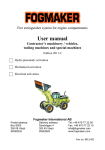
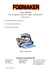
Fogmaker Universal User Manual Fogmaker Universal User Manual Fogmaker is a registered trade mark for fire extinguishers used to protect engine compartments of fork lifts, front loaders, forestry and construction machines, buses or other heavy vehicles, engine compartments and cockpits of racing and rally cars, engine compartments of veteran cars, engine and fuel tank compartments of leisure boats and other small boats. Fogmaker Universal will work and discharge the extinguishant regardless of the position or angle in which it is installed or hangs when it is activated. It uses a patented solution to offer a safer function than traditional, bottle-type fire extinguishers. The difference is that traditional extinguishers use a vertical evacuation pipe, which could reduce or completely take out the effect if the extinguisher is activated when it is held or hangs in an upside down or close to horizontal position. Fogmaker Universal is designed for do-it-yourself installation. It is easy to install and dismantle for servicing or refilling. The extinguishant consists of water, an anti-freeze saline solution and a film-forming chemical, which prevents reignition of any leaking fuel. PRODUCT DATA Type ID .............................................................. Serial number .............................................................. Date of delivery .............................................................. User Manual FogmakerUniversal Water-mist fire extinguisher for permanent installation. Effective against burning petrol, diesel and other liquid fuels in engine rooms and other enclosed spaces. Fogmaker Universal is manufactured and marketed by: Box 3204 Phone: +46 470 243 40 SE-352 53 VÄXJÖ Fax: +46 470 244 40 SWEDEN Fogmaker Universal, User Manual, Page 20 (20) E-mail: [email protected] Homepage: http://www.fogmaker.com Edition 2002 Fogmaker Universal, User Manual, Page 1 (20) Edition 2002 Fogmaker Universal User Manual Fogmaker Universal User Manual 12. Technical Data Type Fogmaker is a registered trade mark of the fire extinguisher described in this manual. It is designed for extinction of burning petrol, diesel, oil etc. in engine rooms or other enclosed spaces. The extinguisher uses a cold water-mist, which reduces the temperature very effectively. At the same time it drives out the air, so that the oxygen level is reduced. Full effect is obtained when the extinguishant is vaporized. Fogmaker Universal consists of the following parts: General description Installing the Cylinder Valve Hose Release Valve Manual Activation Electrical Activation Pneumatic Activation - Firetrace Pipes Couplings Firetrace Components Nozzles Double-assembled Extinguisher Cover Boxes Installations in Racing Cars Functionality Check after Installation Measures in the Event of Fire Measures after Fire Checklist Schedule Restoring the Function after a Fire Winter Storage Technical Data Section Section Section Section Section Section Section Section Section Section Section Section Section Section Section Section Section Section Section Section Section 1.1 1.5 2.2 2.1 3.1 3.2-3.3 3.4 4.1-4.2 4.3-4.3.2 4.5 4.6 5 5 5.3 6 7 8 9 10 11 12 Universal 33 Universal 40 Measures (mm) Measures (mm) Diameter excl. assembly fittings 152 152 Maximum measure from wall incl. assembly fittings 165 170 Maximum width incl. assembly fittings 152 390 Length (height) incl. valve 400 445 Hole distance on assembly fittings w 350, h 280 (M8) We i g h t Filled cylinder incl. assembly fittings (approx. kg) 11 23 Volume, pressure Volume, extinguishant (approx. litres) 3.3 4.0 Volume, driving gas (approx. litres) 66 80 Load pressure (at +20oC) 100-105 bar 100-105 bar Test pressure, cylinder (bar) 144 144 Materials Cylinder Extruded durable aluminium Assembly fittings Aluminium, stainless stell fastening clamps Valve Brass, components of stainless steel Anodizing, all aluminium parts, interior & exterior Min 20 µm Min 20 µm Discharge time (approx, seconds) 2 nozzles 4 nozzles 6 nozzles 8 nozzles The pipes are not exposed to pressure until the release valve has been activated. 10 nozzles 12 nozzles Nozzle flow at 100 bar 120 60 40 30 Fogmaker 66 48 40 Approx. 80 litres/hour per Other specifications Driving gas Extinguishant Anti-freeze temperature (standard) Nitrogen Water, antifreeze and film-forming agents -35o C 78 52 39 Fogmaker 80 62 52 nozzle Functionality tests and technical approvals: Institute SAQ Kontroll AB Pressure vessel approval Standard AFS 1994:39 (-40/+65 oC) Date 97-02-12 Swedish National Testing and Research Institute (SP) Swedish Administration of Extinguishing test 96-06-18 Shipping and Navigation Regulations 1996-01-11 in 5 m3 space International Car Sport Federation (FIA) Art. 253 Safety Equipment 96-12-02 Homologation No. Ex.001.97, Techn. List No. 16 (Groups N, A, B, ST) Swedish Administration of Shipping and Navigation Type approval 97-02-04 Leisure boats, engine compartment < 5 m3 Swedish Fire Safety Association (SBF) Approval of extinguishing capacity in peat loader Fullscale test (SBF) for homologation with regard to water quantity. Approval extinguishing capacity 1.2 litres/m3 Fogmaker Universal, User Manual, Page 2 (20) Edition 2002 Fogmaker Universal, User Manual, Page 19 (20) RUS 127 98-05-18 SBF 127 SBF 127 01-09-15 01-09-15 Edition 2002 Fogmaker Universal User Manual In normal circumstances, Fogmaker Universal does not affect the function of engines. If extinguishant should be sucked into the air intake of the engine, this normally does not affect the performance. You may, however, experience difficulties starting diesel engines since the incoming extinguishant contains water. Please note that the extinguishant can cause corrosion damage if the engine is not restarted shortly after a fire. As a precaution, pour a little oil into the cylinders and run the starter engine for a few seconds. The function of the electrical system can be affected by the saline solution of the extinguishant, resulting in unwanted flashovers if the system is not cleaned as soon as possible. After removing the cause of fire and cleaning the protected equipment you can begin using it again, provided the fire itself has not caused any damage which must be repaired first. 10.1 Restoring the Function of FogmakerUniversal after Extinction When Fogmaker Universal has been used, the cylinder must be refilled with extinguishant. This should be done at an authorized service station. Take the following steps when Fogmaker is dismantled for maintenance and service: 2. 3. 4. 5. 6. 7. 8. User Manual 1. Extinguishant Cylinder 10 Effects of Activation 1. Fogmaker Universal Unfasten the coupling between the release valve and the hose that connects the cylinder to the piping. Disconnect the pull-cable(s) from the release valve. Remove the cylinder from its assembly fitting and bring it to an authorized service station for checking and refilling. Remove the nozzles and flush the system using a mixture of water and rinsing fluid (rinsing fluid and tools for this purpose can be ordered from Fogmaker). When this has been done you should blow the pipes clean with compressed air Rinse the nozzles under running water and blow them clean using compressed air. Check the O-ring packing on the nozzle. Replace if required. Reinstall the nozzles. Clean and reinstall the protective hoods on the nozzles, or fit new hoods. 1.1 General Description (Fig. 1) The cylinder (1) of Fogmaker 33 is made from extruded aluminum alloy. It has been anodised to about 20 my, which makes it extremely resistant to corrosion even in very demanding environments, for example exposure to saline sea air. The bottom of the cylinder is equipped with a refilling valve (2) for driving gas. The lid is equipped with a refilling valve (3) for extinguishant, release valve (4), valve outlet with safety plug (5), pressure gauge (6), transport safety screw (7), detector gas connector (8) and power inlet for an electrical extinguisher (9). The installation kit includes an assembly fitting (10) and fastening clamps (11). Fogmaker Universal is also available in a double-assembled model. Fogmaker Universal 66, 80 (Fig. 1D). WARNING It is strictly forbidden for unauthorized personnel to tamper with the valve or lid of a pressurised cylinder. This may release the pressure of the cylinder and cause serious injury to a person. You must not remove the safety screw (7) until the installation has been completed! 3 5 6 Fig. 1 Fogmaker Universal 22, 33 and 40 11 7 1 When the cylinder has been refilled, reinstall it using the same procedure as when you first installated it. 10 11 Winter Storage Since the extinguishant of Fogmaker Universal contains water, it normally includes an anti-freeze agent for temperatures down to about -35°C, if nothing else has been agreed. 4 Fig. 1 B 8 If Fogmaker Universal is installed in an unheated space under winter conditions where the temperature might fall below the freeze protection limit, the extinguisher must be removed for the winter. Fig. 1 D Fig. 1 C Dismantling is done in the same way as after a fire (section 10.1). If the cylinder has not been activated, you must first secure it with the safety screw. 2 WARNING 12 When dismantling a cylinder that has not been discharged, you must fasten the safety screw (7) before disconnecting the piping and activation device. Insert the safety plug into the valve outlet before the fire extinguisher is removed from the vehicle or filled/serviced on location. Fogmaker Universal 66 and 80 9 Fogmaker Universal, User Manual, Page 18 (20) Fogmaker Universal, User Manual, Page 3 (20) Edition 2002 Fogmaker Universal User Manual Fogmaker Universal User Manual 1.2 Extinguishant 9. Checklist Schedule - Fogmaker Fire Extinguisher and Sprinkler System 1.3 Continuous Check-ups The extinguisher system should be checked once a year using the checklist below. Every four years, an extended check-up of the cylinder should be carried out and the extinguishant replaced. Extended check-ups can only be done at an authorized service station. The extinguishant consists of water, an anti-freeze agent (-35 oC) and other additives, the purpose of which is to facilitate extinction and prevent reignition. The extinguisher should be checked regularly (see Section 9). Functionality tests and refilling should be carried out by authorized personnel in accordance with the specifications on the cylinder service label. The cylinder (Fig 1) should be checked regularly for any visible damage or defects. The pressure is checked by reading the pressure gauge (6), which should indicate about 100 bar. If the pressure is below 90 bar at +20oC the extinguisher should be refilled, in order to ensure full functionality. Fogmaker Universal also works at lower pressure, but the size of the water drops will increase, resulting in less effective formation of water-mist. The extinguishing effect is optimized at a pressure of approximately 70-100 bar. 1.4 Refilling On delivery, the fire extinguisher is pressurized and filled with extinguishant. Refilling should be done at an authorized service station. A special tool is required to refill the cylinder. The cylinder contains driving gas (nitrogen), which is refilled from the bottom of the cylinder through a valve (2). If you refill the cylinder shortly after it has been discharged, the original driving gas can be recompressed and used again. If the cylinder has been disassembled for servicing you must, however, refill both driving gas and extinguishant. 1.5 Installing the Cylinder Install the cylinder close to the room that is to be protected, using the assembly fitting (10) and clamps (11, Fig. 3) that are included in the installation kit. Screws are not enclosed since you may need different types depending on where and how the cylinder is to be installed. The assembly fitting, or the installation profile, should be fixed in such a way that there is enough free space around the release valve to connect the pipes to the nozzles, the release pull-cable(s) and an electrical release equipment, if required. The cylinder can be set up in whichever position you want, but make sure that the pressure gauge can be checked. If it is not possible to install the cylinder with the pressure gauge fully visible, we recommend that you use an electrical pressure alarm. For instructions on how to install pipes, nozzles and activation devices, see sections 3 and 4. Fig. 2A 13 7 Fig 2B 17 15 4 9 Checklist - Daily Check-up Check that the pressure of the cylinder is not below 90 bar and the detector pressure (Firetrace) at least 15 bar. This check-up is not required if you use an electrical activation device. Checklist - Annual Check-up 9.1 Extinguisher cylinder 9.1.1 Assembly fittings, fastenings 9.1.2 Cylinder clamps, fastening 9.1.3 Check pressure gauge, min 90 bar 9.1.4 Visible leaks 9.1.5 Marking label, check-up 9.1.6 Yellow labels, check-up 9.1.7 555 or equivalent on valve mechanism 9.2 Pull-cable (one or two cables) 9.2.2 Fasten the safety screw 9.2.3 Functionality check, lubrication 9.2.4 Pull-handle and safety catch 9.2.5 Sticker ”Fire” on handle, change if required 9.2.6 Remove the safety screw 9.3 Sprinkler system 9.3.1 Pipes/hose – cracks, fractures etc. 9.3.2 Pipes/hose – clamps, sagging X Test blowing, compressed air 9.3.4 Tighten pipe/hose couplings and nozzles 9.3.7 Nozzle spray direction, check-up/adjustment, 9.4 Detection system, electrical 9.4.1 Cable circuit - crushing, cracks, fractures 9.4.2 Alarm circuit and alarm, check-up 9.5 Detection system, Firetrace 9.5.1 Visual inspection of Firetrace hose and its fastenings 9.5.2 Alarm circuit and alarm, check-up Notes X X X X X X X Serial number, next service X X X X X X X X X 9.3.3 Check free flow through all nozzles X X X With regard to wear, heat and aging defects. X Systems in accordance with SBF 127 See special checklist for each system. 16 For electrically triggered systems there are additional checks, which are described in the relevant user manual. 14 18 15 5 6 Fogmaker Universal, User Manual, Page 4 (20) 18 17 Edition 2002 Fogmaker Universal, User Manual, Page 17 (20) Edition 2002 Fogmaker Universal User Manual Fogmaker Universal User Manual 2. Release Valve 7. Measures in the Event of Fire The following measures should be taken in case there is a fire in the protected room: 1. Stop engines and ventilators 2. Turn off the electricity 3. Shut, if possible, the doors/hatches to the room 4. Activate Fogmaker Universal If the system is not fully automatic or if it is in manual mode: Use the pull-cable(s) or press the release button 5. Shut down the fuel supply to the engine 6. If possible, keep the protected room closed for five minutes after extinction. You should have a hand-held extinguisher prepared, if the fire should flare up again. WARNING When the safety screw (7) and the protective cover (17) have been removed, Fogmaker Universal can be accidentally activated by a slight pressure to the release catch which is located under the protective cover (16). The release valve must not be dismantled if the cylinder is pressurized. If the valve or any of its nipples are removed when the cylinder is under pressure a liquid jet, strong enough to injure a person seriously, will be discharged. 2.1 Release Valve (Fig. 2A, 2B) 8 Measures after Extinction Fogmaker Universal contains an anti-freeze agent, a corrosion inhibitor and a film-forming liquid (which is decomposed by nature’s own organisms). However, when the extinguishant dries up, the corrosion inhibitor loses its effect. In order to avoid corrosion, you should clean any metal parts as soon as possible after the system has been discharged. This is done by rinsing the equipment with fresh water, preferably using a high-pressure washer. We also recommend that you use an alkaline detergent, to facilitate the removal of the film-forming chemical. If this is not done properly, any remaining film may gather dust and dirt. Fogmaker Universal can be activated manually, electrically from a control panel, or automatically through a detector circuit, see Fig 2A. The valve could also be automatically activated using a pneumatic device (Firetrace), see Fig. 2B. Fogmaker International AB provide a range of central units – manual, semi-automatic or fully automatic - which can be used to control the electrical release device. Contact your retailer for further information. The release valve (4) is attached to the lid of the cylinder (15). The valve has an outlet opening (5) for the extinguishant. For security reasons the outlet is equipped with a safety plug, which should always be inserted before you service or transport a pressurized cylinder. There are two sockets for pull-cables (13). The valve is secured from accidental activation by a safety screw (7), which should always be in place when servicing or installing/dismantling the extinguisher and when transporting a pressurized cylinder. Electrical activation connector cables (9). Two protective covers (16 and 17) will prevent dirt from affecting the function of the release mechanism. The safety screw should be removed when the cylinder has been installed and you want to take the extinguishing system into operation. At all other times the safety screw should be mounted, in order to prevent unintentional activation. Keep the safety screw hanging by the wire (18) when you have unfastened it. Fig 2B displays the fully automatic pneumatic valve and the connector for the pneumatic hose (18). Pneumatic detection can not be combined with pull-cables. For mechanical activation of Firetrace, see section 3. Fig. 3 2.2 Valve Hose NOTE In order to protect the engine, electrical fittings and other metal parts from corrosion, you should wash away any remains of dried or damp extinguishant as soon as possible after the extinguisher has been discharged (preferably using a high-pressure washer). This should always be done, whether the extinguisher has been activated in connection with a fire or for any other reason. The valve outlet and the sprinkler system are connected through a valve hose. This hose is designed to absorb vibrations and thereby prevent vibration damage to the pipes. 10 11 11 Fogmaker Universal, User Manual, Page 16 (20) Edition 2002 Fogmaker Universal, User Manual, Page 5 (20) Edition 2002 Fogmaker Universal User Manual Fogmaker Universal 3. Activation Devices (Fig. 4A, 4B, 4C) Installation Fogmaker International supply devices for manual activation with pull-cables, for electrical or pneumatic activation, see sections 3.2 - 3.3. User Manual Fig. 15A Example of pipe and nozzle installation 3.1 Activation Pull-cables Two activation pull-cables can be connected to the electrical/mechanical valve, see Fig. 4B and 4C. The cables are fixed to a wall etc. with steel rubber clamps and sheet-steel screws. Clamps should be used approximately every 30 cm along the wire casing. It is important that you install the cable in such a way that there is no risk of fractures. You should also make sure that any curves on the cable are not so sharp that activation is made difficult or obstructed. The pull-handle should be installed in an easily accessible place outside the area Fogmaker Universal will protect in case of fire. When the extinguisher is installed in a vehicle, one handle should be placed next to the operator’s/driver’s seat and the other on the outside of the vehicle. The handles are equipped with a catch (see Fig. 4D). The outside handle should be placed so that it can not be affected by, for example, a branch or any other outer obstacle. If used in a competition car (racing/rally), the handles should be labelled with an (E) sticker. In order to ensure adequate function of the pull-cables, please follow these instructions: 1 Drill an 8 mm hole where the handle is to be placed. Unscrew the outer of the two M8 nuts and insert the cable holder ”from the back”. Attach the safety catch, if this is to be used, and fasten the outer M8 nut again and pull it tight. Then, pull the M8 nut ”on the back” tight. 2 Attach the enclosed M5 nut and the T-handle to the cable. Lock the T-handle in a suitable position with the M5 nut. It is particularly important, if the safety catch is used, to make sure that it can be opened/closed with an adequate inertia. 3 Use clamps to secure the cable casing except for the last 50 cm closest to the valve. WARNING Make sure that the valve safety screw (7) is mounted, before you start installing the pull-cables, so that Fogmaker Universal is not accidentally activated during the installation. 4 5 Remove the valve protective cover by unscrewing the socket screw 19 Use the T-handle to pull the cable about 12-15 cm out of the casing. Cut the casing to a suitable length. Fig. 4C Fig. 4B 6. Functionality Check after Installation 6.1 Fogmaker Universal has been subjected to functionality and leakage tests for at least two weeks as part of the production process and it will work when activated, provided that activation devices and the piping have been correctly installed and that the safety screw has been removed. It is therefore not necessary to test the extinguisher itself. If you are in any doubt about the functionality of the system, you should contact an authorized service station for a check-up. 6.2 Check the piping for leaks using compressed air, which you connect to the pipe end where the extinguisher will be connected. Then, apply leak spray to all couplings and joints and observe them. 6.3 Firetrace is checked after the valve has been pressurized with detector gas, after which all joints and couplings should be tested with leak spray. Repair any leaks. The pressure gauge of the Firetrace system should then be observed daily for at least a week. After this you make a new test using leak spray. Check that the resistance of the alarm cable is correct, 0 ohm. Fig. 4A 16 19 Fogmaker Universal, User Manual, Page 6 (20) Edition 2002 6.4 For electrical systems you should check that the wiring is OK and that there are no defective connections. Check the detector circuit and the power supply inlet on the valve using a measuring instrument. The resistance of the detector circuit should be 1 kohm. The power inlet should be between 1.5 and 2 ohm. Make a system test by pushing the test button of the central unit or control panel, (only rus and 1717) Fogmaker Universal, User Manual, Page 15 (20) Edition 2002 Fogmaker Universal User Manual Fogmaker Universal User Manual 6 7 Push the cable out of its casing again and attach the end socket/tensioners on the casing. Cut the cables to 26 and 31 mm, respectively (Fig.4A). Slip the cable through the M6 hole of the valve housing and screw on the cable tensioners. 8 Attach the cable screw-nipples (see Fig. 4B) 9 Insert the cable nipples into the milled-out grooves of the release catch, (Fig. 4C). Fasten the cover (16). The cover will hold the cable nipples in place. 1 0 Fasten the last clamp as close to the valve as possible, in order to ensure that the cable casing is properly fixed so that it can not move. Fig.15B WARNING When checking that the cable runs smoothly, the safety screw (7) of the release valve must be mounted. This way the extinguisher will not be activated when you pull the handle, but you will be able to establish that the cable runs smoothly and that the gap is sufficient (1-5 mm). You should test the cable before it is attached to the valve. 3.2 Electrical Activation As an alternative to manual activation, the valve can be activated electrically. The operator activates the unit manually by pushing a button which activates and discharges the extinguishing system electrically. Activation pull-cables can be combined with electrical activation. 3.3 Detector Activation If Fogmaker Universal is installed to protect an unattended space, you need a fully or semi-automatic system which triggers extinction through detectors and a central unit in case of fire. Detectors, which react to, for example, increasing temperature, smoke or visible flames, can be used. Fogmaker International AB has developed several types of central units and alarm panels for different applications. We offer optional accessories such as visual and acoustic alarms as well as automatic engine, fuel and electricity shutdown mechanisms. Contact Fogmaker or your retailer for further information. For installation instructions, see the user manual concerned. Fig. 5 5.3 Installation in Racing Cars Singel-seaters should be equipped with four spray nozzles in the engine compartment, one of which should be directed down towards the bottom plate of the engine compartment. One nozzle should be placed either to the left or the right of the driver’s helmet, pointing towards his/her knees. The same principles apply when installling Fogmaker in the engine compartment of a standard car. Inside the cockpit, you should place one nozzle on each B post, as high up as possible. Install the nozzles pointing crosswise down towards the driver’s/passenger’s feet. This means that the nozzle on the right-hand B post should be directed towards the passenger’s feet. Make sure that the water-mist is not obstructed by the driver or passenger. These systems should be equipped with double activation devices. The first should be easy to reach for the driver, while the other should be placed on the outside of the car, clearly visible. Both activation devices should be labelled with an (E) sticker. Fogmaker Universal, User Manual, Page 14 (20) Edition 2002 Fogmaker Universal, User Manual, Page 7 (20) Edition 2002 Fogmaker Universal User Manual Fogmaker Universal User Manual 5. Double-assembled Extinguisher, Cover Boxes 3.4 Pneumatic Activation - Firetrace Firetrace is a fully automatic, pneumatic system. The system consists of a detector gas cylinder and a polymer hose, which is installed in the engine room at ceiling level round the engine. In the event of a fire the hose is burnt off, the pressure drops and the valve of the Fogmaker cylinder is automatically opened to discharge the extinguishant into the nozzle system. The detector gas cylinder is equipped with a connector for a pressure guard. The hose can be punctured by hand using a manual activation device (not standard equipment). Optional accessories are alarm panels, visual and acoustic alarms, as well as automatic engine, fuel and electricity shutdown mechanisms. Fig. 6 5.1 Double-assembled Extinguisher (Fig. 14) FOGMAKER ® Universal is also available in a double-assembled version suitable for large machines and vehicles. The volume of extinguishant is doubled to 6.6 litres, providing enough capacity for a sprinkler system with 11 to 15 nozzles. The maximum capacity of a FOGMAKER ® Universal with 3.3 litres of extinguishant, is 6 to 8 nozzles. The double-assembled extinguisher is fixed to its assembly fittings when delivered, and the cylinders are connected with a hose (se Fig. 14). When installing the cylinders you must not disconnect them from the assembly fittings, since this might affect the connector coupling between the hose and the lid of the cylinder and cause leakage. 5.2. Cover Boxes (Fig. 13) Fogmaker International AB market a cover box of powder coated sheet-steel for single as well as doubleassembled cylinders. These boxes are primarily used for outside assembly on vehicles and machines that are used in difficult conditions. 4. Pipes, Couplings and Nozzles (Fig. 11-11A) 4.1 Pipes Double-assembled extinguisher 6,6 and 8 litres The standard kit includes 6 x 0.8 mm soft, treated copper pipe (1) of the required length in accordance with your order. As an alternative you can use pipes of steel (stainless or not) or steel-reinforced rubber hose, as well as combinations of these. Copper pipes are, however, easier to handle if you are doing the installation yourself. They can be bent into flexible curves, which can be adapted to the layout of the protected room. The pipes can not, however, be bent too many times, as the material hardens. If the pipe has to be rebent it must first be annealed. Pipes of plastic or other materials can not be used, since they may burst because of the high pressure. According to the motor sport regulations of FIA valid from 1 January 1998, the piping must consist of a fire resistant material. 4.2 Pressure Drop Pressure drop per metre pipe The Fogmaker system uses high pressure. Therefore it is important to use the appropriate dimensions for the pipes so that unneccessary drops in the pressure are avoided. If the pressure should drop, the efficiency of the system is reduced. The chart displays the pressure drop per metre pipe when using 6x1 mm copper pipe and 8x1 steel pipe, respectively. The drop should not exceed 1 bar per metre. For information on the flows which should be calculated, see section 12 Technical Data. For long distances we recommend that you use 8 mm pipes for the feeder line and 6 mm pipes for the nozzle branches. When cutting the pipes into suitable lengths a special pipe cutting tool should be used, to avoid leaving burrs in the cut-off pipe ends. Fogmaker Universal, User Manual, Page 8 (20) Edition 2002 Cover box Fig. 13 Fig.14 Fogmaker Universal, User Manual, Page 13 (20) Edition 2002 Fogmaker Universal User Manual Fig. 10 4.5 Firetrace 2 Firetrace Installation Kit 5 6 IMPORTANT 7 4 8 11 10 The nozzle consists of a body (1) with a built-in turbulence former and a fixed, sintered filter (2). Around the body an O-ring (3) is placed. The end of the nozzle has a hole from which the watermist is discharged. To prevent the hole from getting clogged up by dirt, dust etc. a protective hood (4) is included in the delivery. This hood should remain on the nozzle after installation. It will be forced off by the released pressure when water-mist is created. When assembling the nozzles you should use a thread-locking liquid or thread-tape. Please note, that it is very important to make sure that the thread-tape does not come loose and enter into the piping, since this could obstruct the nozzle filters. 1 Fig. 11 3 Blow the pipes clean before installing the nozzles. Any filings and burrs may reduce the diameter of the pipes and nozzles, resulting in restricted throughflow of extinguishant when Fogmaker Universal is activated. 9 4.6 Nozzles 2 User Manual The pipes are installed with clamps (Fig. 9 A och B) and screws. Use one clamp per 30 cm of pipe. We recommend that you use clamps on both sides of couplings. Use a sufficient number of clamps, so that the pipes do not vibrate or sag. 1 1. Detection hose 2. Detector gas cylinder with pressure gauge, valve and pressure guard, filled on delivery, 18 bar. 3. 2 cylinder assembly fittings (not in picture) 4. T coupling. You can order the articles below: 5. Angle 1/8”-6 6. Bulkhead fitting 6-6. 7. End coupling 1/8”-6 8. Joint 6-6 9. End coupling with protective spring 6 10. Pressure guard for alarm 11. Rubber clamp 6 mm with screws Manual activator (cuts hose) (not in picture). Fogmaker Universal 4 Fig. 12 Install the nozzles in “the ceiling” of the protected room. They should be 70-90 cm apart and 30-45 cm from a wall in order to obtain the most effective distribution of the flow. The nozzle will spray the water-mist in a cloud, at an initial spreading angle of approx. 110°. The spray will bend off at a point about 20-25 cm from the centre of the discharge. It will then spread with full force in the form of a pillar with a diameter of 50-60 cm at a distance of about 100 cm from the nozzle. The flow from separate nozzles should be directed so that the mist-clouds do not neutralize each other (“collide”). There should be as few objects as possible in the way, so that the formation of mist is not affected. Fire extinction will become more effective if the nozzles are directed towards spots where a fire might start, for example the atomiser pipes of a diesel engine or the carburettor of a petrol engine. Preferably, the mist should hit some hot components, for example the turbo, since this will speed up the vaporization and thereby the extinction. Fogmaker Universal, User Manual, Page 12 (20) 4.3 Installing Pipes When the pipes have been cut to a suitable length and the ends have been cleared as described in section 4.1 you proceed by installing the couplings. The pipe you are going to connect to the release valve must first be drawn through the wall separating the protected room and the area where the extinguisher will be installed. To do this you need a bulkhead fitting of nickel-plated brass (Fig. 9 A and B), which is a standard item in the installation kit. Connect the pipe to the bulkhead fitting. On the outside of the wall you should now install the valve hose which connects the extinguisher valve to the sprinkler system. How to connect pipes and couplings: slip the nut onto the pipe end slip the inner clamp ring on the pipe end. NOTE: make sure it is in the right direction! insert the pipe end into the coupling, lubricate the thread and sleeve using copper grease and pull the nut tight, thereby locking the clamp ring check that the pipe is properly locked in the coupling Fig. 8 Tighten the nuts, first by hand and then another 3/4 of a turn using a tool. Install the nozzles using angle couplings (type 2 Fig 9 A) or T-couplings (type 6 Fig 9 B) in combination with sleeve couplings (type 13 Fig. 9 B). You can also use pipe ends in combination with end couplings (type 4) where the nozzles can be installed. Bend the pipe to the smallest possible radius, without deforming the pipe, so that the nozzle, when it has been installed, points inwards and downwards towards the specific area you want to protect. These couplings are not included in the standard installation kit, but they can be supplied if you place a special order for the required quantity. Fix the nozzle using a suitable mounting or a clamp so that the nozzle is not dislodge out of position. 4.4 Couplings The standard kit includes the following brass clamp ring couplings. (NOTE: If steel pipes are installed, you must use steel couplings.) • Valve hose with nipples (9, 11 och 12 Fig. 9 A and B) used to connect the valve to the piping (see separate installation instructions enclosed with the hose kit) • Straight nozzle coupling (type 4 Fig 9 A) for nozzles (quantity = number of nozzles). • T-coupling (type 6, Fig 9 A) for joining pipes or for direct mounting of nozzles using doublesleeve couplings (type 13, Fig. 9 B). • You can also order the required number of angle couplings (2) for direct connection of nozzles. 4.4.1 Coupling Kits Examples of kits The standard installation kit includes clamp ring couplings of brass as illustrated on page 10. (NOTE: If steel pipes are installed, you must use steel couplings.) Edition 2002 Fogmaker Universal, User Manual, Page 9 (20) Edition 2002 Fogmaker Universal User Manual Fogmaker Universal The following items are included in the kits. Kits can be ordered for 2-6 nozzles. o Installation kit 1504: (1) 6 mm steel rubber clamp with screw. (2) 90 angle coupling 6x1/4” male (not standard). (3) Nozzle with filter and protective cover. (4) End coupling 1/4”-6 male. (5) Bulkhead fitting 6-6. (6) T-coupling 6-6-1/4”. (7) End coupling 1/4”-6 male. (8) Copper pipe 6x1 6,2 metres. (9) Valve hose. (10) Valve hose clamp with screw. (11) Sleeve coupling 1/4”-1/4” female. (12) Adapter 1/4” male-1/4” female. User Manual o Installation kit 1514: (1) 6 mm steel rubber clamp with screw. (2) 90 angle coupling 6x1/4” male (not standard). (3) Nozzle with filter and protective cover. (4) End coupling 1/4”-6 male. (5) Bulkhead fitting 6-6. (6) T-coupling 6-6-1/4”. (7) End coupling 1/4”-6 male. (8) Copper pipe 6x1 6,2 metres. (9) Valve hose. (10) Valve hose clamp with screw. (11) Sleeve coupling 1/4”-1/4” female. (12) Adapter 1/4” male-1/4” female. (13) Sleeve coupling 1/4” male-1/4” female. Fig. 9B Fig. 9A 1 2 3 5 6 7 1 2 4 3 13 6 7 5 4 8 10 8 10 9 11 9 12 11 Fogmaker Universal, User Manual, Page 10 (20) Edition 2002 12 Fogmaker Universal, User Manual, Page 11 (20) Edition 2002