1
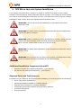
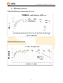
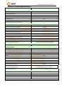
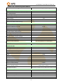
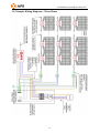
ALTENERGY POWER SYSTEM, INC.
APS M1P-EU
Grid-connected Micro-inverter
Installation and User Manual
Version: 1.2
ALTENERGY POWER SYSTEM, INC.
All rights reserved
1
ALTENERGY POWER SYSTEM, INC.
Contact Information
ALTENERGY POWER SYSTEM Inc.
1 Yatai Road, Jiaxing, PR China 314050
Phone: +86-21-68889199
Fax: +86-21-33928752
www.altenergy-power.com
[email protected]
2
ALTENERGY POWER SYSTEM, INC.
Table of Contents
1.
Important safety information .......................................................................................................................... 4
Symbols replace words on the equipment, on a display, or in manuals. ............................................................. 4
Safety Instructions .............................................................................................................................................. 5
2.
APS Micro-inverter System Introduction ....................................................................................................... 5
3.
APS Micro-inverter M1P series Introduction ................................................................................................. 8
4.
APS Micro-inverter System Installation ........................................................................................................10
Additional Installation Components from APS .................................................................................................10
Required Parts and Tools from you ...................................................................................................................10
Installation Procedures ....................................................................................................................................... 11
Step 1 - Installing the AC Branch Circuit Junction Box ................................................................................ 11
Step 2 - Attaching the APS Micro-inverters to the Racking or the PV Module Frame ..................................12
Step 3 - Connecting the APS Micro-inverter AC Cables ...............................................................................13
Step 4 - Ground the System ...........................................................................................................................13
Step 5 - Connecting APS Micro-inverters to the PV Module ........................................................................14
Step 6 - Completing the APS Installation Map ..............................................................................................14
Step 7 – Placing a Warning Notice ................................................................................................................14
5.
APS micro-inverter system operating instructions ........................................................................................16
6.
Troubleshooting .............................................................................................................................................16
Status Indications and Error Reporting ..............................................................................................................16
Operation LED ..............................................................................................................................................16
GFDI Error ....................................................................................................................................................16
Other Faults ...................................................................................................................................................16
7.
Maintenance...................................................................................................................................................17
8.
Replace a micro-inverter................................................................................................................................18
9.
Efficiency Curves ..........................................................................................................................................19
10.
Technical Data ...........................................................................................................................................20
11.
Wiring Diagram ............................................................................................................................................23
11.1 Sample Wiring Diagram – Single Phase ....................................................................................................23
11.2 Sample Wiring Diagram – Three Phase .....................................................................................................24
3
ALTENERGY POWER SYSTEM, INC.
1. Important safety information
This manual contains important instructions to follow during installation and maintenance of
the APS Photovoltaic Grid-connected Micro-inverter. To reduce the risk of electrical shock
and ensure the safe installation and operation of the APS Micro-inverter, the following
symbols appear throughout this document to indicate dangerous conditions and important
safety instructions.
WARNING: This indicates a situation where failure to follow instructions
may cause a serious hardware failure or personnel danger if not applied
appropriately. Use extreme caution when performing this task.
NOTE: This indicates information that is important for optimized
Micro-inverter operation. Follow these instructions closely.
Symbols replace words on the equipment, on a display, or in manuals.
Trademark
Caution, risk of electric shock
Caution, hot surface
Symbol for the marking of electrical and electronics
devices according
to Directive 2002/96/EC. Indicates that the device, accessories and the
packaging must not be disposed as unsorted municipal waste and must
be collected separately at the end of the usage. Please
follow Local
Ordinances or Regulations for disposal or contact an authorized
representative of the manufacturer for information concerning the
decommissioning of equipment.
CE mark is attached to the solar inverter to verify that the unit follows
the provisions of the European Low Voltage and EMC Directives
Refer to the operating instructions
4
ALTENERGY POWER SYSTEM, INC.
Person adequately advised or supervised by an electrically skilled person
to enable him or her to perceive risks and to avoid hazards which
electricity can create. For the purpose of the safety information of this
Qualified
manual, a "qualified person" is someone who is familiar with
personnel
requirements for safety, refrigeration system and EMC and is authorized
to energize, ground, and tag equipment, systems, and circuits in
accordance with established safety procedures. The inverter and endues
system may only be commissioned and operated by qualified personnel.
Safety Instructions
•
Only qualified professionals should install and/or replace APS Micro-inverters.
•
Perform all electrical installations in accordance with local electrical codes.
•
Before installing or using the APS Micro-inverter, please read all instructions and
cautionary markings in the technical documents and on the APS Micro-inverter
system and the PV-array.
•
Be aware that the body of the APS Micro-inverter is the heat sink and can reach a
temperature of 80°C. To reduce risk of burns, do not touch the body of the
Micro-inverter.
•
Do NOT disconnect the PV module from the APS Micro-inverter without first
disconnecting the AC power.
•
Do NOT attempt to repair the APS Micro-inverter. If it fails, contact APS Customer
Support to obtain an RMA number and start the replacement process. Damaging or
•
opening the APS Micro-inverter will void the warranty.
Caution!
The external protective earthing conductor is connected to the inverter protective
earthing terminal through AC connector.
When connecting, connect the AC connector first to ensure the inverter earthing
then do the DC connections.
When disconnecting, disconnect the AC by opening the branch circuit breaker first
but maintain the protective earthing conductor in the branch circuit breaker connect
to the inverter ,then disconnect the DC inputs.
In any circumstance, do not connect DC input when AC connector is unplugged.
2.
APS Micro-inverter System Introduction
The APS Micro-inverter is an inverter system for use in utility-interactive applications,
comprised of three key elements:
5
ALTENERGY POWER SYSTEM, INC.
•
Altenergy Power Systems Micro-inverter
•
Altenergy Power Systems Energy Communication Unit (ECU)
•
Altenergy Power Systems Energy Monitor and Analysis (EMA) web-based monitoring
and analysis system
This integrated system improves safety; maximizes solar energy harvest; increases system
reliability; simplifies photovoltaic (PV) system design, installation, maintenance, and
management.
The APS Micro-inverters maximize energy production from photovoltaic (PV)
arrays. Each PV module has individual Maximum Peak Power Tracking (MPPT) controls,
which ensures that the maximum power is exported to the utility grid regardless of the
performance of the other PV modules in the array. When PV modules in the array are
affected by shading, soiling, orientation, or mismatch, the APS Micro-inverter ensures top
performance from the array by maximizing the performance of each module within the
array.
The APS Micro-inverter system is more reliable than centralized or string
inverters. The distributed Micro-inverter system ensures that no single point of system
failure exists across the PV system. APS Micro-inverters are designed to operate at full
power at ambient temperatures of up to 65°C. The inverter housing is designed for outdoor
installation and complies with the IP65 environmental enclosure rating.
6
ALTENERGY POWER SYSTEM, INC.
PV systems using APS Micro-inverters are very simple to install. You can install
individual PV modules in any combination of module quantity, orientation, type, and power
rate.
The APS Micro-inverter system provides smart system performance monitoring
and analysis.
The APS Energy Communication Unit (ECU) is installed by simply plugging it into any wall
outlet and providing an Ethernet or Wi-Fi connection to a broadband router or modem. After
installing the ECU, the full network of APS Micro-inverters automatically reports to the APS
Energy Monitor and Analysis (EMA) web server. The EMA software displays performance
trends, informs you of abnormal events, and controls system shutdown when it is needed.
7
ALTENERGY POWER SYSTEM, INC.
3. APS Micro-inverter M1P series Introduction
The APS M1P series Micro-inverters connect with the single-phase grid, and operate with
most 60 , 72 cell PV modules. For more information, please see the section 8 Technical Date
of this manual.
Model
AC grid
PV Module
YC250A
50Hz/230V
60,72 Cell
YC250I
50Hz/230V
60,72 Cell
YC500A
50Hz/230V
60,72 Cell
YC500I
50Hz/230V
60,72 Cell
YC250A
50Hz/230V
60,72 Cell
YC250I
50Hz/230V
60,72 Cell
YC500A
50Hz/230V
60,72 Cell
YC500I
50Hz/230V
60,72 Cell
Number
8
Max. #
Per branch
14 for 20A
Module Connector
MC-4 Type or Customize
breaker
14 for 20A
MC-4 Type or Customize
breaker
7 for 20A
MC-4 Type or Customize
breaker
7 for 20A
MC-4 Type or Customize
breaker
18 for 25A
MC-4 Type or Customize
breaker
18 for 25A
MC-4 Type or Customize
breaker
9 for 25A
MC-4 Type or Customize
breaker
9 for 25A
breaker
MC-4 Type or Customize
ALTENERGY POWER SYSTEM, INC.
The following figure shows the APS YC250 micro-inverter schematic:
APS YC500 has two independent DC inputs, with independent MPPT control and
data monitoring.
The following figure shows the APS YC500 micro-inverter schematic:
9
ALTENERGY POWER SYSTEM, INC.
4. APS Micro-inverter System Installation
A PV system using APS Micro-inverters is simple to install. Each Micro-inverter easily
mounts on the PV racking, directly beneath each PV module. Low voltage DC wires connect
from the PV module directly to the Micro-inverter, eliminating the risk of high DC voltage.
Installation shall comply with local regulations and technical rules.
WARNING: Perform all electrical installations in accordance with local
electrical codes.
WARNING: Be aware that only qualified professionals should install and/or
replace APS Micro-inverters.
WARNING: Before installing or using an APS Micro-inverter, please read all
instructions and warnings in the technical documents and on the APS
Micro-inverter system itself as well as on the PV array.
WARNING: Be aware that installation of this equipment includes the risk of
electric shock.
WARNING: Do not touch any live parts in the system, including the PV array,
when the system has been connected to the electrical grid.
Additional Installation Components from APS
•
Protective branch end cap(sold separately, 1 per branch)
•
AC branch end cable(sold separately, 1 per branch)
Required Parts and Tools from you
In addition to your PV array and its associated hardware, you need to provide the following:
•
An AC connection junction box
•
Mounting hardware suitable for module racking
•
Sockets and wrenches for mounting hardware
•
Continuous grounding conductor and grounding washers
•
A Phillips screwdriver
•
A torque wrench
10
ALTENERGY POWER SYSTEM, INC.
Installation Procedures
WARNING: Do NOT connect APS Micro-inverters to the utility grid or energize
the AC circuit until you have completed all of the installation procedures as
described in the following sections.
For bracket installation, after the completion of system installation rendering as follows:
Go to distribution box
Step 1 - Installing the AC Branch Circuit Junction Box
a. Install an appropriate junction box at a suitable location on the PV racking system
(typically at the end of a branch of modules).
b. Connect the open wire end of the AC branch end cable into the junction box using an
appropriate gland or strain relief fitting.
c. Wire the conductors: L- BROWN; N – LIGHT BLUE; PE –YELLOW/GREEN.
d. Connect the AC branch circuit junction box to the point of utility interconnection.
NOTE: Be sure to size the AC wire to account for voltage drop between the
AC branch circuit junction box and the point of utility interconnection. Refer
to the tables below.
11
ALTENERGY POWER SYSTEM, INC.
Step 2 - Attaching the APS Micro-inverters to the Racking or the PV Module
Frame
a. Mark the location of the Micro-inverter on the rack, with respect to the PV module
junction box or any other obstructions.
b. Mount one Micro-inverter at each of these locations using hardware recommended
by your module racking vendor.
WARNING: Prior to installing any of the micro-inverters, verify that the utility
voltage at the point of common connection matches the voltage rating on
micro-inverter label.
WARNING: Do not mount the Micro-inverter in a location that allows
exposure to direct sunlight. Allow a minimum of 1.5 centimeters between the
top of the roof and the bottom of the Micro-inverter.
12
ALTENERGY POWER SYSTEM, INC.
Step 3 - Connecting the APS Micro-inverter AC Cables
a. Check the Micro-inverter rating label for the maximum allowable number of
Micro-inverters on one AC branch circuit.
b. Plug the AC female connector of the first Micro-inverter into the male connector of
the next Micro-inverter, and so on, to form a continuous AC branch circuit.
c. Install a protective end cap on the open AC connector of the last Micro-inverter in
the AC branch circuit.
WARNING: Do NOT exceed the maximum number of Micro-inverters in an AC
branch circuit, as displayed on the unit label.
Step 4 - Ground the System
NOTE: If you already use grounding washers to ground the micro-inverter chassis to the
PV module racking as described in step 4, skip this step.
13
ALTENERGY POWER SYSTEM, INC.
Step 5 - Connecting APS Micro-inverters to the PV Module
Photovoltaic panels and micro-inverter DC input cable connection according to demand.
The inverter YC250’s DC input positive pole connect to earthed enclosure inside the
enclosure.
The inverter YC500’s DC input negative pole connect to earthed enclosure inside the
enclosure.
WARNING: Ensure that all AC and DC wiring is correct. Ensure that none of
the AC and DC wires are pinched or damaged. Ensure that all junction boxes
are properly closed.
NOTE: Step 1~5 can change sequence for convenience of installation.
Step 6 - Completing the APS Installation Map
You need to fill-in APS Warranty Cards, which provide system information and installation
map. Feel free to provide your own layout if a larger or more intricate installation map is
required.
a. Each APS Micro-inverter has removable serial number labels. Peel a label off, and affix it
to the respective location on the APS installation map.
b. Fill the warranty cards and email to APS at [email protected]
c. APS will setup the EMA account and email you information, and then you can use the EMA
website to view detailed performance of your PV system.
Step 7 – Placing a Warning Notice
A warning notice shall be placed in such a position that any person gaining access to live
parts will be warned in advance of the need to isolate those live parts from all points of
14
ALTENERGY POWER SYSTEM, INC.
supply. Special attention should be paid that the power supply, measuring circuits (sense
lines) and other parts may not be isolated from the network when the switch of the interface
protection is open.
As a minimum, warning labels shall be placed:
• On the switchboard (DNO panel and consumer unit) that has the micro-generator
connected to it;
• On all switchboards in between the consumer unit and the micro-generator itself;
• On, or in the micro-generator itself;
• At all points of isolation for the micro-generator.
15
ALTENERGY POWER SYSTEM, INC.
5. APS micro-inverter system operating instructions
To operate the APS micro-inverter PV system:
1. Turn ON the AC circuit breaker on each micro-inverter AC branch circuit.
2. Turn ON the main utility-grid AC circuit breaker. Your system will start producing power
after a two-minute waiting time.
Note: once DC power is applied, the Status LED of each micro-inverter will
blink green three times to indicate normal start-up operation.
3. The APS micro-inverters will start to send performance data over power line to the ECU.
The time required for all the micro-inverters in the system to report to the ECU will vary with
the number of micro-inverters in the system. You can verify proper operation of the APS
micro-inverters via the ECU. See the ECU Installation and Operation Manual for more
information.
6. Troubleshooting
Qualified personnel can use the following troubleshooting steps if the PV system does not
operate correctly.
Status Indications and Error Reporting
Startup LED
When DC power is first applied to the micro-inverter:
•
Three short green blinks when DC power is first applied to the micro-inverter
indicate a successful micro-inverter startup
Operation LED
Flashing Slow Green (10s gap) - Producing power and communicating with ECU
Flashing Fast Green (2s gap) – Producing power and not communicating with ECU
Flashing Red – Not producing power
GFDI Error
A solid red LED indicates the micro-inverter has detected a ground fault (GFDI) error in the
PV system. Unless the GFDI error has been cleared, the LED will remain red and the ECU will
keep reporting the fault.
After the ground fault error is fixed, follow the instructions in the ECU Installation and
Operation Manual to clear this GFDI error reporting.
Other Faults
All other faults are reported to the ECU. Refer to the ECU Installation and Operation Manual
for a list of additional faults and troubleshooting procedures.
16
ALTENERGY POWER SYSTEM, INC.
WARNING: Be aware that only qualified personnel should troubleshoot the
APS micro-inverter.
WARNING: Never disconnect the DC wire connectors under load. Ensure that
no current is flowing in the DC wires prior to disconnecting. An opaque
covering may be used to cover the module prior to disconnecting the module.
WARNING: Always disconnect AC power before disconnecting the PV module
wires from the APS micro-inverter. The AC connector of the first micro-inverter
in a branch circuit is suitable as a disconnecting means once the AC branch
circuit breaker in the load center has been opened.
WARNING: The APS micro-inverter is powered by PV module DC power.
Make sure you disconnect and reconnect the DC connections to watch for the
three short LED flashes.
Troubleshooting a non-operating APS micro-inverter
To troubleshoot a non-operating APS micro-inverter, follow the steps below in order:
1.
Verify the utility voltage and frequency are within ranges shown in the in section 8
Technical Data of this manual.
2.
Check the connection to the utility grid. Verify utility power is present at the inverter
in question by removing AC, then DC power. Never disconnect the DC wires
while the micro-inverter is producing power. Re-connect the DC module
connectors and watch for three short LED flashes.
3.
Check the AC branch circuit interconnection between all the micro-inverters. Verify
each inverter is energized by the utility grid as described in the previous step.
4.
Make sure that any AC breaker are functioning properly and are closed.
5.
Check the DC connections between the micro-inverter and the PV module.
6.
Verify the PV module DC voltage is within the allowable range shown in the Section
8 Technical Data of this manual.
7.
If the problem persists, please call APS Energy customer support.
WARNING: Do not attempt to repair the APS micro-inverter. If
troubleshooting methods fail, please return the micro-inverter to your
distributor for replacement.
7. Maintenance
No need to Maintenance.
17
ALTENERGY POWER SYSTEM, INC.
8. Replace a micro-inverter
Follow the procedure to replace a failed APS micro-inverter.
1. Disconnecting the APS micro-inverter from the PV Module, in the order shown
below:
1) Disconnect the AC by opening the branch circuit breaker. but maintain the
protective earthing conductor in the branch circuit breaker connect to the
inverter
2) Cover the module with an opaque cover.
3) Disconnect the first AC connector in the branch circuit.
4) Disconnect the PV module DC wire connectors from the micro-inverter.
5) Remove the micro-inverter from the PV array racking.
2. Install a replacement micro-inverter to the rack.
3. Connect the AC cable of the replacement micro-inverter and the neighboring
micro-inverters to complete the branch circuit connections.
4. Close the branch circuit breaker, and verify operation of the replacement
micro-inverter.
18
ALTENERGY POWER SYSTEM, INC.
9. Efficiency Curves
YC500-EU Efficiency-temperature Curves
YC500-EU Efficiency Curves
19
ALTENERGY POWER SYSTEM, INC.
10. Technical Data
WARNING: Be sure to verify the voltage and current specifications of your PV
module match with those of the micro-inverter. Refer to the APS website
http://www.altenergy-power.com for a list of approved PV modules.
WARNING: You must match the DC operating voltage range of the PV module
with the allowable input voltage range of the APS micro-inverter.
WARNING: The maximum open circuit voltage of the PV module must not
exceed the specified maximum input voltage of the APS micro-inverter.
20
ALTENERGY POWER SYSTEM, INC.
YC250-EU Technical Specifications
Type
YC250-EU
Input Data (DC)
Recommended PV Module Power (STC)Range
180-310W
MPPT Voltage Range
22-45VDC
MPPT Voltage Range @ Full Power
26-45VDC
55VDC
Maximum Input Voltage
Startup Voltage
22V
10.5A
Maximum Input Current
15A
Maximum DC Short Circuit Current
Output Data (AC)
Maximum Continuous Power
250W
Maximum Continuous Current
1.08A
230VAC
Rated Grid Voltage
1
200-270VAC (for Denmark)
Default Output Voltage Range
149-278VAC
Extended Output Voltage Range
50Hz
Rated Grid Frequency
1
47.5-50.5Hz (for Denmark)
Default Output Frequency Range
45.1-54.9Hz
Extended Output Frequency Range
Power Factor
>0.99
Total Harmonic Distortion
<3%
Maximum Units per Branch
14 for 20A Breaker/18 for 25A Breaker
Efficiency
95.5% (With HF Transformer)
Max. Inverter Efficiency
Mechanical Data
Operating Ambient Temperature
-40 °C to +65°C
Operating Internal Temperature
-40 °C to +85°C
Storage Temperature Range
-40 °C to +85°C
Dimensions (W x H x D)
160mmX 150mmX 29mm
Weight
1.5kg
Waterproof Level
IP65
Cooling
Natural Convection
Wet Locations Classification
For Wet Locations
Pollution Degree Classification
PD3
Relative Humidity Ratings
0-95%
All data at this technical Specifications
Maximum Altitude Rating
has been tested under <2000m
Overvoltage Category
OVC II for PV input circuit, OVC III for mains circuit
Features & Compliance
Communication
Power Line
Design Lifetime
25yrs
EN 50438
Grid Connection Compliance
EN 62109-1; EN 62109-2
Safety Class Compliance
1
Programmable through ECU to meet customer need.
The specifications are subject to change without notice.
21
ALTENERGY POWER SYSTEM, INC.
YC500- EU Technical Specifications
Type
YC500-EU(for 2 panels)
Input Data (DC)
Recommended PV Module Power (STC) Range
180-310W
MPPT Voltage Range
22-45VDC
MPPT Voltage Range @ Full Power
26-45VDC
55VDC
Maximum Input Voltage
Startup Voltage
22V
10.5AX2
Maximum Input Current
15A
Maximum DC Short Circuit Current
Output Data (AC)
Maximum Continuous Power
500W
Maximum Continuous Current
2.17A
230VAC
Rated Grid Voltage
1
200-270VAC (for Denmark)
Default Output Voltage Range
149-278VAC
Extended Output Voltage Range
50Hz
Rated Grid Frequency
1
47.5-50.5Hz (for Denmark)
Default Output Frequency Range
45.1-54.9Hz
Extended Output Frequency Range
Power Factor
>0.99
Total Harmonic Distortion
<3%
Maximum Units per Branch
7 for 20A Breaker/9 for 25A Breaker
Efficiency
95.5% (with HF Transformer)
Max. Inverter Efficiency
Mechanical Data
Operating Ambient Temperature
-40°C to +65°C
Operating Internal Temperature
-40ºC to +85ºC
Storage Temperature Range
-40ºC to +85ºC
Dimensions (W x H x D)
221mm X 167mm X 29mm
Weight
2.5kg
Waterproof Level
IP65
Cooling
Natural Convection
Wet Locations Classification
For wet locations
Pollution Degree Classification
PD3
Relative Humidity Ratings
0-95%
All data at this technical Specifications has been
Maximum Altitude Rating
tested under <2000m
Overvoltage Category
OVC II for PV input circuit, OVC III for mains circuit
Features & Compliance
Communication
Power Line
Design Lifetime
25yrs
Grid Connection Compliance
EN 50438
Safety Class Compliance
1
EN 62109-1; EN 62109-2
Programmable through ECU to meet customer need.
The specifications are subject to change without notice.
22
ALTENERGY POWER SYSTEM, INC.
11.
Wiring Diagram
11.1 Sample Wiring Diagram – Single Phase
23
ALTENERGY POWER SYSTEM, INC.
11.2 Sample Wiring Diagram – Three Phase
24