1
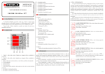
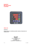
User Manual
Digital Tension Meter
Document revision: R13
Lemmen Engineering
User Manual Digital Tension Meter
February 18, 2013
Contents
1 Introduction
2
2 System specifications
3
3 Functional diagram
4
4 Panel display
5
5 DTM box
5.1 DTM box front layout . . . . . . . . . . . . . . . . . . . . . . . . . . . . . . . . . . . . . . .
5.2 DTM box dimensions . . . . . . . . . . . . . . . . . . . . . . . . . . . . . . . . . . . . . . .
7
7
8
6 Load cells
9
6.1 Load cell dimensions . . . . . . . . . . . . . . . . . . . . . . . . . . . . . . . . . . . . . . . 9
6.2 Load cell wiring . . . . . . . . . . . . . . . . . . . . . . . . . . . . . . . . . . . . . . . . . . 10
6.3 Pin assignment load cell connector . . . . . . . . . . . . . . . . . . . . . . . . . . . . . . . 10
7 DTM installation
12
7.1 Calibration . . . . . . . . . . . . . . . . . . . . . . . . . . . . . . . . . . . . . . . . . . . . 12
7.2 Normal operation . . . . . . . . . . . . . . . . . . . . . . . . . . . . . . . . . . . . . . . . . 14
8 Recommendations
15
8.1 Installation . . . . . . . . . . . . . . . . . . . . . . . . . . . . . . . . . . . . . . . . . . . . 15
8.2 Maintenance . . . . . . . . . . . . . . . . . . . . . . . . . . . . . . . . . . . . . . . . . . . 15
9 Contact information
Lemmen Engineering
16
Commercial
1 of 16
User Manual Digital Tension Meter
February 18, 2013
1. Introduction
The Digital Tension Meter is specially designed for paragliding and hangliding winches, however it can
also be used in other applications where force needs to be measured. The Digital tension meter is
available in two versions: for single and double cable drum winches (DTM-S and DTM-D).
The digital tension meter consists of three main parts: the analogue panel display, the DTM box (electronics) and one or two load cells. The DTM can be calibrated to the application by means of three
buttons. After calibration the DTM stores the calibration values in non-volatile memory.
After calibration the DTM-D automatically compares the measured forces of the sensor inputs and
displays the highest force. The display value is updated every 25ms.
Lemmen Engineering
Commercial
2 of 16
User Manual Digital Tension Meter
February 18, 2013
2. System specifications
Parameter
Operation temperature range
Storage temperatue range
Supply voltage
Supply current
Load cell rated output
Load cell excitation voltage
Display output range
Input range (differential)
Input range (common mode)
Input bandwidth
Input range load cell force
Total system gain
Force input ratio @load cell 3000N
Value
0◦ C - +55◦ C
-20◦ C - +55◦ C
8 - 15V DC
max 100mA
2mV/V
5V
0 - 160daN
0 - 40mV
1.5 - 3.5V
0 - 40Hz
0 - 3000N
10
0.24 - 2.4
Table 2.1: System specifications
Lemmen Engineering
Commercial
3 of 16
User Manual Digital Tension Meter
February 18, 2013
3. Functional diagram
Figure 3.1: Functional diagram
Lemmen Engineering
Commercial
4 of 16
User Manual Digital Tension Meter
February 18, 2013
4. Panel display
De panel display front outline dimensions are 96x96mm. De required panel display mounting hole is
90x90mm. The required mounting depth is 62mm.
Figure 4.1: Display panel front view
Figure 4.2: Mark 1 display panel back view
Lemmen Engineering
Commercial
5 of 16
User Manual Digital Tension Meter
February 18, 2013
Figure 4.3: Mark 2 display panel back view
Lemmen Engineering
Commercial
6 of 16
User Manual Digital Tension Meter
February 18, 2013
5. DTM box
Figure 5.1: DTM box view
The DTM has 4 mounting holes. 4 connectors are located on the front of the DTM box:
• 2 connectors 9 pins female sub-D
• 1 power supply connector
• 1 connector for the panel display
Three buttons are available for the calibration of the DTM and two Leds for indication of the calibration
mode.
5.1
DTM box front layout
The Sub-D connectors XG and XR serve the load cell(s). X1 is the power connector (nominal 12V DC).
X4 is the connector for the panel display. The three buttons “M”, “-” and “+” serve the calibration of the
DTM. LED green and red indicate the menu and possible error condition of the DTM.
Lemmen Engineering
Commercial
7 of 16
User Manual Digital Tension Meter
February 18, 2013
Figure 5.2: DTM box front view
5.2
DTM box dimensions
Figure 5.3: DTM box dimensions
Lemmen Engineering
Commercial
8 of 16
User Manual Digital Tension Meter
February 18, 2013
6. Load cells
Any load cell with a rated output of 2mV/V can be connected to the DTM box.
Force to the default (3000N) enclosed load cell can be applied in the vertical direction in the drawing
below. Both positive and negative force can be applied. The continuous applied force may not exceed
3000N. Peak overload of 150% is within specifications.
6.1
Load cell dimensions
Figure 6.1: Load cell dimensions
Dimensions:
A:
B:
C:
2-M:
51 mm
19 mm
76 mm
M12
Lemmen Engineering
Commercial
9 of 16
User Manual Digital Tension Meter
6.2
February 18, 2013
Load cell wiring
Figure 6.2: Internal load cell wiring
6.3
Pin assignment load cell connector
If negative force will be applied to the load cell(s) in the application, the green and white wire have to
be interchanged in the male sub-D cable connector. At delivery the load cells are wired for push forces,
according to the table below.
Positive force to the load cell (push):
Pin
1
2
3
4
5
6
7
8
9
shield
Wire
wired to pin 2
wired to pin 1
red
white
green
black
GND
Table 6.1: Connector wiring positive force
Lemmen Engineering
Commercial
10 of 16
User Manual Digital Tension Meter
February 18, 2013
Negative force to the load cell (pull):
Pin
1
2
3
4
5
6
7
8
9
shield
Wire
wired to pin 2
wired to pin 1
red
green
white
black
GND
Table 6.2: Connector wiring negative force
The DTM can serve one or two load cells. In the version of a single load cell (DTM-S) connector XG is
not in use. In the version of dual load cells (DTM-D) both XG and XR sub-D connectors have to
be used. If a load cell is not connected an error will be displayed (alternative blinks of the green and
red LED, pointer goes to full scale).
Pin layout of the DTM female sub-D chassis connectors:
Pin
1
2
3
4
5
6
7
8
9
shield
Desciption
load cell detect
load cell detect
load cell excitation voltage (5V)
+ load cell bridge signal
- load cell bridge signal
GND
GND
Table 6.3: DTM chassis connector
Lemmen Engineering
Commercial
11 of 16
User Manual Digital Tension Meter
February 18, 2013
7. DTM installation
Mount the panel display in the proper place before the calibration of the DTM. The panel display should
be mounted in such a way that the winch operator can read it easily during towing. On the back side
of the display two locking brackets are available for locking the display to the dashboard or mounting
panel. Two terminals at the back of the panel display are available for the electrical connections to the
DTM box. The terminals are marked + and or resp. L and N, depending on the type of display. See
figure 4.2 and 4.3.
Mount the DTM box and make sure that the switches and indication LEDs are within reach and visible.
• connect the load cell(s) to connector(s) XR (and XG)
• connect the panel display to connector X4
• connect the 12V DC power to connector X1
• switch on the power to the DTM box
After power up the LEDs on the front of the DTM box should both light up and then go off.
7.1
Calibration
The dual load cell version DTM has 7 calibration modes:
• normal operation
• meter dial zero calibration
• meter dial full scale calibration
• load cell green zero calibration
• load cell green gain calibration
• load cell red zero calibration
• load cell red gain calibration
The single load cell version DTM has 5 calibration modes:
• normal operation
• meter dial zero calibration
• meter dial full scale calibration
• load cell green zero calibration
• load cell green gain calibration
Lemmen Engineering
Commercial
12 of 16
User Manual Digital Tension Meter
February 18, 2013
LED mode indications:
Green LED
off
on
blink
on
blink
off
off
alternate blink
Red LED
off
on
blink
off
off
on
blink
alternate blink
Mode
normal operation
zero calibration meter dial
full scale calibration meter dial
zero calibrate load cell green (XG)
calibrate load cell green (XG)
zero calibrate load cell red (XR)
calibrate load cell red (XR)
error
Table 7.1: LED mode indications
Before starting the calibration procedure, check if the dial pointer of the panel display points to below
zero when it’s not connected to the DTM box. If not, then adjust the pointer to a value below zero by
turning the black plastic adjuster on the front of the panel display with a small screwdriver.
Make sure that the power supply is attached, the load cells are connected to the DTM box and no force
is applied to the load cells. Little offset force due to the application (mass of the measuring pulley or
similar device) is acceptable.
1. Press and hold the “ M” button for more than 3 seconds until both LEDs are on
2. Press resp. the “-” or “+” button to set the dial pointer to zero (0 daN)
3. Press the M button. Both LED’s will blink
4. Press resp. the “-” or “+” button to set the dial pointer to full scale (160 daN)
DTM-D, dual load cell version only:
5. Press the M button. The green LED is on. Make sure that no extra force due to tow line tension is
applied to the load cell XG. Press the “+” or “-” button once to start the zero calibration. The zero
calibration is performed automatically and may take up to 15 seconds. After calibration the next
mode is entered and the green LED blinks
6. Apply a typical force of 120 daN to the tow line associated with load cell XG (measure with an
external force gauge). Press repeatedly resp. the “-” or “+” button to set the dial pointer to the
same force (120 daN)
7. Press the “M” button. The red LED is on. Make sure that no extra force due to tow line tension is
applied to the load cell XR. Press the “+” or “-” button once to start the zero calibration. The zero
calibration is performed automatically and may take up to 15 seconds. After calibration the next
mode is entered and the red LED blinks
8. Apply a typical force of 120 daN to the tow line associated with load cell XR (measure with a
calibrated external force gauge). Press repeatedly resp. the “-” or “+” button to set the dial pointer
to the same force as the external force gauge (120 daN)
9. Press “M” again. The DTM will restart and enter normal operation mode.
10. Repeat step 5 to 9 once more.
Lemmen Engineering
Commercial
13 of 16
User Manual Digital Tension Meter
February 18, 2013
11. The DTM is now ready to use. LEDs will be off.
7.2
Normal operation
In normal operations the panel display dial pointer moves to 80daN and back to zero in the first seconds
after power up. If any error occurs the green and red LED will blink alternatively. The error mode can be
reset by a power cycle to the DTM box or by pressing the “M” button once. If the error persists, check
the load cell connections.
Lemmen Engineering
Commercial
14 of 16
User Manual Digital Tension Meter
February 18, 2013
8. Recommendations
8.1
Installation
• Please note that the DTM reading is very linear. If this is not the case when the DTM is built in the
application then check the mechanical design of the application
• Do not remove or tamper with the side covers of the load cell
• Do not try to unscrew the attached wiring from the load cell. This will permanently damage the
load cell
• Use flat, parallel and clean mounting surfaces when mounting the load cell. A dirty environment
or an uneven surface can easily distort the measurement
• When bolting the load cell down, make sure you do not apply excessive torque
• Make sure that the load you apply on the load cell is applied in-line. Do not place the load cell at
an uneven angle. Besides damaging the load cell it distorts the measurement
• Do not apply excessive torque or create a torque through the load cell when attaching the fixtures
• Do not pull or yank on the load cell cable
• Do not shorten the load cell cable as it is part of the temperature compensation
• Avoid placing the load cell cable near high voltage sources like car ignition
• Pinching and flexing the cable may cause damage, especially if it’s left in such a position for
extended periods
8.2
Maintenance
Although the Digital Tension Meter doesn’t need specific maintenance, it is recommended to perform a
zero calibration regularly.
To perform a zero calibration repeat the calibration procedure as described in section 7.1 but skip the
dial and gain settings by pressing “M” and thus performing step 5 and 7 only.
Lemmen Engineering
Commercial
15 of 16
User Manual Digital Tension Meter
February 18, 2013
9. Contact information
If you need any support of information from us, please contact:
Lemmen Engineering
Gebroeders Ganslaan 16
5626 GB Eindhoven
The Netherlands
Phone: + 31 40 2904707
Mobile: +31 625517987
email: [email protected]
www.lemmen-engineering.nl
Lemmen Engineering
Commercial
16 of 16