1
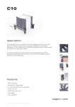
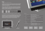
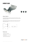
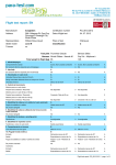
user guide
Origen
T12
26
m
m
Index
2
3
4
5
5
6
7
8
212 mm
T12 specifications
T12 overview
Connecting to your PC
TFT controls / menu operation
TFT menu guide
Touch panel software installation
VESA mount location
Optional T12 accessories
295 mm
93 mm
150 mm
Specifications
external dimensions
- 295x105x212mm (LxWxH) with a footprint of 150x93mm
IR support
- IR sensor compatible with IR221 & IR211
cable
- 5m umbilical (extendable)
connection
- breakout PCB to VGA, USB, IR and 12v power
compatibility
- Windows Vista / Linux / OSX
ports
- 2 x external USB 2.0*
construction materials
- aluminium
finish
- silver + black sandblast
wall mount
- VESA mountable (75x75mm) or with wall mount bracket (optional)
net weight
- 2.2kg
TFT specification
- 12.1" SVGA,16:10 ratio, 1280x800 native - 1920x1080 max, 12V DC
Thank you for purchasing this Origenae product. We recommend that you read thoroughly before use.
Origenae is not responsible for any damages due to external causes, including but not limited to, improper use,
problems with electrical power, accident, neglect, alteration, repair, improper installation or improper testing.
Copyright © 2008 Origenae Technology. All rights reserved. Revision T12.V1/02.08
2
T12 overview
12345678910 11 12 13 14 15 16 -
Aluminium TFT bezel
Stand release screw
IR/LED window
Air vent
Aluminium table stand
TFT control (see page 5)
TFT on/off button
12.1” touch screen TFT
Aluminum back housing
Air vent
USB 2.0 ports*
Umbilical port (T12)**
Internal break-out-box (iBOB)
Umbilical port (PC)**
VGA input
Umbilical cable
* For use with lower power devices (up to 100mA) such as iPods, cameras, USB
flash cards etc. Higher powered units may cause interference or become unstable.
1
9
2
3
5
4
10
5
6
7
11
2
** For safety reasons, only Origen umbilical cables with the
icon may be
connected to these ports. Serious damage may occur if the wrong cable is used.
8
12
14
13
15
16
3
Connecting the T12 to your PC
The T12 connects to your PC with a single [umbilical] cable. This plugs to a small internal breakout box (iBOB),
which separates the power, VGA, IR & USB to allow for standard connection. USB is taken from a USB header on the
motherboard. 12V power is taken from a spare MOLEX connecter on the power supply (PSU). Alternatively the iBOB
can be powered externally from a 12v dc supply. NEVER CONNECT TO BOTH POWER INPUTS AT THE SAME TIME.
A VGA feed is taken directly from your graphics card via the loop cable. If desired, iBOB can connect to either our
IR221 or IR211 controllers, making use of the built-in IR sensor and bypassing the one in your media centre PC.
External connection
Internal connection
External connection
1(umbilical) to T12 head-unit
2 - VGA IN - via loop cable
3 - Optional 12v IN (when not using MOLEX)
-
+
INPUT: 12V DC
2A
Internal connection
1 - MOLEX - 12v power (from PSU)
2 - Connects with IR211 or IR221 controllers
3 - USB to motherboard
4 - Spare USB headers
Pin-out reference
+5
GND
+12
GND
VCC
D–
D+
GND
VCC
GND
IR-OUT
LTR-C
LTR-E
VCC
D–
D+
GND
VGA
PC
USB
POWER
IR
The umbilical connects through a small breakout PCB fitted to an expansion slot in your PC
4
IR221
TFT controls / menu operation
TFT control buttons are located under the head unit.
The first 3 control the on-screen display (OSD) while
the larger button to the right powers the TFT on and off.
To adjust the TFT settings, press the menu/set button
( ) to bring up the OSD. Use the and buttons
to navigate through the 10 menu categories. Press the
button to select a category then where appropriate
use the and to increase or decrease the value as
desired. Press the
button again to confirm the setting
then repeat the process until you have made all the
required adjustments. To exit, simply locate the EXIT
category and press the
button, or after 10 seconds
of inactivity the OSD will exit automatically.
Auto adjust [short cut]
With the screen on, press and hold down the power
button ( ) for 5 seconds to engage the auto-adjust
function without having to access the OSD menu.
MENU/
SELECT
VALUE
DOWN/UP
TFT POWER
ON/OFF
OSD
The guide below shows the quickest route [in grey]
and the adjustment sequence [in orange] for each of
the OSD menu items (all assume you are not currently
in the menu, with the exception of EXIT).
Brightness.
Contrast.
1
V position.
5
Language
4
Phase.
2
Auto-adjust.
3
Clock.
3
Factory reset.
H position.
4
Exit.
2
5
Touch panel software installation
In order to use the touch panel, you must first install the TouchKit software from the install CD provided, or downloaded from
the support section on our website. If the CD does not boot automatically you may also begin the software installation by
double clicking on the setup.exe file which is located in the TouchKit folder.
1 After opening the setup.exe file, the
install will begin with the above prompt.
Click ‘Next’ to continue.
4 The touchscreen controller should
already be connected if you have
correctly connected all cables inside
your chassis. Click ‘OK’.
6
2 Ensure that ‘Install PS/2 interface
driver’ is not selected and click ‘Next’.
3 Select ‘None’ and click ‘Next’.
After completing the install, the
TouchKit software will allow you
to perform a 4-point calibration.
5 If you intend to use spaning mode
with multiple monitors, please select
‘Support Multi-Monitor Systems’. Click
‘Next’ to continue.
6 Change the TouchKit software
install folder if required and click
‘Next’ to continue.
7 Change the Program Folder name
if required and click ‘Next’ to continue.
x
1
8 Click ‘Yes’ to perform a 4 point
calibration. This is required for
proper touch screen operation.
9 The software will now scan and install
the touch screen device. The TouchKit
calibration procedure will follow.
10 To calibrate, press and hold down the X that blinks in the corner of the
screen until it disappears. Repeat this procedure with each of the 4 X’s that
appear. On completion, the touch screen will be calibrated and ready for use.
3
2
VESA mount hole location
To access the VESA fixing points (75x75mm) remove the
2 screws shown 1 . Unhook and lift away the main unit from
the desk stand 2 . The 4 mount holes are shown above 3 .
Only use M3 screws no more that 10mm in length.
7
Origen
10m umbilical cable with extender
This additional cable allows the
T12’s range to be increased
by a further 10 metres.
Ideal for larger rooms
or custom installs.
Optional accessories currently available for the T12
10m / 33ft
Global HQ
#209 Baeksan B/D
763-2 Hengsin-Dong
Dukyang-Gu
Goyang City
Gyounggi-Do
412-220 South Korea
Website
www.origenae.com
20mm
Steel wall mount (black)
To wall mount your unit, this steel
bracket is easily installed and is not
visible once the T12 is mounted.