1
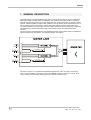
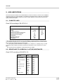
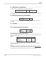
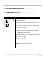
EN
OPD EXP
STO-SAFE TORQUE OFF
USER GUIDE
OPD EXP
SUMMARY 1 GENERAL DESCRIPTION ..................................................................... 2
2 USE LIMITATIONS ................................................................................. 3
2.1 2.2 2.3 2.4 2.5 CLIMATE CLASS ................................................................................................................. 3 RESISTANCE TO CHEMICALLY ACTIVE SUBSTANCES ................................................. 3 RESISTANCE TO VIBRATIONS .......................................................................................... 4 PROTECTION AND POLLUTION DEGREE ........................................................................ 4 STORAGE ............................................................................................................................ 4 2.5.1 2.5.2 Environmental Storage Conditions ................................................................................... 4 Recovery Procedure After Storage................................................................................... 4 3 ADJUSTMENT AND DRIVERs SUPPLY ................................................ 5
3.1 3.2 TERMINAL BOARD DESCRIPTION .................................................................................... 5 TERMINAL BOARD POSITIONS ......................................................................................... 7 4 EXTERNAL CONNECTIONS ................................................................. 9
5 DESCRIPTION OF STO OPERATION ON OPEN DRIVE.................... 10
5.1 5.2 ENABLING THE STO SYSTEM ......................................................................................... 10 DISABLING THE STO SYSTEM ........................................................................................ 11 6 DIAGNOSTIC SYSTEM ........................................................................ 12
6.1 6.2 BASIC DIAGNOSTIC ......................................................................................................... 12 INTELLIGENT DIAGNOSTIC ............................................................................................. 12 6.2.1 FB1 AND FB2 CONTROL .................................................................................................. 12 6.2.2 “NOT DANGEROUS FAILURE” LOGICAL OUTPUT CONTROL ...................................... 14 7 APPLICATION EXAMPLES .................................................................. 15
8 TECHNICAL DATA ............................................................................... 18
KEY TO SYMBOLS
Caution
Danger
STO (Safe Torque Off)
Rev. 1.3 – 30.11.11 - EN
1
OPD EXP
1 GENERAL DESCRIPTION
The OPEN DRIVE converter implements the Safe Torque Off (STO) system to prevent unexpected
starting according to the EN 61800-5-2 standards. This system prevents the creation of a rotating
magnetic field by disconnecting the control voltage from the power semiconductors. Thanks to these
systems, it will be possible to conduct short operations such as cleaning and/or maintenance work on
the non-electrical parts of the machine without disconnecting either the drive power supply or the
connection between power and engine. The STO system, therefore, will be managed by components
with limited power which means that the cost of the elements used in the switchboards will be
reduced.
The STO system is implemented using two redundant channels, each of which has its own feedback
signal accessible from the outside. The operating diagram is as follows:
The input to channel 1 is +24VDR and its feedback signal is STO_FB1. The input to channel 2 is
STO_2 and its feedback is STO_FB2. Each of the feedbacks refers to a clean N.C. contact which
can be read by an external logic managing the STO system at machine level.
2
STO (Safe Torque Off)
Rev. 1.3 – 30.11.11 - EN
OPD EXP
2 USE LIMITATIONS
The environmental constraints of the OPEN DRIVE converter are listed in a section of the installation
manual and refer to its normal operation. The following paragraphs serve to clarify the use limitations
of the converter with a view to making sure that its correct operation continues also when the STO
system has been activated.
2.1
CLIMATE CLASS
Class 3K3 according to EN 60721-3-3
Environmental parameter
Limits
working temperature (1)
humidity
atmospheric pressure
maximum surrounding air movement
maximum temperature gradient
maximum thermal irradiation
condensation
precipitation with wind
water other than rain
ice formation
0÷40
5÷85
70÷106 (2)
1
0.5
700
NO
NO (3)
NO
NO
Unit of
measuremen
t
°C
%
kPa
m/s
°C/min
W/m2
(1)
The climate class 3K3 includes a 5÷40°C use limitation, but the converter can work also if the
environmental temperature is 0°C. The maximum operating temperature of the converter reaches
45°C. In this case, declass the rated power to 88%.
(2)
The atmospheric pressure limitations correspond to a 0÷3000m a.s.l. operating range. In actual
fact, above 1000m it will be necessary to declass the rated power of the converter by 1% every
100m.
(3)
The converter must be installed in a switchboard and not outside.
2.2
RESISTANCE TO CHEMICALLY ACTIVE SUBSTANCES
Class 3C1R according to EN 60721-3-3
Environmental
parameter
sea salts
sulphur dioxide
hydrogen sulphide
chlorine
hydrochloric acid
hydrofluoric acid
ammonia
ozone
nitrogen oxide
STO (Safe Torque Off)
Rev. 1.3 – 30.11.11 - EN
Maximum
value
NO
0,01
0,0037
0,0015
0,001
0,001
0,00034
0,001
0,00066
0,001
0,0012
0,03
0,042
0,004
0,002
0,01
0,005
Unit
of
measurement
3
mg/m
3
cm /m3
mg/m3
cm3/m3
mg/m3
cm3/m3
mg/m3
cm3/m3
mg/m3
cm3/m3
mg/m3
cm3/m3
mg/m3
cm3/m3
mg/m3
cm3/m3
3
OPD EXP
2.3
RESISTANCE TO VIBRATIONS
As regards vibrations, the OPEN DRIVE has the following use limitations:
10Hz ≤ frequency ≤ 57Hz
57Hz ≤ frequency ≤ 150Hz
0.075
1
mm (width)
g
In the event of vibrations exceeding the limits indicated above, suitable reduction measures will have
to be adopted.
2.4
PROTECTION AND POLLUTION DEGREE
IP20
2 (1)
Protection degree
Pollution degree
(1)
Non-conductive pollution and – occasionally and temporarily – conductive pollution generated by
condensation.
2.5
STORAGE
2.5.1 Environmental Storage Conditions
temperature
humidity
condensation
-10÷60
5÷95
NO
°C
%
2.5.2 Recovery Procedure After Storage
The converter cannot be used immediately after a storage period. To avoid converter failures, use the
following recovery procedure.
PHASE 1:
Non-powered converter
temperature
15÷35
°C
humidity
5÷75
%
condensation
NO
Atmospheric pressure
86÷106
kPa
Recovery time (1)
1
h
(1)
After this recovery time, there must be no trace of condensation inside or outside the operation
(well—aired environment).
PHASE 2:
For long storage periods (one or more months) regenerate the electrolytic condensers of the power
bus. Feed the converter from the terminal boards L1, L2 and L3 for 30min-1 hour without letting it run.
Once the regeneration process has been completed, the converter can work normally.
4
STO (Safe Torque Off)
Rev. 1.3 – 30.11.11 - EN
OPD EXP
3 ADJUSTMENT AND DRIVERS SUPPLY
3.1
TERMINAL BOARD DESCRIPTION
The following tables list the terminal boards used to feed the OPEN DRIVE cards and to perform the
diagnostic work on the STO system.
X3
Pin
Name
1
+24V
2
0P
Adjustment card feeding
Description
+24V (22V÷26V) min. 600mA (OPD3-7-12-15A), min. 800mA (OPD22A),
min. 1A (OPD32-40-48-60A)
The terminal boards X3-1 and X3-2 power the adjustment card, the sensor in the
motor and the cooling fans of the radiator.
The power sizes 70A-150A generate inside them the +24V from the main supply.
Then, on terminal X3 is available a +24V that can used by the customer only for:
a)
b)
Provide the converter breakouts
Power the two STO function channels (the power must be interrupted by
appropriate safety contacts). In the power size 70A-150A is also possible to
feed the regulation board with an external +24V using the terminal X3: the
internal generated voltage and external provided voltage will not be in
conflict, but will be used the source with the higher voltage. This allows to:
a)
b)
Set the driver without feeding the power side
Keep alight the regulation part even if there isn’t the power supply.
The current absorbed by the drivers on the +24V terminal for the different sizes
are the follows:
OPDE 3-7-12-15A
min. 600mA
OPDE 22A
min. 800mA
OPDE 32-40-48-60A min. 1A
OPDE 70÷150A
min. 500mA
N.B. the pinout of X3 change in function of the drive size
STO (Safe Torque Off)
Rev. 1.3 – 30.11.11 - EN
5
OPD EXP
S1
Pin
Name
0P_DR
10
6
Description
+24V (22V÷26V) min. 200mA
Powering voltage for the first of the two STO safety system channels. This channel
powers the IGBT power drivers. When the drive is working normally, the +24V_DR
driver must be provided. On the other hand, to enable the STO system, it is
necessary to disconnect +24V_DR.
9
+24V_DR
8
STO_FB1_B
Clean N.C. contact max. 60Vdc max. 0.5A
7
STO_FB1_A
Monitor of the first STO system channel which indicates whether the IGBT drivers
are powered or not. When the terminal board1 is powered, the contact is open..
6
N.C.
5
0P_STO_2
4
STO_2
3
N.C.
2
STO_FB2_B
1
STO_FB2_A
No connect
+24V (22V÷26V) min. 40mA
Power voltage for the second of the two STO safety system channels. This
channel powers the relay which disconnects the IGBT driver controls. When the
drive is working normally the STO_2 must be powered. On the contrary, to enable
to STO system, it is necessary to disconnect STO_2.
No connect
Clean N.C. contact max. 60Vdc max. 0.5A
Monitor of the second STO system channel which indicates whether the relay
which disconnect the IGBT drivers are powered or not. When the terminal board is
powered, the contact is open
STO (Safe Torque Off)
Rev. 1.3 – 30.11.11 - EN
OPD EXP
3.2
TERMINAL BOARD POSITIONS
The X3 and S1 terminal boards are placed on the same side as the converter as shown in the figures
below
OPD SIZE. S
OPD SIZE. L
STO (Safe Torque Off)
Rev. 1.3 – 30.11.11 - EN
OPD SIZE. M
OPD SIZE. X
7
OPD EXP
CASE 1-2-3
8
STO (Safe Torque Off)
Rev. 1.3 – 30.11.11 - EN
OPD EXP
4 EXTERNAL CONNECTIONS
The following paragraphs provide indications about the OPEN DRIVE connection only as regards the
feeding of the adjustment card and STO safety system. For the remaining connections, please refer
to the OPD installation handbook.
As indicated in par. 3.1, the terminal board X3 can be powered by the adjustment card (+24V). On
the other hand, the terminal board S1, power the pilot drivers of the power IGBT and the relay which
carries the controls of the adjustment card to the drivers.
The signals +24V_DR (referring to 0P_DR) and STO_2 (referring to 0P_STO_2) each relate to one
channel of the STO safety system. For this reason it is particularly important to pay great attention
when cabling these signals from the OPEN DRIVE to the safety module used on the switchboard.
a) For the X3 connection use a screened two-way cable whose strap must be connected to the 0P
signal. Normally a screened cable is not required for adjustment powering. A screened cable is
chosen to make sure that, in the event of failure of the powering cables, the safety system is
disconnected. The reason is that:
the terminal board X3 is close to the terminal board S1;
the powering cables for X3 and those for S1 will reach the converter inside the same
conduit.
b) For the first channel connection (+24V_DR e 0P_DR) use a screened two-way cable whose
strap must be connected to the 0P_DR signal. A screened cable with the strap connected to
0P_DR serves to avoid disconnecting the safety system in the event of failure of the cables
outside the converter. An example of this is the loss of insulation and subsequent accidental
contact between one of the cables connected to 24V on the switchboard and +24V_DR.
c) For the second channel connection (STO_2 e 0P_STO_2) use a screened two-way cable whose
strap must be connected to the 0P_STO_2 signal. A screened cable with the strap connected to
the 0P_STO_2 serves to avoid disconnecting the safety system in the event of failure of the
cables outside the converter. An example of this is the loss of insulation and subsequent
accidental contact between one of the cables connected to 24V on the switchboard and the
STO_2 signal.
d) For the tow monitor connection, the type of cable to be used depends on how the diagnostic test
on the safety chain is conducted. Some safety modules do not specify the type of cable to
connect the signals used by the diagnostic system. The reason for this is that they are able to
determine themselves whether there is a failure in these connections. If the diagnostic test on
the safety channels is conducted directly by the manufacturer of the switchboard, it is necessary
to determine whether this test is able to detect a failure in the connection cables. In the
diagnostic test, failure of the monitor signal cables causes the test itself to fail. It is not possible
to determine where the failure is: on the safety chain or on the monitor. The use of screened twoway cable for each of the two monitor, therefore, makes it at least possible to rule out a failure of
the monitor signal connections
STO (Safe Torque Off)
Rev. 1.3 – 30.11.11 - EN
9
OPD EXP
5 DESCRIPTION OF STO OPERATION ON OPEN DRIVE
5.1
ENABLING THE STO SYSTEM
If the converter is working normally, that is to say the STO system is disabled, it is necessary to
power the +24V of the adjustment (X3), as well as +24VDR and STO_2. In this situation the clean
monitor contacts (STO_FB1 and STO_FB2) will both have to be open.
To enable the safety system follow this procedure:
a) stop the motor
(1) (2)
b) disconnect operation
c) disconnect +24V_DR (3)
(3)
d) disconnect STO_2
(1)
it is possible to carry out operations a) and b) only by disconnecting operation if the converter
settings include “stop at minimum speed” (C28=1). In this case the converter brings the motor to the
minimum speed (set to zero through the parameter P50) then disconnects operation.
(2)
in the presence of external influences (for example falling suspended loads), it might be necessary
to take extra precautions (for example mechanical brakes) to prevent any risk.
(3)
the sequence followed for items c) and d) is not relevant: for example the signals STO_2 and
+24V_DR can also be temporarily disconnected.
CAUTION: enabling the STO system while the machine is running causes total loss of motor control.
Enable the STO system only after its operation has been stopped following the procedure described
above.
DANGER: the terminal boards +, -, U, V, W, F remain live. No maintenance work must be conducted
and electrical component must not be touched.
CAUTION: after power has been disconnected, both channels take time to return to a safe condition.
The times are indicated below.
CHANNEL 1
CHANNEL 2
Maximum time after +24V_DR has been disconnected
Maximum time after STO_2 has been disconnected
1s
20ms
DANGER: on brushless motors with permanent magnets, in the event of simultaneous failure of the
two power switches, motor movement is possible up to 180° electrical equal to [180/n° polar motor
couples] mechanical degrees.
In this situation the feedback contacts (STO_FB1 and STO_FB2) will both have to be closed.
Any discrepancy in only one of the monitor contacts compared to the converter status indicate a
failure. In this case the safety system might not work correctly and needs to be immediately repaired.
Apart from the feedback contacts available outside, inside the OPEN DRIVE there is a feedback
signal (only for channel 1) used by the adjustment card to manage this situation.
When the connection “enable safety stop only as signal” is disabled (C73=0 which is the default
configuration), the converter indicates this status with the alarm presence A13 con d49=1. In this
situation the logic output o17 “power electronic card not supplied” switches to high, the logic output
o0 to low (the drive ready is disconnected) and the power insertion control is disconnected.
With the C73=1 connection, the converter still brings to a high level the logic output o17 “power
electronic card not powered”, the power insertion control is disconnected but no specific alarm is
generated and the logic output o0 “Drive ready” remains on high, that is to say the drive ready
remains active (if no other alarms are present).
10
STO (Safe Torque Off)
Rev. 1.3 – 30.11.11 - EN
OPD EXP
5.2
DISABLING THE STO SYSTEM
To disable the STO system it is sufficient to power again +24V_DR and STO_2. Also in this case the
sequence followed is not relevant.
CAUTION: From the moment the machine is powered, it takes time to disable the safety systems on both
channels. The times are indicated below
CHANNEL 1
CHANNEL 2
Maximum time after the enabling of +24V_DR
Maximum time after the enabling of STO_2
100ms
20ms OPDE 03÷60A
(4)
1.1s
OPDE 70÷150A
(4)
In the case of OPDE 70÷150A drivers with supply of the AC power side, for wich the customer has required a
precharge time of the power side higher than that standard, the maximum out time of safe function passes to:
OutSTO_maximum_time= 600ms+Riquired_precharge_time
In the standard configuration the precharge time is 500ms.
In this situation the feedback contacts (STO_FB1 ed STO_FB2) will both need to be open.
Any discrepancy in only one of the monitor contacts with respect to the converter status means that
there is a failure. In this case the safety system might not be working properly and it needs to be
repaired immediately.
In the case of the adjustment card, to return to the normal operation conditions it is necessary to do
the following.
C73=0
Wait at least 100ms after introducing +24V_DR, then enable the alarm reset. In this condition the o17
logic output “power electronic card not powered” reaches a low level. The o0 logic output “Drive
ready” is on high which means that the converter is ready to work.
C73=1
The converter behaves in the same way as with C73=0 except that it is not necessary to enable the
alarm reset.
ATTENTION: If the run command is given before the maximum time of out by STO function indicated
in Tab. 2, the driver shows the alarm A12 with d49=1 “run without precharge”.
STO (Safe Torque Off)
Rev. 1.3 – 30.11.11 - EN
11
OPD EXP
6 DIAGNOSTIC SYSTEM
When the safe function is active, the feedback signals indicate if the safe function has been executed
correctly . it is necessary to control these feedback signals, with the aim to distinguish between:
Basic diagnostic (compulsory);
Intelligent diagnostic (optional).
6.1
BASIC DIAGNOSTIC
The basic diagnostic is compulsory, then it has to be always executed, because it represents a basic
control for the correct working of STO function. To satisfy the basic diagnostic is necessary that:
a) The feedback signals and the digital output o23-“Not Dangerous Failure” are monitored at every
machine start, on which is mounted the drive. The machine start will be executed if the feedback
contacts STO_FB1 are STO_FB2 are both closed (feedback signals both “active”) and if the
output o23-“Not Dangerous Failure” is high;
b) The reset command, which brings out the machine from the state of “emergency stop”, is
enabled if during the state of emergency stop, the feedback contacts are both closed and the
digital output o23-“Not Dangerous Failure” is high.
See paragraph 7, for some examples of connections that satisfy these prescriptions.
6.2
INTELLIGENT DIAGNOSTIC
The intelligent diagnostic is optional and can be used if the STO function is controlled by a PLC or by
an other intelligent system. It consists to perform periodically:
a)
Two test sequences, one for each of the two channels, which allow to detect any failure of
the safety function before it is turned on (will be discussed later in FB1 and FB2 control);
b) A control of the logic output state o23- “Not Dangerous Failure (will be discussed later in
“Not Dangerous Failure” output logic control).
Below are described in detail the two controls.
6.2.1 FB1 AND FB2 CONTROL
Looking at the congruence between the feedback signals and the presence or absence of the control
voltage in input to the two channels of the STO, it’s possible run the control sequences that allow you
to detect some faults on safety channels.
CAUTION: The control sequences of the two safety channels must be performed one at a time and
not simultaneously.
The maximum time of entry and exit safe condition are shown in the following table.
These figures refer to the maximum time between the change in status, channel switching and
security of its monitor
CHANNEL 1
Maximum time between the +24V_DR interruption and STO_FB1 commutation
Maximum time between the +24V_DR insertion and the STO_FB1 commutation
Tab.3
CHANNEL 2
Maximum time between the STO_2 interruption and STO_FB2 commutation
Maximum time between STO_2 insertion and STO_FB2 commutation
1s
100ms
100ms
20ms OPDE
03÷60A100ms OPDE
70÷460A
Tab.4
12
STO (Safe Torque Off)
Rev. 1.3 – 30.11.11 - EN
OPD EXP
The sequence to be performed for channel 1 is represented by the following flow chart:
ATTENTION: For the OPDE 70÷150A sizes, the diagnostic function of channel 1 must be done with
the second safety channel in OFF (+24V present on input STO_2). For OPDE 03÷60A sizes,
instead, the state of the second channel of the safety function is not relevant.
FB1 control Flow-chart
The sequence to be performed for channel 2 is represented by the following flow chart:
ATTENTION: The state of the first channel of the safety function is irrelevant to the diagnostic test of
the second channel STO.
STO (Safe Torque Off)
Rev. 1.3 – 30.11.11 - EN
13
OPD EXP
Flow-chart FB2 control
If the diagnostic test detects a fault, the converter must be subjected to immediate repair, worth a
possible malfunction of the safety function in the subsequent request for intervention.
We recommend running these tests periodically in situations standstill. In any case it is required that
you also meet at least the basic requirements of diagnostics, namely a) and b) previously described
in section 6.1.
6.2.2 “NOT DANGEROUS FAILURE” LOGICAL OUTPUT CONTROL
The output control logic o23-"Not Dangerous Failure" allows to verify the presence of some
dangerous faults. To make the control is necessary to check that the logical output o23 is to a high
logical level keeping energized the channels 1 and 2.
See paragraph 7 for some examples that show how to connect the control output of this logic.
14
STO (Safe Torque Off)
Rev. 1.3 – 30.11.11 - EN
OPD EXP
7 APPLICATION EXAMPLES
The following are some application examples of the STO system. In the various examples the OPD
connector is linked to a safety module; regardless of the type of connection used, the safety module
must be set in order to have a controlled manual start and not an automatic start. Moreover the
feedback contacts must be connected in series to the reset button.
In this way the machine is started, and therefore operated, with the safety module on and it will be
mandatory to press the reset button to enable its starting. This is necessary in order to conduct, when
the machine is started, a test on the feedback signals.
For the proper use of feedback related to the digital-o23 “Not Dangerous Failure” o23 must be
configurated as an output physical logic associated with one of four logic outputs available. In order
it’s possible use the direct contact present in the clean logic output LO2 and LO4. In this case it’s
necessary configure the physical digital output with the direct logical output o23.
Alternatively, you can connect to each of the digital output, an external relay, with its contact placed
in series with the reset button. In this case, if the contact of the relay is n.c. then it’s necessary
configure the physical digital output with the denied logical output o23; But if the relay contact is n.o.
it’s necessary configure the digital output with direct logical output o23.
Example 1 illustrates the use of a Pilz PNOZ XV2 safety module which includes two relays each of
which has two immediate contacts and two timed contacts that are triggered after an adjustable
delay. One of the activated systems in the converter is “stop with minimum speed” (the connection
C28=1 needs to be set). If the emergency button is pressed, the start consent control is immediately
disconnected from the converter causing its controlled stop. The PLC is informed that the emergency
button has been pressed through the connection to its digital input. After a given delay, also the timed
contacts of the Pilz module are opened which enable the two channels of the STO system, only when
the motor has already been stopped. The delay time must be longer than the controlled stop time.
The feedback contacts of the STO systems are connected in series to the reset button which makes
it possible to leave the emergency stop condition. Therefore, resetting is enabled only if the feedback
contacts are closed at the same time as the STO system is enabled. If this does not happen, it
means that there a failure has occurred in the converter and the feedback contact will remain open.
This makes it possible to check the feedbacks of the STO system every time the machine is reset.
Warning: this example works correctly with the connection C73=0. To be able to go running, it’s
necessary provide a reset pulse alarm on terminal M1 on pin 1 (e.g. PLC). To exit by safe condition,
once you restore the security module, it’s necessary wait for the time indicated in Table 2 and then
provide the pulse for alarm reset.
STO (Safe Torque Off)
Rev. 1.3 – 30.11.11 - EN
15
OPD EXP
Example 1
Example 2 is a diagram where the operation is started by a field bus and therefore it is the
PLC itself which, having read the “emergency” signal, controls the converter to activate the
motor stop procedure. As is example 1, also in this case, the STO system is activated by the
timed contacts of the Pilz module.
WARNING: If the connection C73 = 0, to be able to go on run is necessary that the PLC provides a
command to reset alarms. To exit safe condition, once you restore the security module, you must
wait for the time indicated in Tab. 2, reset the alarm and then provide the run command SW (C21 =
1).
In case C73 = 1, the sequence to follow is the same as that for C73 = 0, but it is not necessary for the
PLC provides a command of reset alarms.
Example 3 shows an application where the PLC is able to read both the status of the incoming STO
signals and the feedback signals. This means that it is possible to conduct a regular check on the
PLC which compares the incoming status with the feedback status. If the PLC notices a discrepancy,
it means there is a failure which will be reported.
16
STO (Safe Torque Off)
Rev. 1.3 – 30.11.11 - EN
OPD EXP
Example 2
Example 3
STO (Safe Torque Off)
Rev. 1.3 – 30.11.11 - EN
17
OPD EXP
8 TECHNICAL DATA
The technical data change with the power sizes, because the used components change in the safety
channel.
EN 61800-5-2
OPDE 03÷60 A
SIL
2
PFH
8,4·10-8 h-1
Hardware Fault Tolerance
1
Lifetime
10 anni
OPDE 70÷150 A
2
2,8·10-8 h-1
1
10 anni
EN ISO 13849-1
OPDE 03÷60 A
d
3
39,6 anni
OPDE 70÷150 A
d
3
342,7 anni
PL
Categoria
MTTFd
18
STO (Safe Torque Off)
Rev. 1.3 – 30.11.11 - EN
OPD EXP
STO (Safe Torque Off)
Rev. 1.3 – 30.11.11 - EN
19
OPD EXP
20
STO (Safe Torque Off)
Rev. 1.3 – 30.11.11 - EN