1
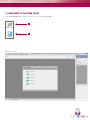
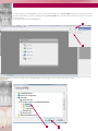
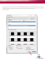
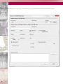
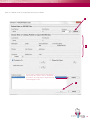
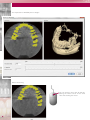
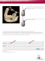
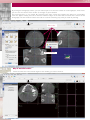
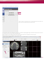
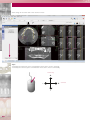
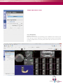
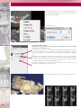
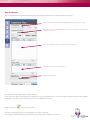
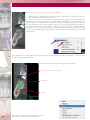
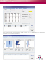
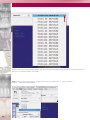
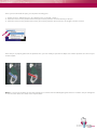
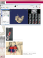
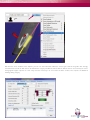
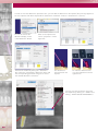
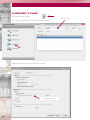
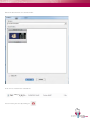
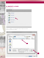
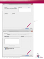
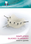
User’s guide
teknika3D software
A global solution for surgery
This manual’s purpose is to explain the different steps regarding the DEMO teknika3D software’s
installation. Please observe carefully these instructions for a good functioning of the software.
What is teknika3D ?
teknika3D is an advanced software of guided surgery diagnostics and treatment plan for
restoration of prosthesis on dental implant, based on pictures originating from tomography.
The software:
• Imports, organizes and stores CT pictures in DICOM format
• Presents and treats pictures using a large variety of tools
• Shows pictures in their original format
• Reformats pictures according to the maxillary or mandibular arch curves
• Allows to import and register radiographic guides
• Allows to import and register study models
• Allows to produce surgical guides based on the proposed implant planning
• Allows to print information about planning
SUMMARY
1) IMPORT A DICOM FILE
Page 3
2) CASE PLANNING
Page 10
Step 1. Radiographic guide/ Model
Page 14
Step 2. Volume reorientation and resize
Page 17
Step 3. Trace the arches
Page 18
Step 4. Add nerves / sinus
Page 21
4.1) Add nerves
4.2) Define the sinus
Step 5. Planning
Page 23
Step 6. Guided surgery guide
Page 31
3) SAVE A CASE
Page 32
4) SEARCH A PATIENT
Page 32
5) EXPORT A CASE
Page 34
6) IMPORT A CASE
Page 36
1) IMPORT A DICOM FILE
Start teknika3D double-clicking on Security server then teknika3D.
1
2
Software opening.
3
To start to import the DICOM files, click on “import DICOM” in the teknika3D tool bar. The command will not
be active if a patient’s scanner is already running. teknika3D does not allow to work with more than one scanner
running at once.
Insert a CD containing the DICOM files.
1
2
Select the folder of your CD/DVD player containing the slices (.dcm) then click on “OK”.
4
1
2
In this window, you can see a preview of the slices obtained in the selected file. As importation parameters, you can select a
reduced sample (1 slice out of 2 or 1 slice out of 3) to reduce the weight of the study. Use this option only in case loading the
complete case would use more than 1Go memory. In most cases, the “Skin segmentation” option is not necessary when it comes
to implantology, that is to say that the software will detect the skin and create a corresponding meshing.
Click on «IMPORT».
USER X
5
By clicking on the tab “import”, the program starts to read all the slices and opens the following window.
USER
6
X
Click on “validate”, fill in the empty fields and click on “NEW”.
1
USER
X
USER
X
User, X
}
2
If you select a patient that has already been
registered, this button will be activated, if
you click it, the study will be imported in the
selected patient’s file.
3
7
The importation of DICOM pictures begins.
Mouse functioning
You can change slices little by little by
placing the mouse cursor on the axial
slice and scrolling the wheel.
8
You can bring closer or backward the 3D picture by
placing the mouse cursor on the 3D view and scrolling
the wheel. You can move the 3D view by clicking and
maintaining the wheel.
You can turn the 3D picture by clicking on the 3D view
and holding the right click.
This window allows to specify the density threshold (in Hounsfield units) for the bone segmentation.
The software will automatically show a computed value, correcting itself following the editing and measure control criteria.
To define properly the threshold, slowly drag the cursor until the 3D vision makes appear some isolated points of soft tissue. It
is preferable to define a low threshold so that some points that are part of those soft tissues appear, rather than to define a high
threshold that may have some thin parts of the superior maxillary bone disappeared.
Click on “OK”.
The DICOM file importation is complete.
9
2) CASE PLANNING
The “Planning assistant” panel that we see is automatically open.
This assistant is divided in 6 steps
User
X
Utilisation
M
Tricks:
- To enlarge the views, click on the small + down on the left.
- To zoom, click right on the slice then on « ADJUST ALL ZOOM ».
Tools bar:
Save
Parameters
Full screen
10
Measure a
distance
Measure an
angle
Parameters:
For advanced users, some parameters can be optimized, such as:
Allows to select an implant by default
Minimum distance between two implants
Maximum angle between two implants
Minimum distance implant – nerve
Minimum distance between the sleeves
11
Before beginning the planning, you may have to clean some artifacts.
To do so, right click on the model and select “Edit mesh”.
User
X
Use the « PROJECTION » tool to delete a site and use the « RELATED REGION” tool to delete an area.
12
To delete a site, click on the site. It turns blue and then click on “Delete”.
Or you can also turn around the area with the cursor, finish with a double click on the start point. It turns blue and then click on
“delete”.
13
Step 1. Radiographic guide/ Model
The first step in teknika3D planning is to register the radiographic guide and/or the stone model.
This process is mandatory for cases for which you want a guided surgery and obtain a surgical guide. You can
register only the guide, only the stone model or both in the folder.
By selecting the option “radiographic guide or
model”, the options “load guide…”, “Segment
guide” and “load guide” activate.
Then, import the radiographic guide.
Tick this option if you do not wish to plan the case
to obtain then a surgical guide.
14
In case you used the double scan, click “radiographic guide or model”. The steps below correspond to the radiographic
guide importing and superimposing
Press the link command “Import guide”, the following window appears while doing so.
Select this option to import the axial slices of the radiographic guide.
1
2
3
The double scanner does that the radiology index will be carried out in the radiology center and normally provided with the same
CD/DVD containing the patient’s axial slices.
The radiographic guide and the axial slices are now scanned and registered in DICOM format. As a consequence, you have to click
on “Load DICOM file”. By doing so, a window appears so that you can select the file containing the axial slices of the radiographic
guide in DICOM format. By default, the selected file will be the last one you accessed. Select the CD/DVD player, open the file,
choose “radiographic guide” and click on “ok”.
The software starts reading the axial slices of the radiological guide, processes them and opens the following window.
User
Click on « Choose folder » if
you have not selected the right
folder that contains the axial
slices of the radiographic guide.
User^X prosthesis
Preview of the axial slices
contained in the selected folder.
With the vertical command
bar, you can go up or down to
preview all the slices.
Click on Import if the DICOM files
correspond to the radiographic
guide.
15
The program starts to analyze and treat the slices, a window allowing to view the guide opens.
Click on “ok”.
By default, the program detects the marked points automatically. The density value to detect the gutta-percha is
2500 HU. Click on “OK”.
16
The green-colored guide is then integrated to the model. You can now go to step 2.
In case you didn’t do a double scan and are only willing to do a simple planning, click “DO NOT PLAN A SURGICAL
GUIDE” and “NEXT”.
Step 2. Volume reorientation and resize
The patient is not always well oriented for the planning. In this step, we have the opportunity to reorientate the volume by correctly
reformatting the cross slices adapted to the planning.
In most cases, the patient’s scan includes areas that are useless to the planning; during this step, we can reduce the volume of
the interesting area for the planning, thus reducing significantly the space in mega octets that the study takes on the hard drive.
The volume can be reoriented by clicking on the tabs
of the panel, or by dragging directly the mouse on the
area we want to make turn.
By clicking on the tabs of the panel, you can do some
controlled rotations from 0,5° to 0,5° (value by default,
it can be modified on the panel). This technique is
slower but more controlled.
By dragging the mouse on the slices, you can do
interactive fast rotations, but less controlled.
Volume reorientation
As explained before, the tomographies realized on the patients include a field of view, normally
superior to the volume of interest, which is necessary for the planning.
These areas do not give any relevant clinical information, however they take physical space on the
hard drive.
17
By resizing the tomography volume, you can reduce by 8 to 10 times the number of used megabytes, what means
you can store 4 to 5 times more studies (in average) on your hard disk.
The resizing process is very simple. By encircling each axial, coronal and sagittal slice, blue lines surrounding
each slice appear. Initially, these lines mark the maximum edges of the cube that surrounds all the volume of the
tomography. The aim will be to reduce this cube to a volume containing only what you need for planning.
User
X
Bleu cube
Save changes
Step 3. Trace the arches
Locate the axial slice in the alveolar region of the maxillary you want to work on.
User
X
18
Click the button corresponding to the studied arch.
Now the software is waiting for you to start drawing the points of the arch. The
points of the arch will be traced on the axial section
Trace the points of the arch starting by an extremity, for example the right pterygoid region, and mark the points from the center to
the alveolar edge until arriving at the left pterygoid region.
With the wheel, you can change the axial slice in order to better look for the resorbed area’s alveolar region.
Double click the last point to finalize the arch and click “OK”
User
X
19
Same thing for the other arch. Then click on “Next”.
User
X
Tips:
-To modify the luminosity, press and hold the wheel, then, move it vertically.
-To modify the contrast, press and hold the wheel, then, move it horizontally.
luminosity
+
-
+
-
20
contrast
Step 4. Add nerves / sinus
4.1 ) Add nerves
Click on “Add nerve”.
Click then on the slice corresponding to the mandibular arch and trace the
nerve with the mouse. Start by an extremity, mark the points until another
extremity. Double-click on the last point to finish the arch. You can also use
the slices.
User
X
21
The diameter of the nerve is automatically defined at
2 mm. By clicking right on the nerve, you can access
this data and modify it.
«Propriety» tab
4.2 ) Define the sinus
The first step consists in defining the tomography limits which
envelop the maxillary sinus.
1- Click on the command “1.Volume limits”; some blue lines appear in the axial,
coronal and sagittal slices, they define the region enveloping the maxillary
sinus. Drag the lines in the different slices until they surround the maxillary
sinus.
2 - Mark a point inside the maxillary sinus that will be used as origin to detect
its volume. The algorithm starts from this point, takes its density and expands
in all the volume; the regions with an Hounsefield density in the area around
the specified tolerance will be segmented as sinus.
3 - Click on “Detect” to start the segmentation process. You can see the
segmented volume after a few seconds
We repeat this process in order to mark the left sinus.
22
Step 5. Planning
The left tab provides you with all the information concerning the implant system and the guide’s fixing pins.
Select the manufacturer and the guided surgery kit you are using.
The option 1 is activated by default, you will be able then to add more
treatment options.
List of the implants of the selected treatment option.
List of anchor pins to fix the guide.
Check the planning
You should first fully explore the maxillary anatomy.
You can use the arrow command of your keyboard to move the paraxial slices and view the bone anatomy and the case quantity
and quality. You can do some measurements of the available bone surface.
Click on the icon
and mark two points.
You can mark a point on the crest and another one at the nerve limit.
The software will calculate the distance between the two points and give you a result.
23
Once you have done this, you can place your implants.
1 - Select the tool « Add implant » by clicking on the « Operations » command (or you can
use the keyboard shortcut by clicking on “l”).
2 - Place the mouse on the paraxial slice where you want to place your implant platform.
By placing the cursor on the plier in the apical region and dragging it, you can increase the
implant length (if available by the manufacturer) holding the apex position. By placing the
cursor on the plier, in the central vestibular region, you increase the diameter of the implant.
3 - Place the mouse on the paraxial slice where you want to place your implant apex. By
moving the cursor to mark this position, the software will draw the implant outline according
to the list of available lengths and diameters of the model and according to the selected
manufacturer
Once the implant is correctly placed in the paraxial slice, you can modify its position to adapt it to a more suitable
position regarding the prosthesis.
You can change implant by clicking right on the implant.
3 : angle correction if necessary
1 : platform
2 : apex
24
Then clicking on “info”, you access the implant list.
You can then modify the selected implant.
You can also have information about the bone density around the implant. Click on the tab “Bone density”. The graphs show a
histogram of the internal and external implant density.
25
In some cases, the selected implant appears red. This is an alert informing you that you are too close to an anatomical
obstacle or to another implant for example.
Trick: to have a view centered on an implant, click left on the implant, then on the tab « VIEW »,
Click on « IMPLANT-AXIS LAYOUT»
26
Once you have finished this part, you can place the fixing pins.
1 - Select the tool « Add anchor pin » by clicking on the command « Action ».
2 - Place the mouse on the paraxial slice where you want to place the external extremity of the pin.
3 - Place the mouse on the paraxial slice where you want to place the apex of the pin (its length is fixed at 15 mm).
Once the pin is properly placed in the paraxial slice, you can modify its position to adapt it to a better position, the same way as
for the implant.
Note: it is necessary to place the axis of the fixing pin in contact with the radiological guide. If that is not done, the pin will appear
in red. The other alerts are similar to the implant alerts.
27
User
X
Implant too close to the nerve
Implant too close to another implant
In order to better see the implants and the
anatomical obstacles, you can remove the
bone. To do so, click on the tab “View”
and then untick “Show bone”.
28
User
X
Still from the “Info” window of the implant, you can see the information about the sleeve type used for the guide. We strongly
recommend to use RP or WP sleeves to facilitate the surgery. The RP+2, RP+4, WP+2, WP+4 sleeves are used only for cases
with gingival heights superior to 4 mm. They raise the sleeve by 2 or 4 mm from the bone surface. This requires an additional
thinking during surgery.
29
In order to view the abutment’s prosthetic axis, you can add an abutment on the implant (this part only applies to
the new implants with direct implant driver (Naturactis / Naturall+ / Natea+ / Aesthetica+² / Uneva+).
First of all, activate the
abutment display via the
“show abutment” button.
Click on the implant and
select « properties » with a
right click.
Go to the « abutment » tab.
Activate the module by ticking the « abutment »
box, select the “euroteknika_abutments” base and
the corresponding prosthetic range, then select
the wanted abutment’s reference.
The abutment is
then placed on the
implant
To make the abutment turn,
use your keyboard’s left and
right arrows.
You can view the panoramic X-ray with
the implants by clicking on « VIEW » then
ticking « X-RAY QUICK PANORAMIC ».
30
Step 6. Guided surgery guide
This step will be possible only if you have imported the DICOM files of the double scan.
Click on “Build surgical guide” then “Validate”.
1
2
31
3) SAVE A CASE
Click on the tab «SAVE».
The file is saved under c:/Nemotec/Nemotec Security Server/Filedata
4) SEARCH A PATIENT
Digit “*” in “Patient last name” and “Return” and select the patient by double-clicking.
Go to take the registered folder in “Go to”
then «DIAGNOSTIC FILES».
Select the folder you
want and double-click.
32
User
X
Your case appears on the screen.
User
X
33
5) EXPORT A CASE
To export your case, click on
Patient’s name
Then click on “Export cases” and enter the patient’s name
User X
User X
Select the file to save your case and click on “Finish”
Back-up directory
34
Select the document to save and click “OK”
Usuer X
A file .nmz is created in the selected file
User_X
You can leave your case by clicking on
35
6) IMPORT A CASE
Click on “Import cases”
Click on « SELECT » in the import file section or import case section
Select the file and click on “Open”
Usuer_X_11_05_305
1
User_X_11_05_30-51
2
36
User
X
Then click on
“next”
And click on “Finish”
UTILISATION M, Manuel
Go to the record in “Go to” then «DIAGNOSTIC FILES».
37
1
2
Select the record and double click
User X
Your case appears on the screen
User X
38
Notes
39
A global solution FOR SURGERY
euroteknika - teknika3D
726 rue du Général De Gaulle - 74700 SALLANCHES - France
Tel. 33 (0)4 50 91 49 20 - Fax : 33 (0)4 50 91 98 66
[email protected] - www.euroteknika.com - www.teknika-3d.com
MU-Logiciel_TK3D_GB_0514.