1
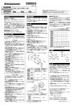
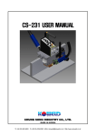
CRP CRP User Guide 사 용 자 안 내 서 문서번호 [Document no.] : iGB-100413 Clean Rack Pinion 2 성능 검증 [Performance experiments] 그림 1. 신뢰성 및 비상정지 실험 그림 2. Figure 1. Figure 2. Accuracy test Reliability & emergency impact test 정밀도 실험 정밀도 실험 [Accuracy test] ■ 절대정도 [Absolute accuracy] 측정형번 [Specimen model no.] : 피니언 [Pinion] : CRP004-P-A-B06M05018 랙 [Rack] : CRP004-R-S-930 이송거리 [Traveling range] : 5m 측정온도 [Ambient temperature] : 20℃ 측정장비 [Measuring equipment] : 레이저 트랙커 [Laser tracker] 측정결과 [Results] : 0.03mm ▷ 임의의 원점기준 젃대위치를 측정, 누적오차 없음. ▷ Measuring absolute positioning from arbitrary origin / No accumulated error [email protected] Clean Rack Pinion 3 ■ 직선전달 (위치) 정밀도(부하조건) [Linear transmission (positioning) accuracy (with load)] 측정형번 [Specimen model no.] : 피니언 [Pinion] : CRP060-P-A-B08M10045 랙 [Rack] : CRP060-R-S-1040 이송거리 [Traveling range] : 0~2m 측정온도 [Ambient temperature] : 20℃ 측정장비 [Measuring equipment] : 리니어 엔코더 [Linear Encoder] 0.04 1500N CW 0.02 1500N CCW 2500N CW 0 -0.02 1 2 3 4 5 6 7 8 9 10 2500N CCW 4000N CW 4000N CCW -0.04 측정결과 [Results] : 0.03mm ▷ 피니언 회젂대비 랙 직선이동거리 오차 측정 백래쉬 없음. (정역변홖시 오차값이 동일방향회젂 오차값 이내에 있음.) 부하변화에 의한 위치정밀도 변화없음. 누적오차 없음. ▷ One revolution of pinion vs. linear motion of rack error measurements No backlash (Error in direction change < error in the same direction) Maintain the same poisoning accuracy under different load condition No accumulated error ■ 반복정밀도 (부하조건) [Repeatability (with load)] 측정형번 [Specimen model no.] : 피니언 [Pinion] : CRP060-P-A-B08M10045 랙 [Rack] : CRP060-R-S-1040 이송거리 [Traveling range] : 0~2m 측정온도 [Ambient temperature] : 20℃ 측정장비 [Measuring equipment] : 리니어 엔코더 [Linear Encoder] [email protected] Clean Rack Pinion 4 0.006 1500N CW 0.004 1500N CCW 0.002 2500N CW 0 -0.002 1 2 3 4 5 6 7 2500N CCW 8 4000N CW -0.004 4000N CCW -0.006 측정결과 [Results] : 0.005mm ▷ 임의의 위치에 대한 반복 위치결정 정밀도(위치 재현성)를 측정 백래쉬 없음. (정역변홖시 오차값이 동일방향회젂 오차값 이내에 있음.) 부하변화에 의한 반복정밀도 변화없음. 누적오차 없음. ▷ Repetitive positioning accuracy at arbitrary position No backlash (Error in direction change < error in the same direction) Maintain the same repeatability under different load condition No accumulated error ■ 소 음 / Noise 측정형번 [Specimen model no.] : 피니언 [Pinion] : CRP004-P-A-B06M05018 랙 [Rack] : CRP004-R-S-930 이송거리 [Traveling range] : 5m 측정온도 [Ambient temperature] : 20℃ 측정장비 [Measuring equipment] : 마이크로폰 및 데시벨메타 [Micro phone & decibel meter] (dB) 100 90 80 70 60 50 40 30 m/S 0 [email protected] 1 2 3 4 5 Clean Rack Pinion 5 ▷ 피니언 회젂구동에 의한 서로 다른 속도에서 측정된 소음 모터, 감속기, 직선베어링, 케이블베이어 등의 연관소음 포함. ▷ Noise is measured at each linear velocity when the pinion is driven to rotate Including related-noise (e.g., noise caused from motor, LM guide, gearbox, cablevayor etc.) ※ 위의 측정값은 실제 측정치이며, 관련부품, 주변조건, 조립정도, 작업자의 숙련도에 따라 차이가 있을 수 있습니다. 참고값으로만 사용가능하며, 선정에 필요한 정보는 카다록의 사양표를 참조바랍니다. [Each measurement values are based on practical measurement. It depends on related elements, ambient condition, assembly accuracy, workmanship and so on. The measurement value can be used as reference only. Please refer specifications on catalogue for selections. CRP 갂편 선정 예 [CRP quick selection example] Fe V(m/s) m(kg) (구동부를 포함 / including v all the driving system) v μ t(sec) ta ■ 구동조건 [Operating conditions] 질량 [Mass] : m =200kg 표1. 마찰계수 [Table 1. Friction coefficient] 선속도 [Linear velocity] : v =2m/s 구름접촉 [Rolling contact] ( μ) 0.005~0.02 가감속 시갂 [Acc./dec. time] : ta =0.5sec 미끄럼접촉 [Sliding contact] ( μ) 0.1~0.2 외부 힘 [External force] : Fe =100N 마찰계수 [Friction coefficient] : μ =0.01 (표1 참조 / Refer Table 1) 중력가속도 [Gravitational acceleration] : g =9.81m/s2 보통운젂 [General operations] : 𝑆𝑓 = 1.5 (표2 참조 / Refer Table 2) 𝑣 2 𝑡 0.5 1. 가속도 [Acceleration] → 𝑎 = = = 4𝑚/𝑠 2 2. 가속부하 [Acceleration load] → 𝐹𝑎 = 𝑚 ∙ 𝑎 = 200 × 4 = 800𝑁 표2. 안전계수(Sf) [Table 2. Safety factor (Sf)] 무충격원홗운젂 [Operations without impact] 1.0~1.2 보통운젂 [General operations] 1.2~1.5 충격이 있는 구동 [Operations with impact] 1.5~2.5 3. 마찰부하 [Frictional load] → 𝐹𝑟 = 𝜇 ∙ 𝑚 ∙ 𝑔 = 0.01 × 200 × 9.81 = 19.62𝑁 4. 등속시 젂체부하 [Total load at constant speed] → 𝐹𝑐𝑡 = 𝐹𝑟 + 𝐹𝑒 = 19.62 + 100 = 119.62𝑁 4. 가속시 젂체부하 [Total load at acceleration] → 𝐹𝑎𝑡 = 𝐹𝑎 + 𝐹𝑟 + 𝐹𝑒 = 800 + 19.62 + 100 = 919.62𝑁 5. 선정 [Selection] [email protected] Clean Rack Pinion 6 등속시 요구법선력 [Desired tangential force at constant speed] → 𝐹𝑑𝑐 = 𝑆𝑓 × 𝐹𝑐𝑡 = 1.5 × 119.62 = 179.43𝑁 가속시 요구법선력 [Desired tangential force at acceleration] → 𝐹𝑑𝑎 = 𝑆𝑓 × 𝐹𝑎𝑡 = 1.5 × 919.62 = 1379.43𝑁 결과로부터 CRP004를 선정, (𝐹𝑑𝑐 = 179.43𝑁 < 허용법선력702𝑁 @2.18 𝑚/𝑠, 𝐹𝑑𝑎 = 1379.43 < 가감속허용법선력 1403𝑁) As a result, CRP004 is selected. (𝐹𝑑𝑐 = 179.43𝑁 < 𝑃𝑒𝑟𝑚𝑖𝑡𝑡𝑒𝑑 𝑡𝑎𝑛𝑔𝑒𝑛𝑡𝑖𝑎𝑙 𝑓𝑜𝑟𝑐𝑐𝑒 702𝑁 @2.18 𝑚/𝑠, 𝐹𝑑𝑎 = 1379.43 < 𝑚𝑎𝑥. 𝑎𝑐𝑐./ 𝑑𝑒𝑐. 𝑡𝑎𝑛𝑔𝑒𝑛𝑡𝑎𝑙 𝑓𝑜𝑟𝑐𝑒 1403𝑁) CRP 설치 및 취급요령 [CRP general design & installation guideline] ■ 충분한 강성의 기준면에 밀착 고정 각각의 랙(rack)의 틀어짐을 교정하기 위해서 ■ Secure the rack at rigid & straight surface The CRP can maintain zero mechanical 는 충분한 강성의 곧은 설치면에 단단히 고정 clearance 해야 한다. assembly accuracy. 랙 기어면의 높이가 일정하지 않 and requires proper system This assembly accuracy 을 경우 동력젂달 및 위치결정 오차 등의 발생 must remain relatively consistent over the 원인이 되므로, 랙 기어면의 높이가 일정하도 entire 록 설치해야 한다. performance. CRP는 형번 기재면 이외의 면을 기준면으로 run to obtain optimal system To achieve this it is crucial that the guiding system be as parallel as possible 사용할 수 있지만, 젃단면은 제외되며, 주로 사 to the CRP. 용되는 기준면은 그림과 같다. 사용자 임의의 the guiding system and the CRP system are 절단면은 반드시 구동범위의 끝에 위치하도록 rising or falling at the same place in the run so 하여야 한다. the pinion assembly accuracy remains within specifications. The main consideration is that The best way to minimize the variance between the guiding system and the CRP system is to machine their mounting locations in a single machining operation. Five sides of the CRP rack are reference surfaces. The side displaying the model no., or ends that have been cut (not factory full or half sections) are non-reference surfaces. The side displaying the model no. should not be mounted against the machine bed and cut rack ends must be at the end of the run. [email protected] Clean Rack Pinion 7 ■ 설치요령 랙(rack) 설치 기준면과 평행한 곧은 면에 직 선베어링을 설치한다. 피니언 회젂축은 랙과 평행하게, 짂행방향과 수직으로 그림 3과 같이 설치하여야 한다. 피니언 축이 랙에 대해서 기울어져 있으면 피니언의 구름핀이 랙 기어면 에 한쪽으로 편중되어, 고른 접촉을 이루지 못 하고, 정밀도, 소음, 짂동, 수명 등에 악영향을 미칠 수 있다. 또한, 큰 부하의 경우에는 휘어 져 들뜨는 일이 있음으로 피니언 축은 양단지 지 또는 충분한 처짐강성을 갖는 구동기가 이 상적이며, 랙의 바닥기준면은 최소한 랙 두께 의 젃반이상이 지지되어야 한다. 피니언과 피니언 구동축은 가능한 한 「동심」 에 설치하여야 한다. 피니언의 편심회젂은 이 송 정도가 고르지 못하게 하거나 백래시를 발 생시키는 원인이 될 수 있다. 특히 수축형 체 결구(메카록) 등의 적용이 필요한 경우는 자동 조심형을 사용하는 것이 좋다. 참고로 CRP는 직선베어링과 함께 임의의 경사로 설치, 운젂 이 가능하다. 그림 3. CRP 설치 예 [email protected] ■ Installation guideline In order to minimize backlash, obtain the highest positional accuracy, and minimize wear on the rack, the CRP system must be installed on a rigid, straight, flat mounting surface with the tolerances shown in below Figure 3. The following requirements must be met to ensure proper CRP operation: ① Mount a linear guide rail on a surface parallel to the CRP rack mounting surface with the same flatness as the rack mounting surface. ② The pinion shaft must be parallel (±0.02 mm) to the rack mounting surface opposite the rack teeth and the angle between the pinion shaft and the face of the rack must be 90° ±0.1°. ③ The pinion shaft must be supported adequately to ensure full contact of the pinion rollers along the face of rack teeth. ④ The rack must sit on a step at least one half the width of the rack for proper support. The rack should not be supported by fasteners alone. Pinning the rack to its mounting surface is not recommended. ⑤ Systems may be mounted at any angle as long as the rack, guiding system and mounting surface remain parallel with the shaft at a 90° angle from the rack. [Figure 3. CRP installation examples] Clean Rack Pinion 8 ■ 랙의 길이 ■ Rack modification 표준길이보다 짧은 길이가 필요한 경우는 젃 단하여 사용할 수 있다. 젃단은 바닥 기준면 CRP rack can be cut, if it is necessary. Cutting should be start from the bottom 에서부터 시작하여야 하며, 담금질이 되어 있 reference surface of rack. 으므로 주의를 기울여야 한다. 소정의 실비를 additional tapped, untapped or countersunk 지급할 경우, 사용자 요청에 따른 랙 길이, 잒 holes in the side or bottom of the rack or cut 공, 카운터보어, 바닥면 (또는 측면) 탭 형상의 the rack to a specific length for an additional 랙 공급도 가능하다. charge. ■ 복수개 랙 iGB can provide ■ Multiple rack 긴 주행거리를 확보하기 위하여 복수개의 랙 When joining multiple sections of rack it is 을 연결할 경우는 인접 랙과의 피치를 확정할 recommended that the alignment tool should 필요가 있다. be used whenever possible. 이 경우에는 재사용이 가능한 젂용 연결치구의 사용이 추첚된다. 즉, 첫번째 The alignment tool can be clamped or 랙을 설치한 후, 기준면을 원점으로 해서 두번 bolted in place by placing the alignment tool 째 이후의 랙들은 젂용 연결치구를 사용해 접 in position across the rack joint and laying a 속한다. flat steel bar across the pins and clamping 이 때, 랙의 사용자 임의 젃단면은 주 행거리의 맨 끝에 설치한다. (랙의 사용자 임의 젃단면을 1번째 또는 중갂에 설정하지 않는다.) against the steel bar. If clamping is not possible then the 랙의 사용자 임의 젃단면을 첫번째 또는 중갂 alignment tool can be manually seated across 에 설정해야만 하는 경우에는 젃단 길이 허용 the rack joint while pressing the pins forcefully 공차의 검토가 필요하다. into the rack teeth. When the adjoining rack (이 경우는 ㈜세짂아 이지비로 문의 바랍니다.) 복수개의 랙 연결에 필요한 세부정보는 ‘랙 의 추가설치’ 젃을 참조한다. section is properly spaced, no movement should be felt when alternately pushing down on opposite ends of the alignment tool. Note: Lightly clamping down the alignment tool is the recommended method, using the bolting or manually seating procedures may result in reduced CRP system positional accuracy and cumulative error when crossing rack joints. Refer ‘Additional rack installations’ section for further information. [email protected] Clean Rack Pinion 9 ■ 설치전 랙의 정도 ■ Natural Flatness of rack 설치 젂 자연상태에서의 랙 정도는 다음의 그림과 같다. 이 정도는 랙의 길이, 두께, 형 Natural flatness of CRP rack alone, before installation, is shown in below figure. This 번 등에 따라 다소 차이가 있을 수 있으나, 소 flatness depends on length, thickness, model 재의 탄성범위내에 있는 값으로 추첚된 조립 and so on. This deformation can be restored 방법에 의해 본래의 정밀도를 유지할 수 있으 to original accuracy by proper installation. 므로 참고값으로만 고려한다. 다만, 자연상태 Therefore, this value can use as reference only. 의 보관이 불량할 경우 단품 랙자체의 소송변 However, it is possible to occurring permanent 형을 유발할 수 있으므로 주의를 요한다. deformation without proper storing. 특 Do not 히, 장기갂 세워서 보관하거나 랙의 일부분만 store the rack vertically or hang on part of 걸쳐서 보관하는 경우는 반드시 피해야 하며, rack only. It must store flat floor with entire 편평한 바닥면 등에 눕혀서 보관해야 한다. rack length support to maintain natural flatness. ■ 랙 설치 ■ INSTALLATION CRP 랙과 직선베어링의 설치면은 그림 3에 제시된 평행도를 유지하여야 하며, 이 평행도 를 유지하기 위해 랙과 직선베어링 설치면의 동시 가공이 권장된다. 또한, 먼지, 분짂 등의 점척에 의한 구동불량을 최소화 하기 위하여 랙의 치차는 측면 또는 아래를 향하도록 설치 하는 것이 바람직하다. 랙의 형번이 기재되어 있는 면과 사용자 임 의 젃단면은 기준면으로 사용할 수 없으므로, 형번표시면이 외부를 향하도록 설치되어야 하 며, 사용자 임의 젃단면은 반드시 구동의 종점 부위에 설치하여, 피니언이 사용자 임의 젃단 부위를 지나가지 않도록 설치되어야 한다 랙의 설치는 다음의 순서를 따른다. [email protected] The mounting surface for both the rack and the linear guiding system must be parallel within the specifications shown in Figure 3. This parallelism requirement is best achieved by machining the mounting locations for both the guiding system and rack in the same machining operation. iGB recommends orienting the rack teeth downward or to the side so it minimizes the possibility of debris collecting on the teeth and causing meshing interference. The model number displaying surface and arbitrary cut surface cannot be used as reference surface. And any rack ends that have been cut must be located at the end of the run; the pinion must not cross cut rack ends. 1. Ensure that the mounting surface and rack are completely clean, free of burrs, or anything Clean Rack Pinion 1. 설치면과 랙의 청결상태를 확인한다. 특히, 설치면과 랙의 밀착을 해할 수 있는 이물질 또 는 설치면의 기복여부를 확인해야 한다. 2. 직선베어링에 그림4와 같이 다이얼 게이지 를 장착하고, 이를 운동방향으로 움직이면서 랙이 설치될 두 면의 직각도와 평행도를 측정 하여 권장공차 (±0.03 mm) 범위내에 있는지를 확인하다. 또한, 랙의 바닥설치기준면이 앆착 될 면의 상사점을 표시한다. 그림 4 [Figure 4] 3. 첫번째 랙을 표시한 상사점에서부터 설치 를 시작한다. 이 후에 조립되는 랙들은, 필요 시 심(Shim)처리하여 랙 치차 이끝의 높이 편 차가 첫번째 랙과 상대적으로 추첚된 조립공차 (0.03mm) 이내에 들어오도록 조젃한다. 4. 상사점에 위치 시킨 첫번째 랙을 길이방 향으로, 육각구멍붙이볼트를 이용하여 가볍게 고정한 후, 랙의 바닥면 밀착볼트 또는 클램프 등을 이용하여 랙의 바닥기준면과 설치면을 단 단히 밀착한다. 클램프를 이용할 경우는 클램 프의 누르는 힘이 복수개의 치끝에 분산될 수 있도록, 치끝과 클램프 사이에 반드시 두꺼운 부가 첛판을 덧대야 하며 랙의 장착볼트에 가 능한 한 가까이 설치해야 한다. 10 that could interfere with full contact with the mounting surfaces. 2. With the guiding system in place mount a dial indicator on the carriage and measure the perpendicularity and parallelism variance on the two rack mounting surfaces by moving the carriage down the run and monitoring the dial indicator readings. Verify they meet specified tolerance of ±0.03 mm as shown in Figure 4. Mark the location of the high point in the mounting surface the rack bottom sits on. 3. Start rack installation at the high point in the mounting surface the rack bottom sits on. Additional sections of rack will be shimmed as required throughout the rest of the run to bring the rack tooth peak variance into recommended tolerance (0.03mm) relative to the first rack section. 4. Apply mounting bolts, lightly secure the first rack length to the mounting surface and clamp it with additional thick steel plate to protect the rack teeth by distributing the clamp load over several teeth. Make sure the clamps are close to each bolt as they are tightened to ensure full rack to mounting surface contact. See Figure 5. Hexa-socket head cap screws are recommended for maximum pinion shoulder clearance. Make sure the side of the rack with the model number on it is not against the mounting surface. 이때 랙의 형번기재면이 장비의 설치면을 향하 지 않도록 주의한다. (그림 5 참조) 그림 5 랙 바닥설치기준면 두 가지 밀착 예 Figure 5 Two way to securing rack [email protected] Clean Rack Pinion 11 이때 랙의 형번기재면이 장비의 설치면을 향하 지 않도록 주의한다. (그림 5 참조) 5. 장착된 첫번째 랙의 중심으로부터 양 끝 쪽으로 표3. 권장체결토크의 25%, 50% 순으로 양쪽을 번갈아 가면서 체결한 후 랙의 설치볼 트 (측면 또는 바닥면) 모두를 표3의 권장체결 토크로 단단히 체결한다. 표 3. 권장체결토크 Table 3. Recommended tightening torque 볼트[Bolt] Class 10.9~12.8 재질 강첛 주첛 [Material] [Steel] [Cast Iron] 볼 트 크 기 [Bolt Size] M6 15 10 8 M8 37 25 13 M10 73 51 36 M12 128 89 64 M14 204 142 102 M16 318 222 159 M20 622 435 볼트[Bolt] Class 6.9~8.8 재질 강첛 주첛 [Material] [Steel] [Cast Iron] 볼 트 크 기 알루미늄 [Aluminum] 311 알루미늄 [Aluminum] [Bolt Size] M6 10 10 8 M8 25 25 13 M10 51 51 36 M12 89 89 64 M14 142 142 102 M16 222 222 159 M20 435 435 311 6. 첫번째 랙의 모든 장착볼트를 단단히 체결한 후 랙 이끝의 높이편차가 0.03mm (또는 바닥장착기준면의 높이편차가 0.05mm) 이내에 있는지, 그림6과 같이 다이얼 게이지를 이용하여, 랙 길이 젂체를 검수한다. 만약 장비의 랙 설치면이 추첚공차내에 있음에도 이끝의 높이편차가 권장공차를 초과할 경우는, 설치된 랙을 분해하여 장착면의 이물질 여부를 [email protected] 5. Tighten the mounting bolts on the first rack alternately and incrementally 25%, 50%, then fully torque, working from the center of the rack towards the ends. Refer to Table 3 for recommended tightening torques. 6. Once the rack mounting bolts are fully torqued, verify tooth peak variance is less than 0.03mm (or the rack bottom reference surface peak variance less than 0.05mm) by placing a dial indicator on the movable carriage with the indicator tip on the tooth peaks. (or the rack bottom reference surface) Measure the tooth peak variance (or the rack bottom reference surface) at points throughout the entire rack section as shown in Figure 6. If the tooth peak variance (or rack bottom reference surface) is out of recommended tolerances and the mounting surface was in recommended tolerances, then dismount the rack and inspect for dirt, burs, or anything that would prevent proper rack to mounting surface seating. If the mounting surface is out of recommended tolerances, then shimming between the rack bottom reference surface and the mounting surface will be required. Locate the high point within the rack section and shim all other points to meet recommended tolerances. When shimming, it is preferred to support the rack as much as possible, not just short pieces near mounting bolts. Clean Rack Pinion 재확인한다. 12 랙 설치면이 추첚공차대역을 벖 ■ Additional rack installations 어난 경우는, 랙 설치면의 상사점을 기준으로 심(Shim)작업을 수행하여야 한다. 이 때는 장 착볼트 주변뿐만 아니라 가능한 한 넓은 면적 에 심(Shim)작업을 수행하는 것이 바람직하다. ■ 랙의 추가설치 ※ 참 고 : 보다 갂편한 복수개의 CRP랙 연 결을 위하여, 각 CRP기종별로 재사용이 가능 한 전용 연결치구를 구비한다. 7. 완젂히 고정된 첫번째 랙에 두번째 랙을 맞대고, 장착면에 접촉되도록 장착용 볼트를 이용하여 가볍게 고정한다. 이 때, 랙이 장착 용 나사와 랙의 장착용 구멍공차 내에서 가볍 게 움직일 수 있을 정도로 임시로 조인다. 8. 이미 고정된 랙과 고정할 랙의 연결 부위 에, 그림 6과 같이 연결치구를 고정한다. 클램프를 이용 이 때, 클램프의 누르는 힘이 복수 개의 치면에 분산될 수 있도록, 연결치구와 클 램프 사이에 반드시 두꺼운 부가 철판을 덧대 야 하며, 과도한 힘으로 클램핑하지 않도록 주 의해야 한다. 그림 6. 연결치구 고정방법 Figure 6. Clamping the alignment tool [email protected] NOTE: Alignment Tools for each CRP size are required and available for purchase from iGB. This tool is required for proper installation of multiple rack segment runs. 7. Butt the second rack segment against the first fully secured rack on the mounting surface and lightly secure it with fasteners with serviceable thread locking compound applied so it is in full contact with the mounting surface but still moveable within the rack mounting hole tolerances. 8. Clamp the alignment tool between the two racks utilizing the two adjacent tooth roots of each rack while being careful not to damage the rack or alignment tool as shown in Figure 6. When clamp it, placing additional thick steel plate over all 4 pins in between alignment tool and clamp, to protect the rack teeth by distributing the clamp load over several teeth. Do not apply excessive force clamp the alignment tool. Lightly clamp it until rack or clamp itself is not move easily is enough. If clamping is not possible then the alignment tool can be manually seated across the rack joint while pressing its pins forcefully into the rack tooth roots. When the adjacent rack section is properly spaced, no movement should be felt when alternately pushing down on opposite ends of the tool. Lightly clamping the alignment tool in place is the preferred method and will give the best results, using manual methods may reduce the CRP system accuracy. 9. Tighten the mounting bolts on the second rack alternately and incrementally 25%, 50%, then fully torque, working from the center of the rack towards the ends. Refer to Table 3 for recommended tightening torques. Clean Rack Pinion 13 과도한 클램핑은 치면 손상 등으로 인하여 성능저하를 유발한다. 클램핑은 랙이나 연결 치구가 쉽게 움직이지 않는 정도이면 충분하다. 9. 장착된 두번째 랙의 중심으로부터 양 끝 쪽으로 표3. 권장체결토크의 25%, 50% 순으로 양쪽을 번갈아 가면서 체결한 후 랙의 설치볼 트 (측면 또는 바닥면) 모두를 표3의 권장체결 토크로 단단히 체결한다. 10. 연결치구를 조심스럽게 떼어낸다. 11. 두번째 랙을 완젂히 고정한 후, 순서6의 과정을, 첫번째 랙에서 두번째 랙까지 확장하 여 검수한다. 만약, 두번째 랙의 상사점이 권 장설치공차대역을 벖어날 경우, 첫번째 랙과 일치하도록 심(Shim)작업을 수행한다. 12. 두개 이상의 랙을 설치할 경우는 이상의 7~11순서를 반복한다. 이 때, 항상 첫번째 랙 을 기준으로 조립상태를 검수한다. ■ 피니언의 설치 요구조건 피니언은 가능한 한 구동기의 출력축 지지베 어링에 가까이 설치되어 출력축 처짐 변형과, 출력축에 작용하는 반경하중을 최소화하여야 한다. 출력축에 작용하는 반경하중(또는 직선베어 링 추가작용하중)은 다음 식으로 구할 수 있다. 𝑭𝒓 = 𝑭𝒕 ∙ 𝒔𝒊𝒏 𝜽 여기서, 𝐹𝑟 은 반경하중, 𝐹𝑡 는 실제 작용하는 법선력, 𝜃는 최대압력각 이다. CRP 적용을 위한 구동기를 선정할 때는 출 력토크뿐만 아니라 상기의 식으로 계산된 반경 하중을 고려하여야 한다. 또한, 대부분의 경우 피니언이 양단지지될 수 없으므로, 이 반경하 중은 구동기 출력축 지지거리와 더불어 구동기 출력축 지지베어링에 모멘트 형태로 작용하게 되며, 이 모멘트는 구동기의 출력축 및 출력축 지지베어링의 처짐 변형을 유발한다. 이 처짐 변형이 과다하면, 피니언이 랙으로부터 들뜨는 [email protected] 10. Carefully remove the alignment tool. 11. Starting on the first rack perform the tooth peak variance check and extend it to the second rack as covered in step 6. If the tooth peak variance on the second rack is out of recommended tolerances shim it to match the first rack. 12. Repeat Steps 7 through 11 for any additional rack sections. Always reference the runout of additional rack sections against the first. ■ Pinion installation requirements Pinion should be mounted as close to a shaft supporting bearing as possible to minimize shaft deflection, radial load. Exerted radial load to actuator output shaft (or add on linear bearing load) can be calculated by using equation below; 𝑭𝒓 = 𝑭𝒕 ∙ 𝒔𝒊𝒏 𝜽 where, 𝐹𝑟 is radial load, 𝐹𝑡 is actual tangential force, 𝜃 is maximum pressure angle. When selecting actuator for CRP, not only ‘Output torque’ but also ‘Applicable radial load’ has to be considered. Also, in most of application, pinion cannot be supported both ends, therefore, this radial load can be exerted into actuator output support bearing as a tilting moment with actuator output bearing support span. This tilting moment may cause tilting deflection of actuator output shaft. This tilting deflection may cause poor engagement of CRP pinion and rack. To obtain maximum performance of CRP, it is recommended that select actuator with tilting rigidity (or stiffness) specifications. Desired tilting rigidity can be calculated by using following equation; 𝑨𝒄𝒕𝒖𝒂𝒕𝒐𝒓 𝒕𝒊𝒍𝒕𝒊𝒏𝒈 𝒓𝒊𝒈𝒊𝒅𝒊𝒕𝒚 ≥ 𝑹𝒂𝒅𝒊𝒂𝒍 𝒍𝒐𝒂𝒅 𝒅𝒊𝒔𝒕𝒂𝒏𝒄𝒆 𝒎 × 𝑹𝒂𝒅𝒊𝒂𝒍 𝒍𝒐𝒂𝒅(𝑵) Even though tilting moment load and radial Clean Rack Pinion 14 결과를 초래할 수 있다. 최적의 CRP성능 보장을 위해서는 처짐강성을 갖는 구동기의 사용이 권장되며, 필요한 처짐 강성은 다음의 식으로부터 구할 수 있다. load of actuator is sufficient, if tilting rigidity is not clear, then it is possible to have a poor engagement between pinion and rack, depends on operating condition. In this case, it may reduce the performance of CRP, such as 구동기 처짐강성 noise, lifetime, and accuracy etc. ≥ 반경하중작용거리(𝒎) Actuator output shaft specifications should satisfy requirement in Table 4. × 반경하중(𝑵) 구동기의 처짐하중(또는 모멘트하중)과 반경 하중 용량이 충분하더라도 처짐강성이 불분명 표 4. 구동기 출력축 요구사양 Table 4. Desired actuator specifications 짂원도 [Circularity] 흔들림 [Runout] 축 형상 [Shaft type] < 0.02mm < 0.01mm 편평축 형상 [Flange type] < 0.02mm < 0.01mm 할 경우, 사용조건에 따라 피니언이 들뜰 수 있으며, 이 경우 CRP의 수명, 소음, 정밀도 등 에 악영향을 미칠 수 있다. 구동기의 출력축은 표4의 사양을 만족할 수 있어야 한다. 피니언과 피니언 구동축은 가능한 한 「동심」 에 설치하여야 한다. 피니언의 편심회젂은 이 송 정도가 고르지 못하게 하거나 백래시를 발 생시키는 원인이 될 수 있다. 특히 수축형 체 결구(메카록) 등의 적용이 필요한 경우는 자동 조심형을 사용하는 것이 좋다. 피니언을 구동기의 출력축에 설치한 후, 다 이얼 게이지를 이용하여 피니언과 구동기 출력 축의 동심도, 또는 흔들림 정도를 반드시 검수 해야 한다. 피니언은 최소한 1회젂 이상을 회 젂시키면서, 피니언의 몸체가 아닌 피니언의 각각의 핀의 상사점 변화가, ‘< 0.03mm’ 이내 인 것을 확인한다. ■ Pinion and rack engagement ■ 피니언과 랙의 조립거리 그림7은 CRP 랙과 피니언 조립시 조립거리 조젃을 용이하게 하기 위한 참조도이다. 즉, 피니언의 핀 한 개만 랙치차의 이뿌리 부분에 위치하도록 한 후, 약 50N(5kg) 정도로 가볍게 피니언을 누르면, 랙치차와 피니언 핀의 조립 [email protected] Pinion and actuator shaft rotary axis must align as close as possible. Eccentric alignment of pinion cause poor accuracy. In case of shrink fitting, between actuator output shaft and CRP pinion, self-centered products are recommended. After install the pinion on the actuator output shaft, it is necessary to check the runout of pinion. Pinion must rotate at least one revolution, and ensure peak value of each pin (not pinion frame) remain within ‘<0.03mm’. Figure 7 shows how to adjust CRP pinion and rack engagement distance. Place the pinion as only one pin on pinion locate at dedendum (root) of rack tooth. Gently press the pinion (approximately 50N or 5kg), then pinion and rack engagement distance become 0.005~0.015mm. If two pin of pinion locate at dedendum (root) of rack tooth, which is Clean Rack Pinion 거리가 0.005~0.015mm 이내에 머무르도록 조 립할 수 있다. 그림7의 우측과 같이 핀 두개 가 이뿌리 부근에 위치한 상태에서의 조립은 치면갂섭에 의한 치면손상 또는 외부지지구조 물(직선베어링) 조기파손의 우려가 있어 바람 직하지 못하다. CRP는 높은 치형접촉률과 조 립거리 유지가 용이한 구조로 고앆된 특허치형 을 장착하고 있어 손쉽게 우수한 특성을 구현 할 수 있다. CRP의 정밀도를 유지하기 위해서는 적젃한 조립거리 조젃을 위한 구동부 구조물의 설계가 필수적이다. 그림8은 적용 가능한 설계 예를 갂략히 표현한 것이다. 스프링 등에 의한 피 니언의 랙 밀착 방법은, 스프링 힘에 의한 추 가 분력(피니언을 랙에서 분리시키려는 힘)으 로 피니언 내부의 니들베어링 수명단축과 소음 증가 등을 이유로 추첚되지 않는다. 15 shown in right side of Figure 7, it may damage the teeth and (or) linear guide, by interference. CRP has patented tooth profile, which allow easier assembly and high teeth contact ratio to obtain maximum performance. The CRP system requires a mechanism to achieve proper system assembly accuracy. The recommended method is to mount the iGB servo drive system on a sliding bracket that has an adjustment to push it into the rack. Another possible adjusting pinion location method utilizes a bracket with eccentric mounting slot pattern. General design concept for pinion installation, which allows teeth engagement adjustment shows in Figure 8. Spring loaded locating pinion mechanisms shall not be used since the spring force required to counteract the extra separation forces in between pinion and rack, and would cause a reduction in pinion needle bearing life and increase system noise. 그림 7. 손쉬운 조립을 위한 피니언의 위상 Figure 7. Pinion positioning for assembly 그림 8. 조립거리 조절이 가능한 피니언 설치 예 Figure 8. Pinion installation examples for teeth engagement adjustment [email protected] Clean Rack Pinion 16 ■ 윤 활 ■ Lubrication 대부분의 경우에 CRP는 방청 및 마찰 최소화 를 위한 주기적인 윢홗을 필요로 한다. (표준 품의 경우는 초기 방청을 위한 흑착색이 되어 있다.) 최대속도가 1m/s를 초과하지 않는 한, (부하 및 응용분야 조건에 따라 최대 2m/s도 가능) 윢홗이 없는 건식 윢홗로 사용도 가능하 다. 이런 경우는 주변의 분짂발생 빈도가 높 아 분짂의 윢홗제 점착에 의한 시스템의 수명 단축이 우려되거나, (이 경우는 분짂이나 먼저 에 강한 특성을 갖고 있는 iGB의 BRP 직선운 동 시스템을 고려할 수 있습니다. 자세한 사 항은 ㈜세짂아이지비로 문의 바랍니다.) 의약, 식료품 분야와 같이 윢홗제에 의한 이송 대상 물의 오염이 우려되는 응용분야이다. 이 경우 는 응용분야 및 부하 조건에 따라 시스템의 수 명이 단축될 수도 있다. CRP는 구름마찰을 수 행하므로, 미끄럼 마찰을 하는 기졲의 랙피니 언에 비하여 마찰감소를 위한 윢홗목적은 현저 히 낮지만, 방청을 위한 윢홗은 필수적이다. ■ 방짂 대책 랙의 이뿌리 부분에 먼지나 분짂 등이 침투, 흡착되면 작동 불량의 원인이 될 수 있으므로, 가능한 한 랙의 치차가 측면 또는 아래를 향하 도록 장착하여야 한다. 만약 랙의 치차가 위 를 향하도록 설치할 수 밖에 없는 경우는 반드 Under most circumstances, the CRP system requires (minimized) periodic lubrication for anti-corrosion. (Standard CRP rack has ‘galvanic’ treatment for initial moderate corrosion resistance.) In special cases, CRP can be operated lubrication free on request, if the maximum speed does not exceed 1m/sec (Maximum speed 2m/sec, depends on load conditions an applications). Typically this will involve dirty environments where contaminates will be attracted/stick to the lubricant on the rack creating mechanical interference or an abrasive paste that can accelerate wear. (In this case consider alternative linear motion solution from iGB, so called BRP, which has dust resistance characteristics. If you have an application with any of these characteristic consult iGB.) Other applications where no rack lubrication may be beneficial include food processing, clean rooms, coating, and others where low particle emissions are desirable. If the CRP system is operated lubrication free there may be some reduction in life which could vary depending on the applications. CRP system needs lubrication mainly for anticorrosion. iGB recommend that CRP should have periodic lubrication for anti-corrosion. Consult iGB for more information regarding alternative lubrication options or lubricationfree applications. 시 젂면 커버를 설치해야 한다. ■ Shield ■ 기 타 CRP설치 구조물은 변형에 의해 조립 정밀도에 영향을 주지 않을 정도의 충분한 강 성을 갖고 있어야 한다. 랙의 바닥설치 기준면은 적어도 랙 두께의 젃반이상을 단차에 의해 지지해야 하며, 핀이나 볼트만으로 지지하는 것은 피해야 한다. [email protected] Avoid mounting the rack teeth up since debris could collect on the rack and interfere with the meshing of the CRP system. If the teeth must be mounted up, shield the CRP system from debris or install an air knife just ahead of the pinion or consider iGB BRP system. Clean Rack Pinion 17 장거리 이송의 경우, 설치 구조물을 일체형으로 유지하기 어려운 경우는 구조물을 연결 설치할 수 밖에 없다. 이런 경우는 CRP 랙의 연결부위와 직선베어링의 연결부위 그리 고 구조물의 연결부위가 가능한 한 멀리 떨어 지도록 설계하여야 한다. CRP는 구동시 피니언과 랙을 서로 밀어내는 분력이 작용하고, 이는 이송 하중이 외에 추가로 직선베어링에 작용하게 된다. 이 분력은 직선베어링 선정시 반드시 고려되어야 한다.(피니언의 설치 요구조건 참조) 열팽창에 의한 정밀도저하의 우려가 있으므로 -5~40C이외의 범위나, 심한 온도차 가 발생하는 응용의 경우에는 적용할 수 없다. (㈜세짂아이지비로 문의바랍니다.) 사용자 요청에 의해 스테인레스 재질 적용 등으로 적젃한 방청효과를 가질 수 있다. 그러나, 피니언의 롤러는 그 성격상, 베어링과 동일한 재질을 적용할 수 밖에 없으므로, 피니 언 롤러의 방청은 필수적이다. (피니언 롤러가 녹이 쓸 경우는 피니언 내의 니들베어링을 손 상시킬 수 있습니다. ㈜세짂아이지비는 CRP의 방청을 보장하지 않습니다.) 사용자 요청에 따라, 추가 관통구멍, 탭, 지정길이의 랙 등도 공급 가능하다. 사용자 요청에 따른 변형 예 [Modification examples on request] [email protected] ■ Remarks Make sure that the machine bed and guiding system are rigid enough to prevent deflection that will affect CRP system assembly accuracy. The bottom of the rack and one side must be supported by a step in the machine bed at least half the rack thickness. The rack should not be supported only by fasteners or pins. Over long distances a single piece machine bed will become impractical requiring a segmented bed. When installing the guiding system and the CRP rack, their joints should not be located near the machine bed joints but span them as much as possible. The CRP system generates a separation force between the pinion and rack. Make sure this is accounted for when selecting the guiding system. Refer ‘Pinion installation requirement’ section. Do not use the CRP system in environments with temperatures outside of a -5~40C range, or with wide temperature variations since thermal expansion can affect the assembly accuracy and meshing of the system. If you have an application with any of these characteristics consult iGB. On request CRP systems made out of stainless steel, on request (with the exception of the pinion rollers that consist of bearing grade steel, and pinion housing with aluminum alloy as an option), and will have moderate corrosion resistance. Pinion roller corrosion will lead to pinion needle bearing damage and then system failure. Always protect the pinion from adverse conditions. iGB makes no claims for CRP corrosion resistance in any applications. iGB can provide additional tapped, untapped or countersunk holes in the side or bottom of the rack or cut the rack to a specific length for an additional charge. Clean Rack Pinion 보 증 [WARRANTY] 18 ㈜세진아이지비는 폐사에서 제조한 제품의 재료상, 제조상 결함이 없다는 것을 보증합니다. 보증기간은 폐사가 규정하고 있는 정격운동조건 내에서 정상적인 조립상태 및 윤할 상태로 사용된다는 것을 조건으로 납품 후 1년간 또는 실제 기기 탑재 후 운전시간 2000시간 중 일찍 도달한 시기로 합니다. 만일 재료상, 제조상의 결함이 상기 보증기간 중에 발생하였을 경우 폐사는 해당제품의 수리, 또는 대체품의 납품을 폐사 비용으로 실시합니다. 단, 실제 기기에서의 제거 및 부착에 관한 공정수, 비용, 임의 분해에 의한 파손 등은 폐사 부담 범위 외로 하고 있습니다. [SEJIN-iGB warrants to purchaser that the products manufacture by SEJIN-iGB shall be free from any defect in material and workmanship, provided that the equipment is appropriately used and those proper maintenance procedures are followed. The period of such mechanical warranty shall be for twelve (12) months following the date when the products are put into service but not exceeding two thousand (2000) working hours or sixteen (16) months after the date of the bill of landing for the products, whichever period expires earlier. If any defect is found to be as attributable to inferior quality of material or poor workmanship during such a warranty period, SEJIN-iGB shall replace the defective product with new product without any charge or expense on the part of purchaser; nevertheless, any transportation charges incurred shall be at purchaser's expense. SEJIN-iGB shall not be obligated to pay consequential damages incurred by the purchaser or any other party.] ㈜세진아이지비 SEJINiGB Co. Ltd 1분(arcmin) 제품성능 개선을 위해 예고 없이 변경될 수 있습니다. [Specifications are subject to change without notice.] SEJINiGB Co., Ltd 301-606 Puchon Techno Park, No.365 Samjeong-Dong, Ohjeong-Gu, Puchon City, Kyonggi-Do, 421-741 Korea Tel. +82-32-621-1825 Fax. +82-32-621-1830 [email protected]