1
ISTRUZIONI PER L'USO
OPERATING INSTRUCTIONS
MODE D'EMPLOI
BEDIENUNGSANLEITUNG
GBRUIKSAANWIJZING
BRUGERVEJLEDNING
INSTRUCCIONES DE USO
INSTRUCÕES DE UTILIZAÇÃO
Ο∆ΗΓΙΕΣ ΛΕΙΤΟΥΡΓΙΑΣ
Cod. 252.100.10
MOBILE AND FIXED GAS SALAMANDERS
MOD. SG-GN 1/1
SGF-GN 1/1
0051
GB-IE – CAT II2H3+
INDEX
1.
Warnings
2.
Compliance with EEC directives for gas appliances
3.
Installation diagrams
4.
4.1
Technical data table – Gas salamanders
Characteristics of gas
5.
Data plate
6.
6.1
6.2
6.3
6.4
Instructions for qualified installer
Appliance installation
Legal standards, technical regulations and guidelines
Smoke discharge for type “A” appliances
Check for gas leaks
7.
7.1
7.2
Maintenance
Converting for use with a different type of gas – gas salamander
Changing spare parts
8.
8.1
8.2
8.3
User instructions
Lighting the pilot
Lighting and turning off main burner
Complete shutdown of salamander
9.
9.1
9.2
9.2.1
Maintenance, cleaning and care
Maintenance
Cleaning and care
What to do if the appliance is going to be out of use for long periods of
time:
10.
10.1
Exploded functional parts table
Exploded functional parts table for gas salamanders
THIS APPLIANCE HAS BEEN MADE FOR COOKING FOOD AND MUST ONLY BE
USED BY PROFESSIONALLY SKILLED PERSONNEL IN THE WAY DESCRIBED IN
THIS INSTRUCTION MANUAL.
1.
WARNINGS
♦ Read this handbook through carefully as it provides important information for safe
installation, use and maintenance.
♦ Keep this handbook in a safe place for future reference.
♦ Only professionally skilled personnel must install the appliance and, if required, convert
it to receive a different type of gas.
♦ Only call one of the manufacturer’s authorised technical assistance centres for repairs
and demand original spare parts.
Failure to observe the above could undermine the safety of the appliance.
2.
COMPLIANCE WITH EEC DIRECTIVES – GAS APPLIANCES
THIS APPLIANCE HAS OBTAINED THE “CE” APPROVAL CERTIFICATE AS IT
SATISFIES ALL THE TESTS CARRYING OUT IN ACCORDANCE WITH STANDARD:
"ESSENTIAL REQUIREMENTS ANNEX I EEC DIRECTIVE 90/396 MD 26/06/1990"
4.
TECHNICAL DATA TABLE – GAS SALAMANDERS
MODEL
BURNERS
X POWER
TOTAL
POWER
No. x kW
kW
1x7
7
TOTAL GAS
CONSUMPTION
NATURAL
LPG
GAS
G30 – G31
G20
kg/h
m³/h
DIAMETER OF NOZZLES IN
HUNDREDTHS OF A MILLIMETRE
LPG
G30 – G31
NATURAL GAS
G20
20 mbar
135L
205L
BY-PASS
115
ADJUSTABLE
PILOT
19
27
PRIMARY AIR POSITION A mm =
20
15
SG-GN 1/1
SGF-GN 1/1
0.544
30 mbar 37mbar
0.740
THESE VALUES ARE
APPROXIMATE - ALWAYS
MAKE SURE THE FLAME IS
REGULAR.
4.1
GAS CHARACTERISTICS
The data relative to power and consumption refer to the following types of gas:
TYPE OF GAS
NET HEAT VALUE
(NHV)
kW m³/h
PRESSURE SUPPLY
mbar
mm water
20
200
G20 (natural gas) CH4
9.45
G30 (butane) C4H10
12.68 kW/kg
30
300
G31 (propane) C3H8
12.87 kW/kg
37
370
G25 (G20L – DE)
8.12
kW m³/h
20
200
G25 (aardgas NL)
8.12
kW m³/h
25
250
When installing the appliances, the gas supply pressures must be those given above in
order to have maximum burner efficiency.
Pressures mbar: 1 millibar = 1 mbar = 10 mm (water column millimetres)
Power: 1 kW = 860 kcal = 3.6 MJ = 3412 BTU
6.
6.1
INSTRUCTIONS FOR THE QUALIFIED INSTALLER
APPLIANCE INSTALLATION
• Remove the appliance from its packaging and position it (always) under an aspiration
hood.
• Always use rigid galvanised steel or copper pipes for connecting the appliance.
• If the appliance is wall mounted, in contact with flammable material, place a layer of
heat-resistant insulating material between the appliance and the wall or leave a space
of 200 mm between the appliance and the wall.
• The appliance gas system and the characteristics of the room in which the appliance is
installed must comply with current laws.
6.2
LAWS, TECHNICAL REGULATIONS AND GUIDELINES
• Standard UNI-CIG 8723, Ministerial circular no. 68 dated 25/11/69 and variations.
• Accident prevention laws.
• Always install a cut-off cock between each appliance and the gas pipe.
• Check that aeration in the room is sufficient when the appliance is working, considering
that the necessary quantity of air for combustion is 2 m³/h of air for each kW of installed
power.
6.3
DISCHARGE OF FUMES FOR TYPE “A” APPLIANCES
The appliances must be installed on premises that are suitable for the discharge of the
combustion products and must comply with the installation rules. Our appliances are
considered type “A” gas appliances (see the Technical Data Tables) and are not for
connecting to a natural discharge duct for combustion products.
These appliances must discharge through specific extractors, or similar devices,
connected to a properly working flue or discharged directly outside.
If this is not possible, an air suction device can be used connected directly to the outside,
with a capacity that must be no less than that required, see Table 1, plus the quantity of
fresh air that is necessary for the well-being of the workers.
6.4
CHECKING FOR GAS LEAKS
Once installed, check there are no gas leaks on pipe joints using a soapy water solution.
You will know if there are leaks by the foamy bubbles that form. Never use open flames to
check for leaks.
When the appliance is ready to use, check that there are no gas leaks, by checking on the
gauge, if used (for a period of 30 minutes), that there is no passage or consumption of
gas.
7.
MAINTENANCE
There is very little maintenance thanks to the correct way the appliances have been made.
However, we do advise having the systems checked by qualified personnel at least twice a
year.
N.B.: the manufacturer declines all responsibility for direct or indirect damage
caused by incorrect installation, bad maintenance, tampering, improper use
and failure to comply with the accident prevention norms regarding the
prevention of fire and safety for gas systems.
7.1
CONVERSION FOR USE WITH A DIFFERENT TYPE OF GAS GAS SALAMANDER SG-GN 1/1 AND SGF-1/1
The appliance is tested and set for working with gas according to the characteristics table
attached near the appliance’s gas inlet.
In order for it to function with a different type of gas, proceed as follows:
•
The conversion must be carried out by qualified personnel
•
The nozzles for LPG are supplied with the appliance in a nylon bag
•
Changing the burner nozzle (fig. 1):
remove the cover (1) from the cooking top of the cabinet (2) the burner (3) will thus
remain completely visible. Open the air regulating bush (24) of the burner (3)
completely and change the nozzle (27). Put everything back in place; place the burner
air regulating bush (24) at the distance specified ("A") in the TECHNICAL DATA table
according to the type of gas. (Fig.3)
•
Changing the pilot nozzle (19):
remove the panel (1), from the cooking top of the cabinet (2), unscrew the pilot
connection pipe, and replace the nozzle, making sure you insert the nozzle and the
pilot connection pipe in the nozzle holder at the same time.
•
Check that there are no gas leaks by using a soapy water solution.
•
Regulating the minimum flame:
remove the cock knob (8), use a screwdriver to turn the cock (6) adjustment screw (7)
until you get the minimum flame required. Make sure that the supply pressures are
those given in the instruction handbook and on the data plate.
•
Supply pressure:
it must be as specified on the appliance’s data plate and in the instruction handbook
(see the Technical Data table). Check the supply pressure by inserting a rubber pipe,
with a water gauge or similar, in the pressure tap (10) welded on the gas shaft (9) by
removing the screw (11). After it has been checked, tighten the screw. If the supply
pressure is different than that specified, find the cause and correct it.
7.2
CHANGING SPARE PARTS
Safety cock (6):
remove the cover (1) from the cooking top of the cabinet (2), loosen the nut (5) for
connection to the supply shaft (9) and to the burner supply duct (12), unscrew the
thermocouple (16) and the pilot ducting (21) from the cock and replace the cock.
Thermocouple (16):
remove the panel from the cooking top of the cabinet (2), unscrew the thermocouple (16)
from the cock (6) and from the pilot support (18) and then change it.
Ignition plug (20):
remove the lid (1) form the cooking top of the cabinet (2), loosen the plug fastening nut
front the pilot support(18). Remove the plug and change it.
Piezoelectric lighter (13):
remove the lid (1) from the cooking top of the cabinet (2), remove the plug connecting
cable (14), remove the fastening nut of the piezoelectric lighter and make the replacement.
Pilot burner (18):
remove the lid (1) from the cooking top of the cabinet (2), loosen the pilot fastening nut
(19) and the thermocouple (16), remove the ignition plug connecting nut, remove the pilot
securing screws and change the pilot.
Now put everything back in place.
Radiant panels (4): remove the cover (1) of the cooking top of the cabinet (2), loosen the panel
fastening screws, remove and replace the panels by turning them around the burners (3) then
put everything back in place.
N.B.:
After any replacement or repair, check for proper operation of parts that
were replaced and adjust them.
Check for leaks from the gas pipe fittings with a soapy water solution – never use a bare
flame.
8.
8.1
USER INSTRUCTIONS
PILOT IGNITION – GAS SALAMANDER
Push the knob (8) and turn it counter clockwise round to the pilot position
(spark
symbol). Simultaneously press the piezoelectric lighter knob and button and the pilot
burner will light. Keep the knob pressed for 10 to 15 seconds and then let it go. Check
ignition of the pilot located underneath the cooking top of the cabinet. If it hasn’t, repeat the
operation.
8.2
TURNING THE MAIN BURNER ON AND OFF
From the pilot position
turn the knob again counter clockwise round to the maximum
position (big symbol). The burner lights automatically. By the turning the knob again
counter clockwise round to the
position (small symbol), the burner will be on minimum.
To turn the burner off, turn the knob clockwise round to the
position; only the pilot
burner stays alight.
8.3
COMPLETE SHUTDOWN OF SALAMANDER
To turn the salamander off completely, press the knob in the
clockwise round to the position
(closed).
9.
position and turn it
MAINTENANCE, CLEANING AND CARE
Always disconnect the appliance from the gas supply before starting on any
maintenance work.
9.1
MAINTENANCE
There is very little maintenance to do thanks to the correct way the appliances have been
made.
However, we do advise having the systems checked by qualified personnel at least twice a
year.
Control cocks: they should be checked and greased by a qualified technician every 6-12
months.
9.2
CLEANING AND CARE
To ensure proper operation, clean the cooking grill frequently, as well as the grill
supports and the fat collection tray. Clean the stainless steel surfaces with a damp
cloth or with soap and water; if you use detergents, make sure they contain no
CHLORATES or ABRASIVES, then wash with water and dry thoroughly.
9.2.1 What to do if the appliance is going to be out of use for long periods of time:
-
First of all, disconnect the gas supply;
clean thoroughly, following the instructions;
in case of failures, turn the appliance off and notify the assistance service.
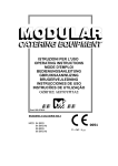
10.1
EXPLODED FUNCTIONAL PARTS TABLES
Mod. SG-GN 1/1
Mod. SGF-GN 1/1
Fig. 1
2
1
26
4
16
20
3
14 13
18
11
19
10
9
12 5
21 7
6
8
Fig. 1
Fig. 3
3
CHIUSO
FERME'
GESCHLOSSEM
CLOSED
DICHT
PILOTA
VEILLEUSE
ZÜNDFLAMME
PILOT
WAAKULAM
MAX
MAXIMUM
LAAG
MIN
MINIMUM
HOOG
28
24
27
25
17