1
Samsung Electronics
GB-4
D
I
G
I
T
A
L
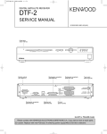
To connect any external Audio Hi-Fi system, the receiver has been provided
with two RCA connectors at the back of the receiver,
marked with AUDIO L and R respectively to connect the left and right Audio.
6. CONNECTING EXTERNAL AUDIO / HI-FI SYSTEM
To connect a VCR, the DSR9500 has been provided with SCART
at the rear marked "VCR".
Using a SCART connector, the VCR can be connected to the receiver.
5. CONNECTING YOUR VCR
S
To facilitate the user using analog receiver to view analog channels,
DSR9500 has been provided with a loop through terminal marked as "LOOP".
Connect the coaxial cable from this terminal to the IF input terminal of
your analog receiver. Now by keeping the DSR9500 in standby,
you will be able to tune and view analog channels from
your analog receiver.
4. CONNECTING YOUR ANALOG RECEIVER
To connect the receiver with your television, you can use three methods;
via Scart Cable, RF cable, or RCA cable.
Connect the RF cable to the terminal marked "TV" at the rear panel
of DSR9500 and its other end to the TV RF input socket.
In the case of connecting your TV through SCART cable, connect the
SCART connector marked TV to the respective SCART port on the TV.
3. CONNECTING THE RECEIVER TO TV
After installing your antenna system, connect the coaxial cable from the
LNB of your antenna to "LNB" terminal marked at the rear
of the DSR9500.
All cable connectors should be finger tightened; do not use any kind
of wrench while tightenning connectors. The cable should be 75ohm
impedance coaxial twisted at the end with an "F" type connector.
2. CONNECTING THE RECEIVER WITH DISH SYSTEM
Your DSR9500 should be placed under proper ventilation.
Don’t put in completely enclosed cabinet that will restrict the flow of air,
resulting in overheating.
The location should be safeguarded from direct sunlight,
excess moisture, rough handling or household pets.
Avoid stacking other electronic components on the top of the receiver.
The location should be safely accessible by the cable from your
antenna system.
1. LOCATION OF THE RECEIVER
CONNECTING YOUR "DSR9500"
A
T
E
L
L
I
T
E
R
E
C
E
ANT.IN
TV
I
R
L
V
AUDIO
E
VIDEO
R
TV
VCR
S-VHS
GB-5
S.PDIF
RS232 PORT
LOOP
LNB
950-2150MHz
500mA
POWER
WARNING! DO NOT OPEN
ELECTRICAL SHOCK HAZARD
Pmax 40W
AC95-240V 50/60Hz
Fuse:250V T2A
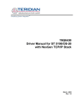
Note : The following Common Interface CAMs are available now:
IRDETO, CONAX, CRYPTOWORKS, VIACCESS, NAGRAVISION,
SECA, Etc.
Connecting Figure
●
Insert the smart card into the CAM gently with the gold colored chip upwards
Slide in the CAM gently inside the slot so that it sits in the socket tightly.
● Close the door.
● To remove the CAM push the button provided by the side of the CAM slot.
The CAM will be ejected from the socket.
●
The DSR 9500 supports Common Interface CAMs under DVB specification.
The CI CAMs include a built-in smart card reader.
(For models DSR 9500 CI, DSR 9500 VIA CI)
8. INSERTING COMMON INTERFACE CAM AND SMARTCARD
Note : Insert the Smartcard with the gold coloured chip facing downwards.
In order to view a scrambled service, you need to have the appropriate
conditional Access Module and a valid Smartcard. This DSR9500 has the
Viaccess CAS embedded to view Viaccess programmes.
7. INSERTING SMARTCARDS FOR VIACCESS SERVICES
CONNECTING YOUR "DSR9500"
2. Operating Instructions
2-1
2-2
I
G
I
T
Slot for Viaccess smartcard.
(For models DSR 9500 VIA, DSR 9500 VIA CI)
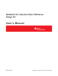
7. Card Slot
D
This is to receive the IR commands from the Remote
Control Unit.
6. Infrared Sensor
GB-6
Slot for Common Interface.
(For models DSR 9500 CI, DSR 9500 VIA CI)
5. CAM Slot
A
4. 7 Segment Display This LED display will show the current channel number.
While the receiver is in Standby mode, the display will
show the current time.
L
S
These keys are used to increase and decrease the volume level
manually.
These keys are used to change the channels.
7
,
6
,
5
3.
4
2.
3
This key is used to turn the receiver on and off (Standby).
2
1.
1
Front Panel
DESCRIPTION
A
T
E
L
L
I
T
7
6
SPDIF
S-VHS
5
4
RS232 PORT
3
LOOP
2
LNB
950-2150MHz
500mA
POWER
Pmax 40W
AC95-240V 50/60Hz
Fuse:250V T2A
1
WARNING! DO NOT OPEN
ELECTRICAL SHOCK HAZARD
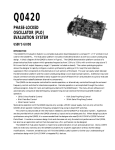
This is used to connect to your VCR.
E
12. TV
R
E
11. ANT.IN
C
E
I
V
E
R
GB-7
This is used to connect to your TV via RF cable.
This is used to connect your local RF channels to
your TV through Loop.
10. VIDEO, AUDIO R/L These RCA connectors are used to connect any external
video and audio.
This is used to connect to an external LNB switch.
This is used to connect to your TV.
8. VCR SCART
9. 0/12V
Output for connection to a digital amplifier.
7. TV SCART
This is used to connect STB to your TV by using S-VHS cable.
5. S-VHS
6. SPDIF
This is used to connect your receiver to a computer for reading
and loading data information.
To enable the connection of an Analog receiver,
The receiver is provided with this LOOP port.
4. RS 232 DATA PORT
3. LOOP
This port is to connect the coaxial cable from LNB of your dish.
The IF input is provided through this port and the input frequency
range is 950-2150 MHz. Also the voltage switching 13V and
18V is passed through this port.
TV
VCR
2. LNB
10 9 8
AUDIO VIDEO
This is to plug in the AC mains power cord.
The input AC voltage range is 95V to 240V, 50Hz/60Hz supply.
11
R
L
1. AC MAINS
12
ANT.IN
TV
Rear Panel
DESCRIPTION
Operating Instructions
Samsung Electronics
Samsung Electronics
)
4. TV/RADIO
3. Pg+/Pg-(
,
CH+
EXIT
LAST
EPG
FAV
MUTE
TV/RADIO
17
12
11
14
8
7
6
5
4
)
)
GB-8
D
I
G
I
T
A
L
This key is used to toggle between the TV channel and Radio
channel.
These keys are used to move up or down pages the menu.
S
A
T
These keys are to enter numeric values and to select the channel
directly by entering its number.
~
This is used to switch the receiver ON/STANDBY mode.
2. 0-9 Numerical keys (
1. POWER(
MENU
timer
POWER
Note : When inserting batteries, make sure that the polarity(+/-) is correct.
18
16
9
10
13
15
3
2
1
Remote Control Unit
DESCRIPTION
E
L
L
I
T
Electronic Program Guide button displays the TV/Radio Program
guide.
7. EPG
E
R
E
C
E
18. VOL+/VOL-(
17. CH+/CH-(
I
)
V
E
R
GB-9
) These keys are used to increase or decrease the volume.
These keys are used to move up or down pages
on the channel list.
These keys are used to change channels.
These keys are used to move the highlight bar for selecting
options on the menu, and this button is used to change channels
and increase or decrease the volume.
This key is used to enter and confirm any data to the receiver in the
menu system. This key is used to select the item. Press while viewing
TV and a list of channels is displayed.
15. OK(
)
This key is used to exit a menu or return to the previous menu.
14. EXIT
,
,
This key is used to open up the menu or return to the previous menu.
13. MENU
(
This key is used to display the programe information box in the screen.
This button functions same as the RED button on the menu. Press once
and you can get simple information on the program. Press twice and
you can get detailed information on the channel in text box.
12. INFORMATION
(RED) (
)
16.
This key is used to change the Audio to the left, right or both channels,
This button functions same as the BLUE button on the menu.
11. AUDIO(BLUE)
(
)
)
This key is used to select the soundtrack list for the current service.
This button functions same as the YELLOW button on the menu.
Press once and sound track appears.
Press twice and video track appears.
The sound and video track services are not provided for every
channel and depend on the conditions the operator is in.
This key is used to select the subtitle mode.
This button functions same as the GREEN button on the menu.
Press once and subtitle appears. You can select the language you
want using the channel +/- keys.
Press twice and Teletext with OSD appears.
Press three times and Teletext with VBI appears.
10. ALT(YELLOW)
(
)
9. TEXT(GREEN)
(
)
This key is used to call up directly whatever channel you were
watching list.
Use the key to switch between favorite lists.
6. FAV
8. LAST
This key is used to toggle between normal & muted audio.
5. MUTE
DESCRIPTION
Operating Instructions
2-3
2-4
Channel Number
Current Favorite
Channel Name
Press the Red (
) key twice while you are viewing a program.
G
I
T
A
L
S
A
T
E
L
L
I
T
GB-10
D
E
●
I
●
●
●
●
Press / keys to adjust the volume level.
● Press MUTE key to turn to silence mode.
● Press MUTE key again in order to cancel the mute function.
Select the channel by pressing
/
Press
key to watch that channel.
,
The icon
behind the channel name
symbolises scrambled channel, and
the
icon behind the channel name
symbolises lock channel.
/
Press
key to while you are viewing a program.
Select list by pressing TV/RADIO or FAV key.
.
R
Green
Yellow
Blue
Red
E
(
(
(
(
C
E
I
V
E
R
GB-11
) key - Favorites
) key - Alphabetical
) key - Provider
) key - Transponder
The colour key corresponds the following service list.
●
●
●
●
5. Service List
Press Yellow (
) key twice to see
the videotrack list.
● Press
/
and
key to select one.
●
4. Select Videotrack
To control the volume level :
2. Volume Control
Note : This service depends on service provider.
First you will see the banner described above.
After pressing the Red (
) key a second time you will receive detailed
program information.
●
Detailed program information
CAS Name
The number of soundtrack in current channel
Right Audio Status
Press the Red (
) key in view mode.
Select the channel by pressing Numerical (
~
) keys or
/
keys and select TV/RADIO key to move to TV or
Radio channel.
Program Information
Parental Lock
You will also see this picture each time you change channels.
When you press TV/RADIO key on the Remote Control Unit,
TV and Radio program are toggled.
●
●
Signal Status
Left Audio Status
●
Before you can view the television program, you must perform the installation.
Therefore you will see only menu images at first.
After the television channels have been programmed, you will see the following
picture(banner) each time you switch channels:
BASIC FUNCTION
Press Yellow (
) key to see
the soundtrack list.
● Press
/
and
key to select one.
3. Select Soundtrack
1. Display Screen
BASIC FUNCTIONS
Operating Instructions
Samsung Electronics
Samsung Electronics
GB-12
Press the Red (
) key on the remote control
unit to select the Transponder list.
● Use the
/
,
/
keys to select a
Transponder group that you want.
● Press the Red (
) key to toggle group and
channel list.
●
5.4 Service Transponder
Press the Blue (
) key on the remote control
unit to select the Provider list.
● Use the
/
,
/
keys to select a Provider
group that you want.
● Press the Blue (
) key to toggle group and
channel list.
●
5.3 Service Provider
Press the Yellow (
) key on the remote control
unit to select the Alphabetical list.
● Use the
/
,
/
keys to select a
Alphabetical group that you want.
● Press the Yellow (
) key to toggle group
and channel list.
●
5.2 Service Alphabetical
Press the Green (
) key on the control unit to
select the Favorites list.
● Use the
/
,
/
keys to select a favorite
group that you want.
● Press the Green (
) key to toggle group and
channel list.
●
5.1 Service Favorites
D
BASIC FUNCTIONS
I
G
I
T
A
L
S
A
T
E
L
L
I
T
Press EPG key while you are viewing a program.
Select the channel by pressing
key to watch this channel.
,
/
keys and press
E
R
E
C
E
I
V
E
R
GB-13
Press the Green (
) key to see the subtitle
language List.
● Use the
/
keys to select a subtitle
language you want.
● Press the
key and then the subtitle language you want is displayed
The menu display is carefully created and user friendly to assure the easy operation
of the receiver by the user. The main menu is classified into Six sub menus which
will carry out the various operations individually.
●
To change the subtitle language:
When the current broadcasting program provides
subtitle, press the Green (
) key to see
the current subtitle language list.
/
With the TV/RADIO or FAV key you can browse among the various programs lists.
) key - Use to display the program list until this day last week by
going back per one day.
Yellow (
) key - Use to display the program list until this day next week by
going forward per one day.
/ keys - Use to display the program list by 30minutes per block.
Green (
7. Subtitle
●
●
●
●
This function is displayed on the screen by using only time.
You will see "EPG" in the LED display of the receiver.
●
Note : 1. This service depends on service
provider.
2. After receiver recognized the GMT-time
from the signal which takes few seconds,
it can display correct EPG information.
EPG-Electronic Program Guide
The electronic program guide gives you a channel list
for the channels.
6. Program Information
BASIC FUNCTION
Operating Instructions
2-5
2-6
GB-14
Use the
/
keys to select a Teletext VBI
you want.
● Press the
key and then the Teletext VBI
you want is displayed on the screen.
●
To change the Teletext VBI:
When the current broadcasting program provides
Teletext VBI, press the Green (
) key three times
to see the current Teletext VBI list.
9. Teletext VBI
Use the
/
keys to select a Teletext OSD
you want.
● Press the
key and then the Teletext OSD
you want is displayed on the screen.
●
To change the Teletext OSD:
When the current broadcasting program provides
Teletext OSD, press the Green (
) key twice
to see the current Teletext OSD list.
8. Teletext OSD
BASIC FUNCTION
D
I
G
I
T
A
L
S
A
T
E
L
L
I
T
Plug in the AC main power and switch on the receiver.
Press MENU key to bring up the main menu.
The LED display will show "MENU".
You must follow the help message at the bottom
of the screen!
E
R
E
C
E
I
V
E
R
GB-15
If you have not entered your own PIN code
then the PIN code 0000 applies, which was
set at the factory.
Select "Installation" in the main menu mode to
select the sub menu.
● Enter the PIN code.
●
The menu provides settings for customizing, adding new services and displaying
the status of the receiver.
1. Installation
Before you begin with the "Installation"
menu, you should check in the 4th menu
"System Setup" whether all the information
there is applicable for you.
●
The sub menu topics will be displayed from 1 to 6.
For the sub-menus 1, 2 and 3 you need the PIN code.
The following on screen display will appear:
●
●
After installing your antenna system and DSR9500 with appropriate connectors.
Main Menu
OPERATING THE RECEIVER
Operating Instructions
Samsung Electronics
Samsung Electronics
GB-16
Select Satellite.
Select any transponder from above satellites and
check out the Frequency, Symbol Rate, FEC and
Polarity.
In case problems arise, ask your dealer.
●
●
D
I
G
I
T
A
If you have a DiSEqC 1.2 motorized system, then you can take advantage of
the DiSEqC 1.2 functions available.
1.2 Positioner Setting
L
22KHz: In case you are using a dual LNB or two antennas connected to a 22KHz
tone switch box, with the 22 KHz tone switch ("On", "Off" or "Auto") you
can switch between both LNB or antennas.
If you are using a Positioner, select this option. ( Yes or No )
●
Select LNB power supply "On".
Select the desired satellite name.
● Select the LNB type (frequency).
● Select the DiSEqC Mode
(Off, DiSEqC A, DiSEqC B, DiSEqC C, DiSEqC D, Tone Burst A, Tone Burst B)
●
S
A
T
E
L
L
I
T
Go to Stored Position.
E
●
R
E
C
E
I
V
E
R
GB-17
Select the Calculate Sat Positions to recalculate the satellite position and
When the stored position is reached then screen displays "Stop",
you can now continue with the further operations.
●
Note : The level indicated in the Signal Status is only for reference.
The signal quality may be adequate even though the level indicated is
not maximum.
Select Driving Mode:
You have an option to choose the positioner s
movement type: Continuous, Step or Time.
● Position the antenna with north, south, east
and west and use the / ,
/
key to drive
motor. key drives to west, key drives to east,
key drives to north and
key drives to south.
● If you finished driving of motor, select Store
current Position. and press
key, to reset
new driving motor.
●
key.
Complete control of the positioner s full functions
recommended for installers and professional users.
"Installer" mode :
1.2.1 User Mode
Enables control of basic positioner function
recommended for beginners. General user uses User mode.
"User" mode :
You can select the satellite and LNB setting conditions
to execute channel search and you can alter the settings
for 22KHz tone. The parameters set in this menu are
needed for programming the channels for the "Auto
scanning" and "Manual scanning".
The necessary information can be found at your antenna
and LNB brochures, or you can ask your dealer.
Select from Menu Mode:
●
OPERATING THE RECEIVER
1.1 LNB Setting
OPERATING THE RECEIVER
Operating Instructions
2-7
2-8
/
GB-18
To set the Value of Date and Time, use the
keys to change the value.
● Use the
/ keys to change position.
● Use the
/
keys to move each filed.
●
You can set the value according to your location.
D
I
G
I
T
A
L
This menu is only for the Solarsat antenna.
When you press this menu, you will get this message, This menu is only for the
Solarsat antenna. If you have one-press OK, otherwise-press EXIT.
1.3 Solarsat Setting
Select the Drive Motor West/East and use the /
keys to drive motor.
key drives to west and
key drives to east.
● Select Enable Limit , in order to enable Set Limit .
● Select Disable Limit , in order to disable Set Limit .
● Select Reset Positioner and
key to reset positioner.
S
A
T
E
L
L
I
T
Press
key.
Select the target satellite for manual search.
Load a transponder.
This option will enable the user to load any
transponder from the preprogrammed list
available within the receiver.
E
R
E
Input the
you want
● Input the
you want
●
C
E
I
V
E
R
GB-19
frequency of the transponder
to find.
symbol rate of the transponder
to find.
Note : When you enter Frequency after setting
Load TR to New, the entered information
must include at least one channel to make
channel save possible.
●
●
To tune-in new channels and weak signals, the DSR9500 has been provided with
the option "Manual Scanning" where the channel data can be entered by the user.
After selecting the "5. Manual Scanning" from the Installation Menu, the following
screen will be displayed:
1.5 Manual Scanning
All the channels in the list from the selected satellite will be
automatically downloaded.
After scanning you will see "Your digital receiver found..." .
Afterwards you return to Auto Scanning menu.
Auto Scanning menu will be displayed.
●
Off :
No Scan
All :
Scan all the channels
Only Free : Scan free channels
To download channels automatically:
You can select All/Off/Only Free option mode in
each satellite.
The sub menu Auto Scanning will enable download of off-air channels automatically
from the preprogrammed satellites.
After checking the positioner s state, installer should use
this menu. He should set the Disable Limits before
using User mode.
●
1.4 Auto Scanning
OPERATING THE RECEIVER
1.2.2 Installer Mode
OPERATING THE RECEIVER
Operating Instructions
Samsung Electronics
Samsung Electronics
GB-20
Note : This cause your previous settings to be deleted!
At the request window,
if you press
key, the receiver will be reset to factory
default settings automatically.
The screen display will be as follows:
This to restore the factory set values in case the user
has encountered some problems after changing any
values of channel data and others which may be in error.
1.7 Reset to Factory Defaults
2. When your searching type is set to Manual
during SMATV scanning, you must enter both
frequency and symbol rate.
Note : 1. When your searching type is set to Automatic
during SMATV scanning, you have only to enter
the alternative symbol rate(1~4) you want.
●
Select Searching Type Automatic or Manual .
Select Scan Mode All or Only Free .
● You can input alternative symbol rate from 1 to 4
●
In case that several generations use Antenna and LNB
in common, search the service the from 950 to 2150MHz.
D
I
G
I
T
A
L
Select the FEC(Forward Error Correction)of the transponder
you want to find.
You can select the value of 1/2, 2/3, 3/4, 5/6, 7/8 or Auto.
Select the polarization of the transponder you want to find.
(Horizontal/Vertical/Circular Left/Circular Right)
In the case of horizontal, 18V and in the case of vertical,
13V are output through LNB line.
Select Scan Mode All or Only Free .
Select Network Search Yes .
You can find more transponders using the home network.
Select PID searching Yes . You can manually search by entering individual
PID(Packet Identifier)(Video/Audio/PCR) values.
After select option, press
key to start the scan process.
1.6 SMATV Scanning
●
●
●
●
●
●
OPERATING THE RECEIVER
S
A
T
E
L
L
I
T
Enter the PIN code.
E
R
E
C
E
I
V
E
R
GB-21
Note : This feature doesn t delete transponder itself
but deletes the list of channels registered for
transponder.
Select the desired transponder list you want to
delete by pressing Red (
) key.
● Press
key for confirmation.
●
2.2 Delete Transponder
Note : This feature doesn t delete satellite itself
but deletes the list of channels registered
for satellite.
Select the desired satellite list you want to delete
by pressing Red (
) key.
● Press
key for confirmation.
●
2.1 Delete Satellite
If you have not entered your own PIN code PIN code
0000 applies, which was set at the factory.
●
The "Channel Organising" menu has seven
functions:
The "Channel Organising" menu is used to delete
the Satellites, Transponders and Channels or to make
Favorite channels or move channel as you want.
2. Channel Organising
OPERATING THE RECEIVER
Operating Instructions
2-9
2-10
●
●
●
●
GB-22
Press FAV key to select another favorite list.
Then press
key for confirmation.
Right List : Adds a channel to the left list by pressing
the Red (
) key.
Left List : Deletes a channel by pressing the Red (
Select the desired channel list with
/
keys.
When you press the TV/RADIO key, TV list and Radio
list are toggled.
You can change TV list or Radio list by TV/RADIO key
and change favorite list by FAV key. This enables you to
create the 9 favorite TV and Radio list.
2.6 Favorite Channel
At the request window, press
key to delete
scrambled channels and press MENU / EXIT to exit.
2.5 Delete Scrambled Channels
At the request window, press
key to delete
all channels and press MENU / EXIT to exit.
2.4 Delete All Channel
Select the desired channel you want to delete by
pressing Red (
) key.
● Press
key for confirmation.
●
2.3 Delete Channel
OPERATING THE RECEIVER
D
I
G
) key.
I
T
A
L
S
A
T
E
L
L
I
T
Select the desired list with / keys.
Select channel by pressing Red (
) key.
● Press
/
,
/
keys to change the position
of the channel you want, and press
key for
confirmation.
● Press Red (
) key again to return to previous
state
● If you want to return the channel to the initial
position, do not press
key but press
blue (
) key.
E
R
E
C
E
I
V
E
R
GB-23
To edit channel name, press Green (
) key.
Font Table will be displayed.
● Select desired character with
/ ,
/
, and
then press
key to paste character to the string.
● Press MENU key to save tge set data.
●
●
●
2.7 Move & Edit Channel
OPERATING THE RECEIVER
Operating Instructions
Samsung Electronics
Samsung Electronics
●
Press Red (
To cancel the lock :
GB-24
D
) key again in order to cancel the lock.
This will lock the channel. Whenever you need to view
the channel, you will have to enter the PIN at the request
window.
●
Select the channel by pressing
/
,
/, , / .
When you press the TV/RADIO key, TV list and Radio
list are toggled.
● Select the channel lock by pressing Red (
) key.
● Press
key for confirmation.
●
I
G
I
T
A
L
S
A
T
E
L
L
I
T
E
R
E
C
E
I
V
E
R
GB-25
If you forget the PIN Code, please refer to the following instruction;
1. Press MENU Key on the RCU
2. Select "System Setup"
3. Select "System Information"
4. Press "0000"
Note :
3.1 Set Channel Lock
Please remember the PIN code should be a 4 digit
numerical value.
THE FACTORY PRESET PIN CODE : 0 0 0 0.
Enter PIN code.
In this option, you need to enter the current PIN
code at the first cursor, and at the second cursor
enter the desired PIN code.
To confirm, you need to enter the new PIN code
again.
If you have not entered your own PIN code then the PIN code 0000 applies,
which was set at the factory.
●
On selecting this menu, you will have two options:
to set lock for any desired channel and to change
your PIN value.
To change the PIN code, select the second option "Change PIN Code".
This "Parental Lock" feature sets viewing restrictions
and prevents unauthorized access to your DSR9500
through the PIN (Personal Identification Number),
which is a 4 digit number.
(The factory preset PIN code : 0000)
This will take you to the following menu:
3.2. Change PIN Code
OPERATING THE RECEIVER
3. Parental Lock
OPERATING THE RECEIVER
Operating Instructions
2-11
2-12
GB-26
Select OSD Transparency type.
The OSD Transparency level from 0 to 100%.
● Set the display duration of the information(banner) box
displayed in the screen.
The time ranges from 0.5 to 60.0 seconds.
●
You can set the OSD transparency and the display time.
4.2 OSD Setting
To accommodate user from different regions
speaking different languages.
● To select the desired language menu,
press
/ keys to change language and press
.
● The OSD Language, Soundtrack, Teletext, Subtitle,
or EPG will vary according to the selected language.
●
The "Language Selection"option allows the user to
select the desired language of the OSD, Soundtrack,
Teletext, Subtitle or EPG.
4.1. Language Selection
D
I
G
I
T
A
L
S
A
T
E
L
L
I
T
E
●
R
E
C
E
I
V
E
R
GB-27
Place the cursor on this sub menu and press
.
Press the
/
, / keys to change the Local
time in Time Zone.
The local time will be changed according to your
location.
● Press the
/ keys to choose event repetition
you want to reserve :
Daily, Every Sunday, Every Monday, Every Tuesday,
Every Wednesday, Every Thursday, Every Friday,
Every Saturday, Once.
● Press the Numerical (
~
) keys to set the time you want
and press the / keys to choose a switch time
you want to reserve.
● Select TV program to set the event program by
pressing / keys.
When you press the TV/RADIO key, TV program and Radio program
are toggled.
●
4.4 Time & Timer Setting
●
●
●
●
●
Select the TV system : PAL, SECAM.
Select the TV type according to your TV:
STANDARD 4: 3 ratio or WIDE SCREEN
16 : 9 ratio type.
Select the aspect ratio conversion :
Letter box, Pan & Screen, Mixed or Full.
Select the Video Signal Type :
Composite+RGB or Composite.
Select the RF Channel.
Select Broadcasting System : B/G, I or D/K.
You can set the various media settings you want.
Place the cursor on this sub menu and press
.
This option enables you to change the factory preset
system settings as per your requirements.
●
4.3 Media Settings
OPERATING THE RECEIVER
4. System Setup
OPERATING THE RECEIVER
Operating Instructions
Samsung Electronics
Samsung Electronics
1.
2.
3.
4.
5.
6.
7.
GB-28
D
I
G
I
T
A
L
S
Plug on both master & slave receivers
Master Box(Installed Box) : Stand-by Mode
Slave Box(Installing Box) : Menu Mode
Connect 2 Boxes with RS232 serial cable (Both end should have male connector)
Select '4. System Setup'
Press '7' key on RCU
Press 'OK' to start channel data copy
If you want to copy the channel data from one receiver
to another, please follow the instruction below.
Please make your own channel data, such as favorite
& lock channel with your own master box.
Then take your master box when you install
another box.
4.7 Copy Channel Data
If there is a new version of software to download,
you are asked if you will update or not.
If you press
key, the update starts right away.
In case update is impossible, you get this message
"You can’t update software!" Or in case you don’t need to update,
"You don’t need to update software!" will be displayed.
During downloading don’t turn off the STB.
You can download and upgrade the software of this
STB through ASTRA, Sirius and Hotbird satellite when
the new software is released.
A
T
E
L
L
I
T
You can see the Common Interface CAM’s name
which has been inserted.
"Not installed" is displayed when there is no CAM in slot.
E
R
E
C
E
I
V
E
R
GB-29
5. Authorization:
This option would indicate the authorization status
of the Smartcard.
4. Issuer Information:
Here you can call up all information stored on
the Smartcard by the publisher.
3. Change Lock indicator:
You can change the lock status of the Viaccess Smartcard.
Note : This service is not offered by all channels.
2. Change Parental Rating:
Change the setting for the family filter,
if necessary.
1. Change PIN code:
Change the PIN code of the Smartcard,
if necessary.
6. Embedded Viacces
SLOT B:
SLOT A:
This STB is equipped with two PCMCIA slots,
which enable the use of two CI-CAMS.
When a Common Interface CAM is inserted inside
the PCMCIA slot,
the system detects the type of the CAM automatically
and display in the main menu.
On choosing this menu, you will be able to access
the different options available with the type of the
CAM like authorizations, pre-booking, package
details etc.,
If you have to contact your service provider or a service
center they might ask for information available from this
menu.
Place the cursor on this sub menu and press
key.
The following will be the on-screen display.
4.6 Software Upgrade
5. Common Interface
OPERATING THE RECEIVER
4.5 System Information
OPERATING THE RECEIVER
Operating Instructions
2-13
2-14
Power cord
not plugged in correctly
Receiver in Standby mode;
Scart not connected tightly
to video output of television;
incorrect channel or video
output selected on television
Audio cord connected
incorrectly;
Loudness level = 0;
Muting active
incorrect operation;
No display LED on
the front panel;
No power supply
No pictures on the screen
No sound
Remote Control does not
operate directly
Antenna cable not connected
or not tight;
LNB defective;
incorrect position of the
satellite antenna;
Satellite not yet set
Smartcard:
- not plugged in correctly;
- not plugged in.
On-Screen Error Message
"Searching for signal"
On-Screen Error Message
"Channel data
does not exist."
On-Screen Error Messages:
"Please check the
Smartcard";
"Please insert the
Smartcard".
(depend on model)
Check the Smartcard.
"Insert the Smartcard."
Scan of in "Automatic scanning"
or "Manual scanning" menu
Change LNB;
Check position and correct,
Check the signal strength in
the "Auto Scan" menu
Check connection and correct;
GB-30
D
I
G
I
T
A
L
S
Check the signal strength in
the "Auto Scan" menu, correct alignment
of your antenna
Point remote control
towards the Receiver.
Replace batteries or insert correctly
Increase loudness on television set;
Press the MUTE key
Check connection and correct;
Check channel and video output and
correct (TV instruction manual)
Set receiver to "On";
Check connection and correct;
Power cord plug in correctly
Solution of the problem
The device, packaging material (e.g. Styrofoam) and the batteries
must never be disposed of with household refuse.
Please obtain appropriate information about the regulations in your community,
and dispose of all refuse in accordance with regulations at the separate
locations provided.
DISPOSAL
Signal strength to low
Poor picture quality
Batteries dead or inserted
incorrectly
Possible cause
Problem
TROUBLESHOOTING
A
T
E
L
L
I
T
E
R
E
Outer FEC:
C
E
I
V
E
R
GB-31
950 ~ 2150 MHz
-65 ~ -25 dBm
479.5 MHz
PLL frequency synthesizer
75 Ω unbalanced
F type female
13 V/18 V, 22 KHz tone
1.2 supported
Tuner
Freq. Range:
Input signal level:
First IF freq.:
Channel selection:
Input impedance:
Connector type:
LNB power control:
DiSEqC:
QPSK DEMODULATION (DVB-S)
2 ~ 45 Ms/s
Viterbi Convolutional
Coding Rate - 1/2,2/3,3/4,5/6,7/8
Reed Solomon Coding (204,188) t = 8
SMPS
95 ~ 240V AC 50/60 Hz
250 V/T2 A
Power supply
Type:
Input voltage:
Fuse rating:
Demodulator
Type:
Symbol rate:
Inner FEC:
32, 44.1 and 48 KHz sampling
frequencies,
volume control and mute function through
Remote Control Unit.
modulator output,
compatible for both SCPC/MCPC,
supports aspect ratio 4:3 (normal) and
16:9 (wide screen)
supporting DiSEqC 1.2 version,
13 V/18 V switching,
22 KHz continuous tone control
7 segment LED display,
auto and manual scan facility,
channel organizing (programmable),
SCARTS & RCA output,
low power consumption
4. Audio section
MPEG 1 audio layer I & II
mono, dual, stereo and joint stereo audio
mode,
3. Video section
DVB-S compliant,
MPEG-2 video (MP@ML)
2 - 45 Ms/s symbol rate
2. Tuner section
950 ~ 2150 MHz wide band tuner,
IF output with DC pass loop for analog
receiver,
1. User section
4000 programmable channels,
software download via satellite & PC,
advanced Electronic Program Guide,
multi-language supported for OSD,
DiSEqC 1.2 supported full function
infrared remote control unit,
TECHNICAL SPECIFICATIONS
Operating Instructions
Samsung Electronics
Samsung Electronics
D
I
G
I
T
A
CH 21_69 (preset to CH 21)
PAL B/G, K, I
70±5 dBµV
IEC male
IEC female
PLL frequency synthesizer
RF modulator
Modulator output:
Video type:
UHF output level:
Output connector:
Ant. O/P connector:
Tuning method:
GB-32
YC p_p 1Volt (±10%)
L
VIDEO (CVBS, RGB), AUDIO R&L
VIDEO (CVBS), AUDIO R&L
VIDEO (CVBS), AUDIO R&L
S
A
MPEG 1 ISO/TEC 11172~3 layer I & II
mono, dual, stereo, joint stereo
32,44.1,48 KHz
MPEG 2 ISO/TEC 13818
(transport stream)
MPEG 2 MP@ML (4:2:2)
1~ 15 Mb/s
4:3 (normal) & 16:9 (widescreen)
720(H) x 576(V) x 50 fields/sec
A/V output
TV SCART:
VCR SCART:
RCA JACK:
SPDIF Digital Audio Output
S-VHS
Audio Decoder
System decoding:
Audio mode:
Sampling frequency:
Profile and level:
Data rate:
Video formats:
Picture resolution:
Video decoder
System decoding:
TECHNICAL SPECIFICATIONS
T
E
L
L
I
T
interface & descramble
RS232C, Max. 115.2 kB
9 pin D-type female
E
R
E
C
E
I
V
E
R
GB-33
Common Interface
(For models DSR 9500 CI, DSR 9500 VIA CI)
Module Type:
PCMCIA TYPE II x 2
Available CAM:
VIACCESS, IRDETO, NAGRAVISION,
CRYPTOWORKS, CONAX, SECA, Etc.
Smart card
2 slots, embedded Viaccess:
Embedded descrambler
VIACCESS conditional access system.
Serial data interface
Standard:
Connector type:
Operating Instructions
2-15
Operating Instructions
MEMO
2-16
Samsung Electronics
3. Software Upgrade and Installation
3-1 Flash Memory Writing process
How to input software after changing Boot software and replacing Flash Memory.
3-1-1 JPI Setting Manual
1) JPI exe Program : Setting ver R1.80
Make C:\STM\ST20R1.80 folder in C and copy exe file.
Execute setup file in C:\STM\ST20R1.80 folder.
2) PC Setting
Execute vppi set in bin folder, opening C:\STM\ST20R1.80\bin folder
Port type in vppi set up : Auto Detect -> EPP
Access Mode : after altering Synchronous -> Interrupt,
Click Apply and close “vppi set up”.
Open Regedit exe in Windows (O) : regedit
HKEY_LOCAL_MACHINE double click -> SYSTEM double click -> CURRENT CONTROL SET double
click -> SERVICES double click -> VxD double click
vppi set click -> *Access Mode : 0x00000002(2)
*Port Type
: 0x00000003(3)
Ů Following line should be added at Autoexec.bat of PC.
SET ST20ROOT=C:\STM\ST20R1.80
SET STVM_HOME=C:\STM\ST20R1.80
SET TOOLSET=C:\STM\ST20R1.80
3) Caution
Ů When Defaulting in vppi set up (in case of not altering)
Access Mode : 0x00000003(3)
Ů Port Type
: 0x00000000(0)
Ů When inputting boot program as JPI, following items should be
omitted in C:\windows\system.ini file[386Enh].
device=C:\ST20SWC\tools\vwrun.386
device=C:\ST20SWC\tools\vb045st.386
device=C:\ST20SWC\tools\vb008st.386
* If copied by PPI, above items should be included.
Samsung Electronics
3-1
Software Upgrade and Installation
3-1-2 Boot Software Input Process (Same Process in Main Software Installing)
<How to install software using JPI Adapter>
LPT 1
JPI adapter
PC
DC 9V
2 20V
AC
S
JPI Port
M
P
Main
S
DSR
PCB
9 500
Fig. 3-1
ΠPrepare PC and JPI, DSR 9500 as above figure.
´ Connect MAIN BOARD to JIG, JPI ADAPETER to JPI Port of MAIN PCB.
Then JP102(Jumper) Short of Main Board.
ˇ Approve a power source of POWER SUPPLY in the product set.
¨ Convert PC into MS-DOS MODE.
ˆ Execute C:\amd-boot\flash file name (SETTING UP ST20 DCU TOOLSET 1.6.2 SETTING END)
Ø After the power source of POWER SUPPLY OFF.
Then disassemble from JPI ADAPTER CONNECTER.
Ů SRF00901EA (FTA)
Ů SRF02901EA (CI)
Ů SRV20901EA (EM VIA)
Ů SRV22901EA (VIA CI)
-> C:\amd-boot\flash boot_FTA_9500_1
-> C:\amd-boot\flash boot_CI_9500_1
-> C:\amd-boot\flash boot_VIACCESS_9500_1
-> C:\amd-boot\flash boot_CI_VIACCESS_9500_1
“Message Check”
Program Start
Erased Block 65 OK!
Erased Block 66 OK!
Erased Block 67 OK!
Erased Block 68 OK!
Erased Block 69 OK!
received 65 block
entering fast mode programming sequence from C05e0000 to 7ffe0000
received 66 block
entering fast mode programming sequence from C05f0000 to 7fff0000
received 67 block
entering fast mode programming sequence from C05f8000 to 7fff8000
received 68 block
entering fast mode programming sequence from C05fa000 to 7fffa000
received 69 block
entering fast mode programming sequence from C05c0000 to 7fffc000
romtool : Operation Complete
Test Mode
3-2
Samsung Electronics
Software Upgrade and Installation
3-1-3 MAIN Software Install Process
COM 1
PC
RS-232
2 2 0 V
A C
S
M
P
Main
S
D S R
PCB
9 5 0 0
Fig. 3-2
ΠOpen DSR.TRM file while executing HYPERTERMINAL of PC.
Port
: Select to COM 1 port currently used.
Baudrate : 115200
´ As Vol-up key of Front PCB presses, POWER(PLUG) ON.
Ů SRF00901EA : Samsung Brand FTA Model
Loader version x. x
Ů SRF02901EA : Samsung Brand CI Model
Loader version x. x
Ů SRV20901EA : Samsung Brand EM VIACCESS Model
Loader version x. x
Ů SRV22901EA : Samsung Brand CI+VIACCESS Model
Loader version x. x
ˇ Send a file at Download ROM image. ( PROTOCOL : 1K XMODEM )
¨ Select Main Program (C:\main\DSR9500_2002_04_03_120_44D2.bin) by each kinds as selecting the File Send of
Transfer or Hyperterminal.
ˆ Check if the normal message appears.
Samsung Electronics
3-3
Software Upgrade and Installation
MEMO
3-4
Samsung Electronics
1. Precautions
1. Be sure that all of the built-in protective devices are
replaced. Restore any missing protective shields.
2. When reinstalling the chassis and its assemblies, be
sure to restore all protective devices, including :
control knobs and compartment covers.
3. Make sure that there are no cabinet openings
through which people--particularly children
--might insert fingers and contact dangerous
voltages. Such openings include the spacing
between the picture tube and the cabinet mask,
excessively wide cabinet ventilation slots, and
improperly fitted back covers.
(READING SHOULD
NOT BE ABOVE
0.5mA)
LEAKAGE
CURRENT
TESTER
DEVICE
UNDER
TEST
TEST ALL
EXPOSED METER
SURFACES
2-WIRE CORD
ALSO TEST WITH
PLUG REVERSED
(USING AC ADAPTER
PLUG AS REQUIRED)
EARTH
GROUND
Fig. 1-1 AC Leakage Test
If the measured resistance is less than 1.0 megohm
or greater than 5.2 megohms, an abnormality exists
that must be corrected before the unit is returned
to the customer.
4. Leakage Current Hot Check (See Fig. 1-1) :
Warning : Do not use an isolation transformer
during this test. Use a leakage current tester or a
metering system that complies with American
National Standards Institute (ANSI C101.1,
Leakage Current for Appliances), and Underwriters
Laboratories (UL Publication UL1410, 59.7).
5. With the unit completely reassembled, plug the AC
line cord directly the power outlet. With the unit’s
AC switch first in the ON position and then OFF,
measure the current between a known earth
ground (metal water pipe, conduit, etc.) and all
exposed metal parts, including : antennas, handle
brackets, metal cabinets, screwheads and control
shafts. The current measured should not exceed
0.5 milliamp. Reverse the power-plug prongs in the
AC outlet and repeat the test.
6. X-ray Limits :
The picture tube is designed to prohibit X-ray
emissions. To ensure continued X-ray protection,
replace the picture tube only with one that is the
same type as the original.
Samsung Electronics
7. Antenna Cold Check :
With the unit’s AC plug disconnected from the
AC source, connect an electrical jumper across the
two AC prongs. Connect one lead of the ohmmeter
to an AC prong.
Connect the other lead to the coaxial connector.
8. High Voltage Limit :
High voltage must be measured each time
servicing is done on the B+, horizontal deflection
or high voltage circuits.
Heed the high voltage limits. These include the
X-ray protection Specifications Label, and the
Product Safety and X-ray Warning Note on the
service data schematic.
9. Some semiconductor (“solid state”) devices are
easily damaged by static electricity.
Such components are called Electrostatically
Sensitive Devices (ESDs); examples include
integrated circuits and some field-effect transistors.
The following techniques will reduce the
occurrence of component damage caused by static
electricity.
10. Immediately before handling any semiconductor
components or assemblies, drain the electrostatic
charge from your body by touching a known
earth ground. Alternatively, wear a discharging
Wrist-strap device. (Be sure to remove it prior to
applying power--this is an electric shock
precaution.)
1-1
Precautions
11. High voltage is maintained within specified limits
by close-tolerance, safety-related components and
adjustments. If the high voltage exceeds the
specified limits, check each of the special
components.
12. Design Alteration Warning :
Never alter or add to the mechanical or electrical
design of this unit. Example : Do not add
auxiliary audio or video connectors.
Such alterations might create a safety hazard.
Also, any design changes or additions will void
the manufacturer’s warranty.
13. Hot Chassis Warning :
Some TV receiver chassis are electrically
connected directly to one conductor of the AC
power cord. If an isolation transformer is not
used, these units may be safely serviced only if
the AC power plug is inserted so that the chassis
is connected to the ground side of the AC source.
To confirm that the AC power plug is inserted
correctly, do the following : Using an AC
voltmeter, measure the voltage between the
chassis and a known earth ground. If the reading
is greater than 1.0V, remove the AC power plug,
reverse its polarity and reinsert. Re-measure the
voltage between the chassis and ground.
14. Some TV chassis are designed to operate with 85
volts AC between chassis and ground, regardless
of the AC plug polarity. These units can be safely
serviced only if an isolation transformer inserted
between the receiver and the power source.
18. Picture Tube Implosion Warning :
The picture tube in this receiver employs
“integral implosion” protection. To ensure
continued implosion protection, make sure that
the replacement picture tube is the same as the
original.
19. Do not remove, install or handle the picture tube
without first putting on shatterproof goggles
equipped with side shields. Never handle the
picture tube by its neck. Some “in-line” picture
tubes are equipped with a permanently attached
deflection yoke; do not try to remove such
“permanently attached” yokes from the picture
tube.
20. Product Safety Notice :
Some electrical and mechanical parts have special
safety-related characteristics which might not be
obvious from visual inspection. These safety
features and the protection they give might be
lost if the replacement component differs from the
original--even if the replacement is rated for
higher voltage, wattage, etc.
Components that are critical for safety are
indicated in the circuit diagram by shading,
(
or
).
Use replacement components that have the same
ratings, especially for flame resistance and
dielectric strength specifications. A replacement
part that does not have the same safety
characteristics as the original might create shock,
fire or other hazards.
15. Never defeat any of the B+ voltage interlocks.
Do not apply AC power to the unit (or any of its
assemblies) unless all solid-state heat sinks are
correctly installed.
16. Always connect a test instrument’s ground lead to
the instrument chassis ground before connecting
the positive lead; always remove the instrument’s
ground lead last.
17. Observe the original lead dress, especially near
the following areas : Antenna wiring, sharp
edges, and especially the AC and high voltage
power supplies. Always inspect for pinched, outof-place, or frayed wiring. Do not change the
spacing between components and the printed
circuit board. Check the AC power cord for
damage. Make sure that leads and components
do not touch thermally hot parts.
1-2
Samsung Electronics
8-4
8-2 Front - - - - - - - - - - - - - - - - - - - - - - - - - - - - - - - - - - - - - - - - - - - - - - - - -
8-6
8-7
8-8
8-9
8-10
8-11
8-12
8-13
8-14
8-15
8-16
8-17
8-19
8-20
8-21
8-18
8-4 Reset - - - - - - - - - - - - - - - - - - - - - - - - - - - - - - - - - - - - - - - - - - - - - - - -
8-5 CIMAX (Only for CI, VIA CI Models) - - - - - - - - - - - - - - - - - - - - - - - - - - -
8-6 NVM - - - - - - - - - - - - - - - - - - - - - - - - - - - - - - - - - - - - - - - - - - - - - - - - -
8-7 DCU - - - - - - - - - - - - - - - - - - - - - - - - - - - - - - - - - - - - - - - - - - - - - - - - -
8-8 Sub-Bank - - - - - - - - - - - - - - - - - - - - - - - - - - - - - - - - - - - - - - - - - - - - -
8-9 Audio - - - - - - - - - - - - - - - - - - - - - - - - - - - - - - - - - - - - - - - - - - - - - - - -
8-10 Video RAM - - - - - - - - - - - - - - - - - - - - - - - - - - - - - - - - - - - - - - - - - - - -
8-11 RS232 - - - - - - - - - - - - - - - - - - - - - - - - - - - - - - - - - - - - - - - - - - - - - - - -
8-12 Output - - - - - - - - - - - - - - - - - - - - - - - - - - - - - - - - - - - - - - - - - - - - - - -
8-13 Smart Card #0 (Only for EM VIA, VIA CI Models) - - - - - - - - - - - - - - - - - - -
8-14 Smart Card #1 (Only for EM VIA, VIA CI Models) - - - - - - - - - - - - - - - - - - -
8-15 Channel - - - - - - - - - - - - - - - - - - - - - - - - - - - - - - - - - - - - - - - - - - - - - -
8-16 Front Connection - - - - - - - - - - - - - - - - - - - - - - - - - - - - - - - - - - - - - - - -
8-17 Main CPU - - - - - - - - - - - - - - - - - - - - - - - - - - - - - - - - - - - - - - - - - - - - -
8-18 Flash Memory - - - - - - - - - - - - - - - - - - - - - - - - - - - - - - - - - - - - - - - - - -
8-19 Modem Interface (Option) - - - - - - - - - - - - - - - - - - - - - - - - - - - - - - - - - -
Samsung Electronics
8-5
8-3 Power - - - - - - - - - - - - - - - - - - - - - - - - - - - - - - - - - - - - - - - - - - - - - - - -
Main PCB
8-2
8-1 S.M.P.S. - - - - - - - - - - - - - - - - - - - - - - - - - - - - - - - - - - - - - - - - - - - - - - -
8. Schematic Diagrams
8-1
8-2
C2
-
D3
D4
102pF (NK)
C4
+
C1
YFW800-02
CON1
DRAIN
+
ATS3550L
BD1
D5
1N4937
D6
10
R4
101pF/1KV
C24
47K
R1
KME 33uF/50V
C7
1N4937
103pF/1KV
C6
!
THIS SYMBOL MAY ALSO BE PUT ADJACENT
O THE
T RELEVANT COMPONENT.
THIS SYMBOL SHALL NOT BE PLACED
NO
COMPONENTS.
COMPLIANCE IS CHECKED
BY INSPECTION.
!
250V T2AL( ł…œ )
F1
C28
!
C8
223pF
GND
NK102
CAUTION
!
OPT1
KPC317
Vcc
100K
RP2
1L0380RB
Q1
IL0380RB
IN
KMG 82uF/400V
C3
MTZ-30B 1/2W
ZD1
CC104
C30
+
100K
R2
!
10D471
TNR1
!
9700
0.1uF/275V
L1
0.1uF/275V
102pF (NK)
D2
D1
TH1
NTC10D9
!
!
!
!
!
C5
1N4007
T1
T-122
C9
LXV 1000uF/16V
YG811SO4R
D7
YG811-S04R
D8
LXZ 330uF/25V
SF20-04
D10
SF20-04
D9
SF20-04
D14
SF20-04
D11
1N4937
D12
+
+
+
+
+
+
+
22uH
L3
KIA431A
IC1
12uH
LXV 1000uF/16V
C11
C15
22uH
L6
LXZ 220uF/35V
C13
L5
LXZ 330uF/25V
C23
22uH
L4
LXV 220uF/50V
C17
22uH
L7
KME33uF/50V
C19
BD2
ATS3550L
KMG 330uF/25V
KMG 220uF/35V
KMG 330uF/25V
C16
+
12uH
L2
C12
C14
+
+
C29
OPT 1/2
C21
1.0K
R8
KIA431A
IC3
D
Q3
10K
R14
1
VIN
IC2
SHL 1uF/50V
S
1.0KF
R7
R6
1.07KF
VOUT
KA7812
2.2K 2W
R16
10K 1/2W
R15
FQP20N60/ IRFZ24A
KMG/KME 220uF/50V
C18
KME 33uF/50V
C20
+
+
+
KPC317
820
R5
KMG 330uF/25V
8-1 S.M.P.S.
G
Schematic Diagrams
+
GND
2
+
KMG 330uF/25V
C10
3.0K
R11
1.1K
R12
3
CTL
+17V
+23V
GND
+30V
+7.5V
+12V
GND
+5V
+3.3V
GND
+5V
GND
BLACK
Samsung Electronics
OUTPUT
13
12
11
10
9
8
7
6
5
4
3
2
1
CON2
Q10
2222
5VD
Q12
2222
8
9
12
12
Samsung Electronics
Q11
2222
Q13
2222
6
U11
TOF3464BG
8-2 Front
11
7
4
2
1
10
5
3
1K
1K
R13
R14
R15
R16
R17
R18
R19
R20
R21
R22
1K
R12
11
7
4
2
1
10
5
3
1K
10K
R10
R11
5VD
100
100
100
100
100
100
100
100
SW12
RIGHT
D12
1N4148
SW11
DOWN
D11
1N4148
SW10
UP
D10
1N4148
9
15
1
2
3
4
5
6
7
74HC595
QH^
G
13
12
10
11
14
74HC595
QH^
G
QA
SER
QB
QC SRCLK
QD
QE SRCLR
QF
QG
QH
RCLK
U10
D14
1N4148
13
12
10
11
14
5VD
D
SW14
POWER
QA
SER
QB
QC SRCLK
QD
QE SRCLR
QF
QG
QH
RCLK
U12
9
15
1
2
3
4
5
6
7
D13
1N4148
SW13
LEFT
D
D
5VD
D
5VD
D
5VD
C12
104
C11
104
CP1
47/16
10K
R10
C10
104
2
T10
TSOP1238UU1
KEY-IN
PWR_LED
RCU_D
5VD
CHA
PWR1
D
+
KEY-IN
D
3
6
8
9
1
D
CON10
1
2
3
4
5
6
7
8
9
10
J10
RCU_D
8-3
Schematic Diagrams
NC
C70
NC
C75
104
U73
NC
GND
OUT
VI
+
5VD
+
5VD
U70
LM1117]
R70 NC
1
2
3
CP75
470u/16V
CP71
1
2
3
4
5
6
7
8
9
10
11
12
13
CON13
J70
BC3560
BC3560
BC3560
BC3560
BD72
BD73
BD74
BD75
3V3
BC3560
BD71
N.C
R2011
+ CP76
NC
3V3
+ CP72
220u/16
N.C
R2010
LOW_P
BC3560
BD70
5VD
3.3V
12V 8V
VIDEO_PWR
470/16
CP70
5VD1
BT
5VD1
24V 17V
104
C71
3.3V
1
LM1117
U71
R2012
0
IN
OUT
GND
8-4
8-3 Power
Schematic Diagrams
GND
OUT
VI
2
220u/16V
CP73
3.3V_CH
3V3
104
C72
8V
C73
104
7805
U72
OUT
GND
IN
3
2
1
3
2
1
1
2
3
CP74
100u/16V
104
C74
Samsung Electronics
5VA
U102
DS1813-15
GND
1
JR100
TSW
RST
C126
1nF
2
Samsung Electronics
8-4 Reset
3
VCC
TP136
R178
33
/RST
TP129
R177
1K(2012)
5VD
/MCU_RESET
1
2
3
4
5
6
7
I1
O1
I2
O2
I3
O3
GND
VCC
I6
O6
I5
O5
I4
O4
U103
74HC14
FLASH_RST
14
13
12
11
10
9
8
5VD
104
C127
TP130
TP131
TP132
TP133
TP134
TP135
8-5
Schematic Diagrams
CI Asic R501
CI Max R502,
R503
Mounting
/CI_CS
/MEMRD
/MEMBE0
CI_CPU_Wait
TP530
TP531
TP532
TP533
R542
R524
R521
10K
NC
0
104
104
R549
R532
104
C504
104
C508
R533
0
MOCLKB
ª¨
18p
C529
C533
MOCLKA
MICLKB
MDOB7*
18p
C527
C534
C530
C528
C525
MDOA7*
C523
MICLKA
C521
MDOB6*
18p
C524
MDOB5*
18p
C522
MDOB4*
18p
C520
MDOA5*
C519
MDOA6*
C517
MDOA4*
C515
18p
C518
MDOB3*
18p
C516
MDOB2*
18p
C514
MDOA2*
MDOB1*
CI_Vcc_En0
C513
10
11
70
RSTB
CD1B#
CD2B#
CE1B#
CE2B#
RDY/IRQB#
WAITB#
119
71
6
81
85
100
121
MDOB0*
NC
NC
VCCEN
RSTB
CD1B#
CD2B#
CE1B#
CE2B#
RDY/IRQB#
WAITB#
MDOA1*
Cimax
VCC_ARRAY
VCC_PROC
VCC_TSI
VCC_TSO
VCC_DVB2
VCC_DVB1
GND_DVB1
GND_PROC
GND_ARRAY
GND_TSI
GND_TSO
GND_DVB2
DATOE
DATDIR
ADOE
ADLE
MDOA3*
36
38
51
64
65
109
8
9
37
39
52
86
MOCLKB
MOSTRTB
MOVALB
MDOB7*
MDOB6*
MDOB5*
MDOB4*
MDOB3*
MDOB2*
MDOB1*
MDOB0*
MICLKB
MISTRTB
MIVALB
MOCLKA
MOSTRTA
MOVALA
MDOA7*
MDOA6*
MDOA5*
MDOA4*
MDOA3*
MDOA2*
MDOA1*
MDOA0*
117
126
124
83
79
77
75
73
4
2
128
18p
(1608)
104
C507
5VD1
3V3
MOCLKB
MOSTRTB
MOVALB
MDOB7
MDOB6
MDOB5
MDOB4
MDOB3
MDOB2
MDOB1
MDOB0
108
91
104
115
113
111
106
102
98
95
93
123
88
97
89
90
C512
+
NC
0
0
EXTCS
EXTINT
CS
RD/DIR
WR/STR
WAIT/ACK
INT
MICLKB
MISTRTB
MIVALB
MDIB7
MDIB6
MDIB5
MDIB4
MDIB3
MDIB2
MDIB1
MDIB0
REG#
OE#
WE#
IORD#
IOWR#
RSTA
CD1A#
CD2A#
CE1A#
CE2A#
RDY/IRQA#
WAITA#
120
72
7
82
87
101
122
MDOA0*
100/16
CP501
C506
C505
104
C500
R550
69
68
67
66
13
12
18
17
16
15
14
A25
A24
A23
A22
A21
A20
A19
A18
A17
A16
A15
SA1
SA0
SCL
SDA
RST
CLK
MOCLK
MOSTRT
MOVAL
MDO7
MDO6
MDO5
MDO4
MDO3
MDO2
MDO1
MDO0
118
127
125
84
80
78
76
74
5
3
1
1
2
3
4
1
2
3
4
1
2
3
4
1
2
3
4
ª¨
ª¨
18p
18p
18p
18p
18p
18p
18p
18p
R506
R507
R508
1
2
3
4
1
2
3
4
MDIA7
MDIA6
RP503
33ARRAY MDIA5
MDIA4
MDIA3
MDIA2
RP515
33ARRAY MDIA1
MDIA0
R546
0
5VD1
R523
100
R526
100
R528
100
8
MDOB7
7 RP511 MDOB6
6 33ARRAYMDOB5
5
MDOB4
8
MDOB3
7 RP518 MDOB2
6 33ARRAYMDOB1
5
MDOB0
R514
100
R515
100
R516
100
8
MDIB7
7 RP508 MDIB6
6 33ARRAYMDIB5
5
MDIB4
8
MDIB3
7 RP517 MDIB2
6 33ARRAYMDIB1
5
MDIB0
MDOB0
MDOB1
MDOB2
MDOB3
MDOB4
MDOB5
MDOB6
MDOB7
MDIB0
MDIB1
MDIB2
MDIB3
MDIB4
MDIB5
MDIB6
MDIB7
R547
NC(2012)
C526
104
3.3VD
Q500
KST2222AL(NC)
R545
NC(2012)
REG#
OE#
WE#
IORD#
IOWR#
RSTA
CD1A#
CD2A#
CE1A#
CE2A#
RDY/IRQA#
WAITA#
100
100
100
8
MDOA7
7 RP504
MDOA6
6 33ARRAY MDOA5
5
MDOA4
8
MDOA3
7 RP516
MDOA2
6 33ARRAY MDOA1
5
MDOA0
100
100
100
8
7
6
5
8
7
6
5
TP521
TP520 TP527
TP519 TP526
TP525
3.3VD
TP529
33
33
33
33
33
29
28
27
26
25
24
23
22
21
20
19
33
32
31
30
34
35
63
62
61
60
59
RP505 58
33ARRAY 57
56
RP514 55
33ARRAY 54
53
MOCLKA
MOSTRTA
MOVALA
MDOA7
MDOA6
MDOA5
MDOA4
MDOA3
MDOA2
MDOA1
MDOA0
MICLKA
MISTRTA
MIVALA
MDIA7
MDIA6
MDIA5
MDIA4
MDIA3
MDIA2
MDIA1
MDIA0
R501
R502
R503
1
2
3
4
1
2
3
4
5VD1
CI_Vcc_En1
MDOA0
MDOA1
MDOA2
MDOA3
MDOA4
MDOA5
MDOA6
MDOA7
MDIA0
MDIA1
MDIA2
MDIA3
MDIA4
MDIA5
MDIA6
MDIA7
MICLK
MIVAL
MISTRT
MDI0
MDI1
MDI2
MDI3
MDI4
MDI5
MDI6
MDI7
IOIS16
GND
GND
GND
GND
CON501B
REG
CE1
CE2
OE
WE/PGM
IORD
IOWR
INPACK
IREQ
MOCLK
MOVAL
MOSTRT
MDO0
MDO1
MDO2
MDO3
MDO4
MDO5
MDO6
MDO7
C509
104
5VD1
101
136
103
102
69
129
75
110
77
83
112
113
128
84
8
7
6
5
4
3
2
1
VCC
VCC
RESET
VPP1
VPP2
RFRSH
WAIT
CD1
CD2
LTC1478
BVout
BVin2
BVin3
GND
AEN
AVins
AVin1
BVout
BVin1
BVins
BEN
GND
AVin3
AVin2
AVout
10K(2012)
U504
D0
D1
D2
D3
D4
D5
D6
D7
A0
A1
A2
A3
A4
A5
A6
A7
A8
A9
A10
A11
A12
A13
A14
10K(2012)
R520
R537
10K
VCC
VCC
RESET
VPP1
VPP2
RFRSH
WAIT
CD1
CD2
R536
10K
R519
AVout
PCMCIA SOCKET
IOIS16
GND
GND
GND
GND
REG
CE1
CE2
OE
WE/PGM
IORD
IOWR
INPACK
IREQ
125
MOCLK
130
MOVAL
131
MOSTRT
132
MDO0
133
MDO1
134
MDO2
105
MDO3
106SOCKET
PCMCIA
MDO4
107
MDO5
108
MDO6
109
MDO7
88
87
114
115
116
117
118
121
122
123
124
33
68
35
34
1
61
7
42
9
15
44
45
60
16
TP512
TP513
TP514
TP515
TP516
57
62
63
64
65
66
37
38
39
40
41
TP506
TP507
TP508
A0
A1
A2
A3
A4
A5
A6
A7
A8
A9
A10
A11
A12
A13
A14
D0
D1
D2
D3
D4
D5
D6
D7
5VD1
9
10
11
12
13
14
15
16
119
85
126
86
120
111
127
104
135
97
96
95
94
93
92
91
90
80
79
76
78
89
81
82
98
99
100
70
71
72
73
74
51
17
58
18
52
43
59
5VD1
R541
1K
R539
1k
C531
104
C510
104
R534
R535
MA0
MA1
MA2
MA3
MA4
MA5
MA6
MA7
MA8
MA9
MA10
MA11
MA12
MA13
MA14
MD0
MD1
MD2
MD3
MD4
MD5
MD6
MD7
MA0
MA1
MA2
MA3
MA4
MA5
MA6
MA7
MA8
MA9
MA10
MA11
MA12
MA13
MA14
29
28
27
26
25
24
23
22
12
11
8
10
21
13
14
36
67
MD0
MD1
MD2
MD3
MD4
MD5
MD6
MD7
30
31
32
2
3
4
5
6
C532
104
MA8
MA9
MA10
MA11
MA12
MA13
MA14
5VD1
+
CP503
100/16
+
CP502
100/16
10K(2012)
10K(2012)
C511
104
MA0
MA1
MA2
MA3
MA4
MA5
MA6
MA7
R517
R518
MD0
MD1
MD2
MD3
MD4
MD5
MD6
MD7
R540
0( ª¨ )
R538
0( ª¨ )
10K(2012)
10K(2012)
5VD1
1
2
3
4
1
2
3
4
1
2
3
4
1
2
3
4
1
2
3
4
1
2
3
4
SLOT2_VPP
SLOT2_VCC
SLOT1_VPP
SLOT1_VCC
SLOT2_VCC
SLOT2_VPP
C503
104
RP521
33ARRAY
RP509
33ARRAY
C502
104
3.3VD
RP520
33ARRAY
RP506
33ARRAY
RP519
33ARRAY
RP501
33ARRAY
3.3VD
8
7
6
5
8
7
6
5
SLOT1_VCC
SLOT1_VPP
8
7
6
5
8
7
6
5
8
7
6
5
8
7
6
5
G
DIR
A1
A2
A3
A4
A5
A6
A7
A8
U501
Q0
Q1
Q2
Q3
Q4
Q5
Q6
Q7
VCC
U502
Q0
Q1
Q2
Q3
Q4
Q5
Q6
Q7
VCC
U503
74VHC373
2
5
6
9
12
15
16
19
20
74VHC373
2
5
6
9
12
15
16
19
20
74LVT245
19
1
2
3
4
5
6
7
8
9
GND
CP500
100/16
+
TP524
TP523
TP522
TP528
R522
R525
R527
R529
R530
A21
A20
A19
A18
A17
A16
A15
8
7
6
5
8
7
6
5
MICLK
MISTRT
MIVAL
MDI7
MDI6
MDI5
MDI4
MDI3
MDI2
MDI1
MDI0
MICLKA
MISTRTA
MIVALA
MICLK
MIVAL
MISTRT
MDI0
MDI1
MDI2
MDI3
MDI4
MDI5
MDI6
MDI7
CON501A
B1
B2
B3
B4
B5
B6
B7
B8
VCC
10
8-6
TP518
R551
10K(NC)
MEMR/W
A[15..21]
1
2
3
4
1
2
3
4
R509
33
R510
33
R511
33
TSI_DATA7
TSI_DATA6
TSI_DATA5
TSI_DATA4
TSI_DATA3
TSI_DATA2
TSI_DATA1
TSI_DATA0
8
7
6
5
8
7
6
5
50
49
48
47
46
RP500 45
33ARRAY 44
43
RP513 42
33ARRAY 41
40
110
92
105
116
114
112
107
103
99
96
94
20
19
46
47
48
49
50
53
54
55
56
TP501
TP502
TP503
GND
/CI_INT
TP517
3.3VD
0
TP509
R544
TP500
0
TP510
R543
TP511
TP504
TSI_DATA[0..7]
CI_CAReset
V_27
1
2
3
4
1
2
3
4
33
33
33
CD7
CD6
CD5
CD4
CD3
CD2
CD1
CD0
R500
R504
R505
U500
OC
G
D0
D1
D2
D3
D4
D5
D6
D7
OC
G
D0
D1
D2
D3
D4
D5
D6
D7
10
IIC_CLK
IIC_DATA
TP505
MO_CLK
MO_ST
MO_VAL
CD[0..7]
CH_BLKOUT
CH_FSTART
CH_VALID
8-5 CIMAX (Only for CI, VIA CI Models)
Schematic Diagrams
GND
10
1
11
3
4
7
8
13
14
17
18
1
11
3
4
7
8
13
14
17
18
18
17
16
15
14
13
12
11
20
C501
104
1
2
3
4
1
2
3
4
1
2
3
4
1
2
3
4
3.3VD
1
2
3
4
1
2
3
4
R531
ª¨
8
7
6
5
8
7
6
5
8
7
6
5
8
7
6
5
8
7
6
5
8
7
6
5
RP524
33ARRAY
RP510
33ARRAY
RP523
33ARRAY
RP507
33ARRAY
RP522
33ARRAY
RP502
33ARRAY
A8
A9
A10
A11
A12
A13
A14
A2
A3
A4
A5
A6
A7
D0
D1
D2
D3
D4
D5
D6
D7
Samsung Electronics
A[2..14]
/MEMBE2
/MEMBE3
D[0..7]
Samsung Electronics
8-6 NVM
IIC_DATA
IIC_CLK
R238
NC(4.7K)
R237
NC(4.7K)
D
1
2
3
4
A0
VCC
A1 NOTWC
NC
SCL
GND
SDA
U113
24C128
8
7
6
5
5VD
D
C141
104
D
1
2
3
4
A0
VCC
A1 NOTWC
NC
SCL
GND
SDA
U114
24C128
8
7
6
5
5VD
D
C142
104
8-7
Schematic Diagrams
8-8
8-7 DCU
Schematic Diagrams
1
R251
R251
R253
R253
CPU clock
50Mhz
60Mhz
40Mhz
Time one
Mode
CPURESET
TMS
TCK
TDI
TDO
/MCU_RESET
/TRST
ERROROUT
CPUANAL
R254
R252
R254
R252
0
75
R249
10K
R253
NC
2
4
6
8
10
12
14
16
18
20
R250
10K
R254
10K
R252
NC(2012)
CON20A(BOX HEADER)
1
3
5
7
9
11
13
15
17
19
J103
R243
10K(2012)
CPU_3V3
R251
10K(2012)
R248
10K(NC_DCU)
3V3
R241
R242
10K(2012) 10K(2012)
SPEEDSELECT1
SPEEDSELECT0
R247
10K
75
R245
R246
75
R244
R239
NC(10K_DCU)
R240
10K(2012)
Samsung Electronics
/P6_CS
D[0..7]
/P5_CS
D0
D1
D2
D3
D4
D5
D6
D7
D
D0
D1
D2
D3
D4
D5
D6
D7
11
1
3
4
7
8
13
14
17
18
D
CLK
G
D1
D2
D3
D4
D5
D6
D7
D8
Q1
Q2
Q3
Q4
Q5
Q6
Q7
Q8
VCC
U106
74AC377SCX
CLK
G
2
5
6
9
12
15
16
19
20
D
D
104
C129
3V3
3V3
Document Number
GND
104
C130
3V3
10k
R189
11
1
2
5
6
9
12
15
16
19
20
10k
R190
Q1
Q2
Q3
Q4
Q5
Q6
Q7
Q8
VCC
3V3
NC
10k
R191
D1
D2
D3
D4
D5
D6
D7
D8
U105
74AC377SCX
R2053
TP137
10k
R192
3
4
7
8
13
14
17
18
15
14
13
12
11
10
9
7
10k
R193
D[0..7]
Y0
Y1
Y2
Y3
Y4
Y5
Y6
Y7
10k
R194
C128
104
VCC
G1
G2A
G2B
A
B
C
10k
R2050
0
16
6
4
5
10
Samsung Electronics
/MEMCS2
/MEMRAS2
A21
A22
A23
U104
74F138
10k
R181
1
2
3
10k
R182
NC(2012)
10k
R183
R180
10k
R184
0(2012)
10k
R185
R179
10k
R186
R195
GND
10k
3V3
8
R196
5VD
10k
R187
8-8 Sub-Bank
10k
R188
GND
10
TP139
TP138
STD_BY
CTRL_RF
CH_RST
CH_22K_ONOFF
LOW_P
CH_POLARITY
TU_EN
LNB_ONOFF
12V_ON_OFF
TP143
TP140
TP141
CI_Vcc_En0
CI_Vcc_En1
CI_CAReset
/CI_CS
/MODEM_CS
/P5_CS
/P6_CS
8-9
Schematic Diagrams
8-10
TP751
1
2
3
4
5
6
7
8
9
10
11
12
3.3V->GND
TP752 TP753 TP754 TP755
R757
0
TP761
104
5
TP758 TP759 TP760
24
23
22
21
20
19
18
17
16
15
14
13
3.3V
AOUTR
8
U700
CS4330
C706
AOUTL
C7/C3 TRNPT/FC1
PRO
M0
C1/FC0
M1
C6/C2
M2
MCK
TXP
SCK
VD+
FSYNC
GND
SDATA
TXN
V
RST
C/SBF
CBL/SBC
U
EM0/C9
C9/C15
EM1/C8
U750
STA020D
6
TP750
0
AGND
0
VA+
47/16
CP711
3.3V
R759
N.C
4.7K
TP
TP756
/RST
N.C
R760
R761
0
R754 R755 R756
NC 4.7K 4.7K
R758
+
0
R753
MCLK
SCLK
LRCK
SDATAI
+
+
0
R752
4
2
2
CP704
47/16
C750
104
M152
C712
A_MUTE->/RST
3.3V
2.7K
R714
C707
M152
R705
2.7K
SPDIF_OUT
R733
0
R706
3.9K
R715
3.9K
10K
R712
R703
10K
+
CP713
47/16
+
R735
NC
R734
0
C709
220p
CP708
47/16
C702
220p
R732
NC
R711
47K
2
3
R716
22K
6
5
R707
22K
A_PWR
R701
47K
A_PWR
-
+
-
+
+
KA358
7
R731
NC
R730
NC
C701
104
A_MUTE
U701B
KA358
1
U701A
CP700
47u/25V
8
R751
R739 100
R737 100
3
1
L700
10uH
NC
R763
R728
0
R729
0
BD700
BC3560
4
R740
A_MUTE
R741
1K
R743
10K
Q701
KST2907A
10K
Q703
1K
12VA
NC
R745
MMBT2222AL
Q704
KST2907A
R744
NC
R742
MMBT2222AL
Q702
CP703
CP710
12VA
10uF/16V
10uF/16V
+
R750
PCMCLK
SCLK
LRCLK
1
C705
100/16
7
R738 100
R736 100
3.3V
5VD1
12VA
8
PCMDATA
8-9 Audio
Schematic Diagrams
+
4
Samsung Electronics
R_AUDIO
L_AUDIO
R225
R226
MEMCLKOUT
MEMCLKIN
DQ[0..15]
Samsung Electronics
AD[0..13]
DQML
DQMU
8-10 Video RAM
100
100
R286 33
R229 33
C139
104
AD0
AD1
AD2
AD3
AD4
AD5
AD6
AD7
AD8
AD9
AD10
AD11
SD_PW
4
3
2
1
4
3
2
1
4
3
2
1
5
6
7
8
5
6
7
8
5
6
7
8
C140
104
SD_PW
R2015
BEED
100
RP2003
100
RP2002
100
RP2001
3V3
28
41
54
6
12
46
52
23
24
25
26
29
30
31
32
33
34
22
35
15
39
1
14
27
3
9
43
49
DQ0
DQ1
DQ2
DQ3
DQ4
DQ5
DQ6
DQ7
DQ8
DQ9
DQ10
DQ11
DQ12
DQ13
DQ14
DQ15
A0
A1
TSOP
A2
54PIN
A3
A4
A5
A6
A7
A8
A9
A10/AP
NC
A11
NC/RFU
LDQM
UDQM
/WE
VSS
/CAS
VSS
/RAS
VSS
/CS
VSSQ
BA0
VSSQ
BA1
VSSQ
CKE
VSSQ
CLK
VDD
VDD
VDD
VDDQ
VDDQ
VDDQ
VDDQ
U112
K4S641632D-TC80
16
17
18
19
20
21
37
38
36
40
2
4
5
7
8
10
11
13
42
44
45
47
48
50
51
53
R236
100
100
100
100
100
10K(2012)
R230
R231
R232
R233
R234
R235
4
3
2
1
4
3
2
1
4
3
2
1
4
3
2
1
5
6
7
8
5
6
7
8
5
6
7
8
5
6
7
8
/SDWE
/SDCAS
/SDRAS
/SDCS0
100
RP2007
100
RP2006
100
RP2005
100
RP2004
AD12
AD13
SD_PW
DQ0
DQ1
DQ2
DQ3
DQ4
DQ5
DQ6
DQ7
DQ8
DQ9
DQ10
DQ11
DQ12
DQ13
DQ14
DQ15
8-11
Schematic Diagrams
C152
104
11
10
12
9
3
1
T1IN
T2IN
R1OUT
R2OUT
C1-
C1+
V+
GND
D
15
8-12
TP151
D
6
RS1_RXD
TP150
C151
104
5VD
2
RS1_TXD
8-11 RS232
Schematic Diagrams
C2-
C2+
C150
104
T1OUT
T2OUT
R1IN
R2IN
16
VCC
V14
7
13
8
5
4
U201
MAX202
C153
104
R259
R258
0
0
D
D
C154
330pF
D
C155
330pF
DB201
Samsung Electronics
CONNECTOR B9(female)
5
9
4
8
3
7
2
6
1
R_OUT
B_OUT
CVBS
CP828
470/16
R869
68
+
12VA
100/16
C835
R840
68
V_PWR
R813
68
R836
4.7K
CP829
+
100/16
1n
R890
18K
R886
4.7K
V_PWR
R891
240
C822
220P
NC
C825
100/16
Q825
KST2907A
R887
12
R883
100
CP823
C817
104
4.7K
R818
470
Q801
104
C823
R875
470
C829
100/16
100/16
Q820 CP824
CP830
47p
R893
470
4.7K
R892
R885
4.7K
R842
75
Q826
R888
470
D_V_IN
MMBT2222AL
R870
75
CP815
100/16
MMBT2222AL
R815
75
MMBT2222AL
Q812
CP805
100/16
MMBT2222AL
R839
4.7K
R873
R867
4.7K
R845
4.7K
C814 100/16
47p
C820
47p
C828
R864
100
CP814
C810
104
4.7K
R817
R812
4.7K
+
R889
200
C824
104
BD801
BC3560
18K
R871
100/16
Q811
KST2907A
C816
220P
Q827
KST2907A
R866
12
CP801
C811
R838 220P
12
R835
100
C803
47p
R844
330(2012)
330(2012)
R816
R872
330(2012)
R843
18K
R865
4.7K
V_PWR
CP813
100/16
18K
R814
Q805
KST2907A
R809
12
V_OUT
C
RED OUT
Y
PWR_LED
2.5V_CTL
BLUE OUT
GREEN OUT
12V_ON_OFF
R415
200
200
R404
12VA
R400
4.7K
CP404
R411
4.7K
+
100/16V
R419
18K
V_PWR
100/16V
R406
18K
V_PWR
Q817
KST2907A
NC
NC
0
R420
300
Q402
KST2907A
R412
100
C403
R410
R407
220
Q401
KST2907A
R402
100
C401
0
Q813
KST2907A
C405
47p
C402
47p
STD_BY
R855
330(1/4W)
D823
N.C
R401
RLS4148
D807
R852
270(1/2W)
R851
220(1/4w)
R854
330(1/4W)
R848
NC
C114(DIP)
R841
1.2K
Q814
12V
12V
R847
NC
C114
Q810
R826
1.2K
Q806
KSA928
Q829
C114
1.5K(3216)
R896
Q828
TIP42C
6V_CTL
CP400
Q818
C114(DIP)
R863
1.2K
12VA
12VA
PolyS/W(065type)
X800
+
CP401
C400
104
2V_CTL
CP405
C404
104
100/16V
+
100/16V
C804
47/16
C805
47/16
R421
4.7K
R414
4.7K
R408
4.7K
4.7K
R403
12VA
D804
CP807
CP402
100/16V
CP406
100/16V
Q403
KST2222
R409
470
R422
470
R831
470
CP825
100/16
R861
10K
R857
4.7K
R879
75(2012)
CP808
4
2
1
3
Y1
Y0
Z1
Z
Z0
0
0
0
U801
+
103
N.C
VCC
Y
X
X1
X0
0
0
0
104
C815
CP817
47/16
CON Y/C
J400
R880
470
Q821
MMBT2222AL CP826
470/16
D821
CTRL_RF
Q822
MMBT2222AL
1
2
3
4
5
6
7
8
470
D820
N.C
100/16
R868
10K
V_PWR
Q809
MMBT2222AL
R820
180(3216)
R832 C809
R821
18K
CP816
12V
R862
10K
R858
4.7K
R834
18K
47/16
R881
22K
12V
Q808
MMBT2222AL
75
R405
R417
75
10K
R878
R_AUDIO
V_OUT
Q400
KST2222
R819
33
R825
18K
12V
L_AUDIO
R833
18K
47/16
D815
KST2907A
RLS4148
RLS4148
D801
R856
1.2K
Q816
C114(DIP)
+
Samsung Electronics
G_OUT
CP804
100/16
R801
4.7K
C802
104
+
C801
220P
0/12V
Q823
C114
5VD1
C821
NC
R829
22K
1
+
47/16
CP833
75
R828
22K
R827
D805
+ CP831
1000u/16V
CP827
10uF/16V
NC
R876
D816
RLZ TE-11 18B
D806
RLS4148
RLS4148
+
MMBT2222AL
RLZ TE-11 18B
D817
R874
1K
47/16
100/16
CP809
R811
470
Q804
SPDIF_OUT
R804
100
CP810
100/16
CP834
R837
180
Q824
KST2907A
R882
22K
R860
10K
V_OUT
R810
22K
Q807
MMBT2222AL
C808
R830 102
150(2012)
R822
10K
CP832
1000u/16V
R884
1.2K
2
R877
75
L801
BEED
CP820
47/16
MC14053B
16
15
14
13
12
11
10
9
12V
CP806
100/16
12V
100/16
CP802
R803
10K
12V
+
R806
100
+
+
CP803
1
1
2
2
R894
0(2012)
IIC_DATA
N.C
BT
D822
100/16
C830
NC
CP821
N.C
D819
NC
NC
NC
NC
NC
NC
C818
104
2
1
L807
6.8uH
1
CP819
10/16
C806
103
C831
NC
103
T801A
6
2
3
5
TOTX178A
GND
VS
DATA
J801
21
17
18
13
9
4
5
T801B
42
38
39
34
30
25
26
SCART-TV-VCR
40
41
35
36
37
31
32
33
27
28
29
22
23
24
SCART-TV-VCR
19
20
14
15
16
5 NC(MOD 5V)
6 CON.5V
2 VIDEO
(VIDEO)
3 AUDIO
(AUDIO)
4 MODB+(B+)
1 TUN.
8 DATA
7 CLK
6
7
8
1
2
3
10
11
12
MOD801
NC
NC
NC
NC
NC
NC
NC
0/12V
1
2
3
Whit e(Left)
VCR
TV
T802
PHONE-2_2
PAL : REVERSE TO NTSC
NTSC: R895 MOUNTED
R894 NC
RMUP74055FS
R895
NC(2012)
104
C819
220K
R859
R853
220K
104
C813
C807
R823R824
220K220K
22K
C812
104
L806
6.8uH
104
R808
R850 NC
220K
1
5VD1
C420
R430
BEED
R431
0
L803
6.8uH
75
R807
CP818
10/16
220K
R849
IIC_CLK
D818
L_AUDIO
R_AUDIO
2V_CTL
RED OUT
GREEN OUT
2
L804
6.8uH
L805
6.8uH
1
2
L802
6.8uH
BLUE OUT
2
220/16V
+
V_PWR
+
+
+
+
+
+
+
+
+
+
+
+
+
+
+
+
+
+
+
+
+
+
Red(Right)
8-12 Output
1
+
4
+
8-13
Schematic Diagrams
Q650
KSA928
GND
SC0_RST
SC1_RST
7
5
27
28
26
S1
S2
of
AUX1UC
AUX2UC
I_OUC
VDDP
GNDP
5
1
U652C
74VHC04
2
NC
14
VCC_B
U652A
74VHC04
R668
GNDC
13
12
11
15
16
NC
/SC0_RST
/SC1_RST
220P 220P 104
104
C654 C655 C656 C657
TP668
TP666
NC
220N
C661
R658
100
TP659
R667
TP658
9
3
TP660
7
14
/RS
2
GND
3
VCC
4
6
TP661
8
U652D
74VHC04
4
U652B
74VHC04
SC600B
14
104
C659
VCC_B
Sheet
C653
104
14
7
C660
1n
R670
220ohm
C658
100n
+
AUX1
AUX2
I-O
CLK
RST
8
17
10
9
3
TP657
R650
14
8-14
1
0(2012)
R684
R669
47ohm(2012)
10/16
C652
22
NC
5VD
R666 3V3
NC
GND
R682
NC
5VD1
R665
NC
CLKDIV1
CLKDIV2
CMDVCC
VDD
U651
DS1233
R664
NC
6
4
1
2
19
VUP
VCCOUT
PRES
PRES
RFU1
NC
R653
10K
DETECT_1
104
C651
TP669
Samsung Electronics
TP664 TP665
SMART_CON
TP667
10
9
8
7
R683
R671
10K
0(2012)
R681
OFF
RSTIN
XTAL1
XTAL2
R652
10K
12V
C8
C7
C6
C5
5VD
1K
1K
NC
NC
R680
23
20
24
25
104
C650
R679
12VA
C4
C3
C2
C1
R690
R662
R661
NC
56ohm
56ohm
56ohm
U650
TDA8004T
R677 0(2012)
DETECT_2
5VD1
SC1_DATA_IO
SC1_AUX_1_02
NC
5VD1 5VD
20K
R651
R678 NC
3V3
5
R660
R659
R657
R656
R655
TP650 TP651 TP652 TP653 TP654 TP655 TP656
3.3V
4
3
2
1
SC1_AUX_1_01
SC1_CMDVCC
/SC1_RST
SC1_DETECT
SC1_CLK
AUX1_CLK
8-13 Smart Card #0 (Only for EM VIA, VIA CI Models)
Schematic Diagrams
21
6
7
7
Samsung Electronics
R692
1
2
3
4
5
6
7
U653
74LCX04
VCC
I6
O6
I5
O5
I4
O4
R674
56
3V3
I1
O1
I2
O2
I3
O3
GND
R615
NC
14
13
12
11
10
9
8
C602
+
C664
104
R676
0(2012)
C609
100n
R673
56
3V3
10/16
X601
3.5714MHz
C603
104
1M
R672
Sheet
7
5
27
28
26
of
C662
82pF
C663
82pF
S1
S2
AUX1UC
AUX2UC
I_OUC
VDDP
GNDP
GND
56
R614
NC
CLKDIV1
CLKDIV2
CMDVCC
VDD
AUX2_CLK
R613
NC
6
4
1
2
19
GNDC
AUX1
AUX2
I-O
CLK
RST
VUP
VCCOUT
PRES
PRES
RFU1
14
13
12
11
15
16
8
17
10
9
3
C604
220P
C607
220P
104
C665
R602
10K
TP607
104
C605
104
C608
R607
100
TP609
R622
NC
TP608
NC
R619
TP611
TP610
SC600A
DETECT_1
56
R675
R197
10K
R688
0(2012)
OFF
RSTIN
XTAL1
XTAL2
R601
10K
12V
C8
C7
C6
C5
AUX1_CLK
1K
R611
1K
NC
R610
R687
NC
23
20
24
25
U600
TDA8004T
104
C600
R689
NC
C4
C3
C2
C1
R691
NC
R609
20K
R686
0(2012)
12VA
104
C601
TP614 TP615
SMART_CON
DETECT_2
SC0_TXD
SC0_DATA_IO
56ohm
R608
5VD1 5VD
R600
R685
NC
3V3
5
TP617
56ohm
56ohm
R606
R605
R604
NC(56ohm)
TP600 TP601 TP602 TP603 TP604 TP605 TP606
3.3V
4
3
2
1
TP616
SC0_CMDVCC
/SC0_RST
SC0_DETECT
SC0_CLK
AUX2_CLK
8-14 Smart Card #1 (Only for EM VIA, VIA CI Models)
21
6
10
9
8
7
22
8-15
Schematic Diagrams
8-16
11
CH_FSTART
CD1
9
TU_EN
C1006
20
CO[0..7]
NC
18
19
16
14
12
10
8
6
4
2
104
CD2
CD3
CD4
CD5
CD6
CD7
5VA
R2003
0
BEED
L1002
I2C_CLK
2
L1001 N.C
TP1003 TP
TP1004 TP
C1001
5VD
N.C
17
15
13
7
CH_VALID
CD0
5
CH_BLKOUT
CH_ERROR
3
1
J2
22KHz
CH_RST
BT
TP1001 TP
LNB_B
LNB_A
T1001
I C T M 2 00009(TBMU30311IML)
1
5VD
CD[0..7]
3.3V_CH R2004
0
R1016
NC
R1015
100
R1014
NC
R1013
100
R1012
100
R1011
100
R1233
NC
R2002
100
R2001
100
R1010
100
R1009
100
R1008
100
R1007
100
R1006
100
R1004
100
R1003
100
R1002
100
CH_ERROR
CH_FSTART
CH_VALID
TU_EN
CH_RST
T1001
R1231
NC
5VD
CD[0..7]
I2C_CLK
I2C_DATA
CH_BLKOUT
CD0
CD1
CD2
CD3
CD4
CD5
CD6
CD7
LNB_ONOFF
R1234
100
30
29
28
27
26
25
24
23
22
21
20
19
18
17
16
15
14
13
12
11
10
9
8
7
6
5
4
3
2
1
I2C_DATA
8-15 Channel
Schematic Diagrams
CLOCK
DATA
D7
D6
D5
D4
D3
D2
D1
D0
BCLK
VALID
FSTART
ERROR OUT
RESET
ENA
F22
3.3V
INT
5V
PORT2
Q
I
5V
VT
5V
AGC
5V (RF)
LNB B
LNB A
C114
Q1015
R1033
10K
5VD
LNB_A
KST2222
Q1012
R1032
1.2K/0.25W
PolyS/W(090type)
X1001
LNB_B
TIP42C
Q1011
1.2K/0.25W
Q1026
C114
Q1009
C114
R1031
Q1010
TIP42C
CH_22K_ONOFF
LNB_ONOFF
CH_POLARITY
R1230
10K
5VD
CH_POLARITY
R1030
10K
Q1008
C114
5VD
Q1025
C114
R1228
18K
R1229
33K
75
22KHz
R1029
C114
Q1024
1.2K(1W)
R1227
R1028
10K
C114
Q1007
5VD
R1023
5.6K
C114
Q1006
R1024
22K
KSA928
Q1023
24V
LM317
U1004
1.5K(3216)
R1027
104
C1009
R1025
330
1N4003
D1003
D1002
17V
104
C1008
104
C1007
C1066
470/35
Samsung Electronics
R1026
47ohm
1N4003
3
2
1
Samsung Electronics
CON10
1
2
3
4
5
6
7
8
9
10
J104
8-16 Front Connection
D
BD110
BEED
BD100
BEED(NC)
D
10uH
L104
5VD
3V3
L106
10uH
RCU_D
D
BD109
BD108
D
47pF
R278
4.7K(2012)
56
R282
4.7K
R275
15K
D
56
0
0
0
0
BEED(NC)
10uH(NC)
BEED(NC)
BD103
BD104
BD105
BD106
BD107
BD102
L105
BD101
RCLK
SRCLK
SER
KEY_IN
SDA
5VD
SCL
4.7K
R200
3V3
PWR_LED
8-17
Schematic Diagrams
TP126
TP123
TP122
TP121
LRCLK
PCMCLK
PCMDATA
SCLK
SDA
DQMU
DQML
DQ[0..15]
/SDRAMCS0
MEMCLKIN
MEMCLKOUT
/SDWE
/SDCAS
/SDRAS
/SDCS0
R176
6V_CTL
2.5V_CTL
A_MUTE
R168
0
CPU_3V3
R167
1K
R146
10K
R144
10K
SCL
0
R289
SC0_DETECT
SC0_TXD
SC0_DATA_IO
PIXCLK
SC0_CLK
SC0_RST
SC0_CMDVCC
2.7K
RCU_D
R170
R171
2.7K
5VD
TP125
TP124
AD0
AD1
AD2
AD3
AD4
AD5
AD6
AD7
AD8
AD9
AD10
AD11
AD12
DQ0
DQ1
DQ2
DQ3
DQ4
DQ5
DQ6
DQ7
DQ8
DQ9
DQ10
DQ11
DQ12
DQ13
DQ14
DQ15
R169
0
75
Q105
KST2222AL(NC)
3V3
R145
10K
I2C_DATA
I2C_CLK
10K
0
R173
0
10K
R175
R174
NC
R2005
R2006
AD13
R172
AD[0..13]
0
NC
0
NC
R166
U7
T4
L17
R17
U11
D4
D8
D12
D16
P3
N1
N2
N3
N4
M1
G17
Y15
U16
V16
W16
Y16
V17
W17
Y17
Y18
V12
W12
Y12
V13
W13
Y13
U14
V14
W14
Y14
V15
W15
U15
V18
W18
Y19
W19
Y20
W20
V19
V20
U18
U19
U20
T17
T18
T19
T20
R18
0
0
0
3V3
0 R164
R161
R162
Q104
KST2222AL(NC)
R165
1K
IIC_DATA
PWR_LED
RCLK
R163
YC6
CFC
YC3
YC4
YC5
YC7
YC0
YC1
YC2
SCLK-A_C_STB
PCM_DATA-A_C_DATA
A_C_REQ
PCMCLK
A_PTS_STB
LRCLK-A_WORD_CLK
/SDRAMCS0
MEMCLKIN
MEMCLKOUT
/SDWE
/SDCAS
/SDRAS
/SDCS0
/SDCS1-AD13
DQMU
DQML
AD0
AD1
AD2
AD3
AD4
AD5
AD6
AD7
AD8
AD9
AD10
AD11
AD12
DQ0
DQ1
DQ2
DQ3
DQ4
DQ5
DQ6
DQ7
DQ8
DQ9
DQ10
DQ11
DQ12
DQ13
DQ14
DQ15
TP104
/CI_CS
C3
V10
U10
Y9
W9
V8
U8
Y7
8-18
R104
10K
R108
1
2
HEADER2
R106
R105
BootSource1:0
0:0 Boot from link
0:1 Boot from ROM. 32bits bank3
1:0 Boot from ROM. 16bits bank3
1:1 Boot from ROM. 8bits bank3
R107
R103
NC
R101
NC(2012)
CPU_3V3
1
2
J100
R100
10K(2012)
CPU_3V3
PIO3_7-1284InnotOut
PIO3_6-CompareOut2
PIO3_5-CaptureIn2
PIO3_4-CaptureIn1
PIO3_3-CaptureIn0
PIO3_2-SSC1SClk
PIO3_1-SSC1MRST
PIO3_0-SSC1MTSR
0
0
NC
R109
33
R114 33
R112 33
R110
/MEMCS2
RS1_RXD
IIC_CLK
0
TP100
TP101
TP102
TP103
R111
33
R115 33
R117
TP106
TP108
/MEMRD
0
TP105
STi5512
GND
J9,J10, K9,K10
L9,L10, M9,M10
J11,J12,K 11,K12
L11,L12,M11,M12
VDD
D6,D10,D14,E17
F4,J17,K4,N17
P4,U5,U9,U13,U17
0
R157
10K
0
R99
75
R116
33
TP109 TP110
R118 R119
10K 10K
/MEMRAS2
R288
0
/MEMBE0
/MEMBE1
/MEMBE2
/MEMBE3
Y3
Y2
W3
Y1
W2
V3
W1
V2
SC1_AUX_1_0 1
TP111
R120
NC
L18
M19
L19
M20
M18
M17
N20
N19
N18
P20
P19
P18
SC1_AUX_1_0 2
8-17 Main CPU
PIO2_7-Sc0Detect
PIO2_6-Sc0Dir
PIO2_5-Sc0CmdVcc
PIO2_4-Sc0RST
PIO2_3-Sc0Clk
PIO2_2-Sc0ClkGenExtClK
PIO2_1-ASC2RxD
PIO2_0-ASC2TxD
R160
V9
C4
D5
Y8
W8
W7
V7
Y6
SDA
SCL
PWMO UT0
PIO1_7-PWMOut2
PIO1_6-ASC1RxD
PIO1_5-ASC1TxD
PIO1_4-PWMOut1
PIO1_3-PWMOut0
PIO1_2-SSC0SClk
PIO1_1-SSC0MRST
PIO1_0-SSC0MTSR
R159
V6
U6
Y5
W5
V5
Y4
W4
V4
SC1_DATA_ IO
PIO0_7-Sc1Detcet
PIO0_6-Sc1Dir
PIO0_5-Sc1CmdVcc
PIO0_4-Sc1RST
PIO0_3-Sc1Clk
PIO0_2-Sc1ClkGenExtClk
PIO0_1-ASC0RxD
PIO0_0-ASC0TxD
SC1_DET ECT
RS1_TXD
L3
A2
B2
B1
A1
L2
A4
B4
SC1_CLK
SC1_RS T
SC1_CMD VCC
ProClockO ut
M4
H4
R290
BootSouce1
BootSouce0
TtxtHsync
TtxtEvenNotOdd
PIO4_7-TeletxtData
PIO4_6-Interrupt3
PIO4_5-Interrupt2
PIO4_4-1284HostLogicH
PIO4_3-1284PeriphLogicH
PIO4_2-TeletxtClkIn
PIO4_1-ASC3RxD
PIO4_0-ASC3TxD
/MCU_RESET
Schematic Diagrams
A2
A3
A4
A5
A6
A7
A8
A9
A10
A11
A12
A13
A14
A15
A16
A17
A18
A19
A20
A21
A22
A23
TSIn_Error
TSIn_PacClk
TSIn_ByteClk
TSIn_ByteClkValid
TSIn_Data7
TSIn_Data6
TSIn_Data5
TSIn_Data4
TSIn_Data3
TSIn_Data2
TSIn_Data1
TSIn_Data0
KEY_IN
SER
SRCLK
/CI_INT
H17
/MEMBE3
/MEMBE2
/MEMBE1
/MEMBE0
R158
10K
TP112
f or TP2
MEMR/W
CI_CPU_Wait
/MEMCSROM
/MEMRAS0
/MEMCAS0
/MEMCAS1
TP113
R121
f or TP3
0
3V3
CPU_3V3
C123
104
TSI_DATA[0..7]
CHIP BEED
1284Data0-AVData7
1284Data1-AVData6
1284Data2-AVData5
1284Data3-AVData4
1284Data4-AVData3
1284Data5-AVData2
1284Data6-AVData1
1284Data7-AVData0
1284PError-AVByteClkValid
1284Busy-AVPacketClk
1284notAck-AVByteClk
1284notStrobe-AVPacketError
1284notSelectIn
1284notInit-AVPacketTag3
1284notFault-AVPacketTag2
1284notAutoFd-AVPacketTag1
1284Select-AVPacketTag0
interrupt0
interrupt1
vdd_vpll
vss_vpll
LinkIn
LinkOuT
CPUAnalyse_TrigIn
ErrorOut-TrigOut
CPUReset
/RST
SpeedSelect0
SpeedSelect1
aux_clk_out
LPClockOsc
LPClockIn
ClockIn
RTCVDD
Vclamp1
Vclamp2
Vclamp3
R122
0
+
R156
1K
470/16
CP101
104
C122
0
R142
8.2K
R143
CPU_3V3
NC
R141
R138
10K
E1
F1
F2
F3
G2
G3
G4
H1
E4
E3
E2
H2
C2
C1
D3
D2
D1
B3
A3
R20
P17
Y11
W11
TCK
TMS
TDI
TDO
/TRST
R98
R97
TP116
75
75
TP114
PIXCLK
V_27
C104
104
C105
104
L_IN
L_OUT
CPUANAL
ERROROUT
CPURESET
/RST
SPEEDSELECT0
SPEEDSELECT1
27MHZ
TP117
C103
104
27MHz
C102
104
A[2..23]
C101
104
D[0..31]
TP115
C100
104
R140
10K
Y10
W10
V11
L1
L20
K17
R19
K1
K2
U12
K3
G1
W6
A8
U100
R139
10K
CPU_3V3
VIDEO_PWR
P2
P1
R4
R3
R2
U1
R1
V1
T3
T2
T1
U4
U3
U2
TSI_DAT A0
TSI_DAT A1
TSI_DAT A2
TSI_DAT A3
TSI_DATA4
TSI_DATA5
TSI_DAT A6
TSI_DAT A7
J20
J19
/MemCas3
/MemCas2
/MemCas1
/MemCas0
M2
M3
L4
MO_VAL
MO_CLK
G19
G18
H20
H19
/MemRas3
/MemRas2
/MemRas1
/MemRas0
/HSYNC
ODD_OR_EVEN
OSD_ENABLE
I_REF_DAC_YCC
V_REF_DAC_YCC
Y_OUT
C_OUT
CV_OUT
VSSA0
VSSA1
VDDA0
VDDA1
I_REF_DAC_RGB
V_REF_DAC_RGB
G_OUT
R_OUT
B_OUT
B_OU T
R_OUT
G_O UT
E18
F17
F20
F19
/MemOE
MemGran t
MemReq
MemWa it
MemR/W
/MemCSROM
/MemCS2
H3
J2
J4
J3
J1
MO_ST
CH_ER ROR
D19
D18
E20
E19
MemAddr23
MemAddr22
MemAddr21
MemAddr20
MemAddr19
MemAddr18
MemAddr17
MemAddr16
MemAddr15
MemAddr14
MemAddr13
MemAddr12
MemAddr11
MemAddr10
MemAddr9
MemAddr8
MemAddr7
MemAddr6
MemAddr5
MemAddr4
MemAddr3
MemAddr2
TCK
TMS
TDI
TDO
/TRST
C
Y
K20
K18
K19
J18
G20
F18
H18
MemData3 1
Memdata30
Memdata2 9
Memdata2 8
MemData2 7
Memdata2 6
Memdata2 5
Memdata2 4
Memdata2 3
Memdata2 2
Memdata2 1
Memdata20
Memdata1 9
Memdata1 8
Memdata1 7
Memdata1 6
Memdata1 5
Memdata1 4
MemData1 3
Memdata1 2
Memdata1 1
Memdata10
Memdata9
Memdata8
Memdata7
Memdata6
Memdata5
Memdata4
Memdata3
Memdata2
Memdata1
Memdata0
CVBS
C14
A15
B15
C15
D15
A16
B16
C16
A17
B17
C17
D17
A18
B18
B19
A19
A20
B20
C20
C19
C18
D20
R102
R123
56
C106
104
56
C108
104
C120
NC
10P
X101
1
2
3
4
5
6
7
U101
C111
104
220/16V
+
C121
NC
22P
104
C124
R135
NC
L103
L102
10uH
104
1
C118
104
C116
104
CPU_3V3
2
5VD
CPU_3V3
104
C119
10uH
L101
C112
104
R125
0(2012)
R126
56
3V3
C117
3V3
NC
32. 768KHz
+
CP835
470/16
14
13
12
11
10
9
8
R133
0(2012)
74LCX04
VCC
I6
O6
I5
O5
I4
O4
R124
56
C110
104
I1
O1
I2
O2
I3
O3
GND
C109
104
CP836
R134 NC
C107
104
CPU_3V3
2
HINT
D0
D1
D2
D3
D4
D5
D6
D7
D8
D9
D10
D11
D12
D13
D14
D15
D16
D17
D18
D19
D20
D21
D22
D23
D24
D25
D26
D27
D28
D29
D30
D31
A5
B5
C5
A6
B6
C6
A7
B7
C7
D7
B8
C8
A9
B9
C9
D9
A10
B10
C10
A11
B11
C11
D11
A12
B12
C12
A13
B13
C13
D13
A14
B14
1
27MHz
X100
2.2M
R127
100K
VD100
1SV215
82pF
NC
1
2
3
4
5
J101
VD101
1SV215
100K
R129
82pF
C114
R128
C113
R136
NC
C115
223
68K
R130
R137
NC
R132
1K
R131
NC
CPU_3V3
Samsung Electronics
L_OUT
L_IN
PWMOUT0
NC
C134
3V3
16
6
4
5
GND
Samsung Electronics
/MEMCSROM
A21
A22
A23
FLIP_CON
R210
NC(10K)
3V3
1
2
3
4
5
6
7
8
SEL
1A
1B
1Y
2A
2B
2Y
GND
D0
D1
D2
D3
D4
D5
D6
D7
D8
D9
D10
D11
D12
D13
D14
D15
/FLB1_CS
/FLB0_CS
VCC
G
4A
4B
4Y
3A
3B
3Y
16
15
14
13
12
11
10
9
/FLB1_CS
FLASH 2M*8
U2004
NC(74LCX257)
27
U2003
NC(74LCX138)
15
A
Y0 14
B
Y1 13
C
Y2 12
Y3 11
VCC
Y4 10
G1
Y5 9
G2A
Y6 7
G2B
Y7
46
GND
1
2
3
R2020
GND
0
R2018
15
12
29
31
33
35
38
40
42
44
30
32
34
36
39
41
43
45
3V3
C2002
NC
R205
NC(0)
A21
A2
A3
A4
A5
A6
A7
A8
A9
A10
A11
A12
A13
A14
A15
A16
A17
A18
A19
A20
25
24
23
22
21
20
19
18
8
7
6
5
4
3
2
1
48
17
16
9
10
26
11
28
A0
A1
A2
A3
A4
A5
A6
A7
A8
A9
A10
A11
A12
A13
A14
A15
A16
A17
A18
A19
A20
CE
WE
OE
D0
D1
D2
D3
D4
D5
D6
D7
D8
D9
D10
D11
D12
D13
D14
D15
RY/BY
RESET
27
R2019
RY/BY
RESET
D0
D1
D2
D3
D4
D5
D6
D7
D8
D9
D10
D11
D12
D13
D14
D15
C133
104
GND
0
0
VCC
46
NC
A0
A1
A2
A3
A4
A5
A6
A7
A8
A9
A10
A11
A12
A13
A14
A15
A16
A17
A18
A19
A20
CE
WE
OE
BYTE
GND
/FLB0_CS
/MEMBE1
/MEMRD
/RST
25
24
23
22
21
20
19
18
8
7
6
5
4
3
2
1
48
17
16
9
10
26
11
28
U108
AM29LV160DT
3V3
VCC
R2017
R203
NC(0)
A21
A2
A3
A4
A5
A6
A7
A8
A9
A10
A11
A12
A13
A14
A15
A16
A17
A18
A19
A20
C132
104
3V3
37
BYTE
0
R2016
0
R2021
47
/MEMBE3
A[2..23]
D[0..31]
37
/MEMCSROM
8-18 Flash Memory
47
8
15
12
29
31
33
35
38
40
42
44
30
32
34
36
39
41
43
45
FLASH 2M*8
D0
D1
D2
D3
D4
D5
D6
D7
D8
D9
D10
D11
D12
D13
D14
D15
U109
NC(MEM29LV160)
8-19
Schematic Diagrams
8-20
3V3
D[0..31]
NC
1
2
3
4
5
J301
8-19 Modem Interface (Option)
Schematic Diagrams
5VA
CD[0..7]
CH_BLKOUT
CH_FSTART
CH_VALID
D7
D6
D5
D4
D3
D2
D1
D0
CD7
CD6
CD5
CD4
CD3
CD2
CD1
CD0
R793
R794
R795
R796
R797
R798
R799
R769
R790
R791
R792
NC
NC
NC
NC
NC
NC
NC
NC
NC
NC
NC
TSI_DATA7
TSI_DATA6
TSI_DATA5
TSI_DATA4
TSI_DATA3
TSI_DATA2
TSI_DATA1
TSI_DATA0
20
NC
18
19
16
14
12
10
8
6
4
2
17
15
13
11
9
7
5
3
1
J300
R300
NC
TSI_DATA[0..7]
MO_CLK
MO_ST
MO_VAL
/MEMBE0
A3
A2
/MEMBE3
/MEMBE2
HINT
/RST
/MODEM_CS
/MEMBE1
/MEMRD
Samsung Electronics