1
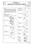
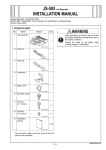
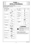
FS-519 Finisher
INSTALLATION MANUAL
Applied Machines: C353/C253/C203/C353P
COLOR MFP (Color/B&W): 35 ppm/35 ppm, 25 ppm/25 ppm, 20 ppm/20 ppm
COLOR PRT (Color/B&W): 35 ppm/35 ppm
Product Code: A02E
Note:
Lifting the machine in an awkward position or
transporting it in a poorly balanced position could
result in personal injury. When transporting the
machine, assign an adequate number of persons
to the job and ensure that each person can take a
good position of not being excessively loaded.
(mass: approx. 33 kg (72-3/4 lb))
No.
Name
Shape
Q’ty
6. Right cover
1
9J08IXC007DA
7. Mounting
bracket A
I. Accessory parts
No.
Name
1
Shape
Q’ty
9J08IXC010DA
1. Finisher unit
8. Mounting
bracket B
1
1
9J08IXC001DA
9J08IXC011DA
2. Tray unit
9. Adjusting plate
4
9J08IXC012DA
10. Exit tray
(upper)
1
1
4349U015AA
11. Retaining plate
1
4349U016AA
12. Label
A01GIXC050DA
3. Secondary
cover
1
1
9J08IXC088DA
9J08IXC004DB
4. Front cover
* Be sure to keep the adjusting plate, which is used
when the machine is not equipped with the paper
feed cabinet and desk.
1
9J08IXC005DA
5. Connector
cover
1
9J08IXC006DA
E-1
A01G-9570-01
No.
Name
Shape
III. Removing protective tape, packing and
other shipping materials
Q’ty
13. Screw A
(4 × 18 mm)
<Finisher unit>
8
Note:
Place the finisher unit beforehand on the table in a
way that the front cover will be off the table.
9J08IXC075DA
14. Screw B
(3 × 8 mm)
2
9J08IXC077DA
15. Screw C
(3 × 8 mm)
3
9J08IXC078DA
16. Screw D
(4 × 8 mm)
2
9J08IXC079DA
17. Screw E
(4 × 8 mm)
1
9J08IXC080DA
A01GIXC003DA
18. Screw F
(3 × 8 mm)
3
1. Remove the protective sheet and tape from the
finisher unit.
9J08IXC081DA
19. Shoulder screw
2
4582U010AA
20. Installation
manual
1
set
4980IXC019DA
A01GIXC004DA
2. Remove the front cover (two screws).
After unpacking, be sure to get rid of the
packaging materials and keep them out of
the reach of children.
Putting the head in the plastic bag
involves danger of suffocation.
Note:
When the punch kit and the saddle stitcher are to
be mounted along with the finisher, mount the
punch kit and the creasing unit for the saddle
stitcher to the finisher before mounting the finisher
unit to the machine.
A01GIXC005DA
II. When installing to C353P
This manual provides the illustration of the machine
used as MFP. However, the same installation procedure is used for C353P.
E-2
6. Remove the protective layer.
Note:
Take care so that the mylar will not be bent.
3. Remove the fixing bracket of the front cover (one
screw).
Protective layer
Mylar
A01GIXC006DA
9J08IXC019DC
4. Remove protective tape from different parts of the
front cover.
7. Remove the protective tape on the front side of
the finisher unit.
A01GIXC007DA
9J08IXC020DC
5. Remove three fixing brackets on the left side of
the finisher unit (two screws).
8. Remove two screws at the bottom of the finisher
unit, and remove the fixing bracket.
9J08IXC018DD
9J08IXC021DC
E-3
<Tray unit>
9. Remove the fixing bracket (upper) on the front
side of the finisher unit (two screws).
10. Remove the fixing bracket (lower) on the front
side of the finisher unit (two screws).
1. Raise the box of the tray unit and remove the tray
unit from the box.
Note:
When removing the tray unit from the box, grasp
the tray unit at the areas as shown in the illustration below.
9J08IXC022DC
11. Remove the fixing bracket on the right side of
the finisher unit (two screws).
A01GIXC008DA
9J08IXC023DB
A01GIXC051DA
A01GIXC041DB
E-4
Note:
• Set the tray unit upright on the table to conduct
operation.
• Take care so that the plate spring on the tray
unit will not be bent.
2. Remove protective tape from different parts of the
tray unit.
Note:
Be sure not to remove the stopper until the tray
unit is installed into the main unit.
Plate spring
A01GIXC053DA
Stopper
A01GIXC011DD
A01GIXC055DB
E-5
IV. Installation procedures
3. Remove the fixing bracket of the tray unit (three
screws each).
Screw
1. Turn off the machine and unplug the power cord
from the power outlet.
2. Remove the sub tray of the machine.
* Remove it while pushing the claws of the sub tray
in the direction of the allow ➀ shown on the illustration and unhook.
Screw
➀
A01GIXC013DB
➀
A083IXC006DB
3. Remove the fixing leg and fixing leg cover of the
front left leg only when the paper feed cabinet or
the desk is mounted.
A01GIXC056DA
4. Peel seals off the machine (two seals).
Seal
E-6
A083IXC007DA
8. Align the hole of the finisher unit to the positioning
pin, then set it all the way in.
Note:
• Set it so that the hole indicated in the illustration
will meet the stabilizing pin.
• When carrying the finisher unit, hold the positions as shown on the illustration.
5. Install the mounting bracket A (four screw A’s furnished with the finisher).
Note:
The clearance between the mounting bracket A
and the machine must parallel.
Stabilizing
pin
A01GIXC057DB
Clearance
A01GIXC058DA
Machine
9. Set the tray unit.
Note:
To set the tray unit, use the area of A as a guide.
Mounting
bracket A
9J08IXC082DB
6. When the punch kit and the saddle stitcher are to
be mounted along with the finisher, mount the
punch kit and the creasing unit for the saddle
stitcher to the finisher.
Note:
For the punch kit and the saddle stitcher mounting
procedures, see installation manual for them.
A01GIXC059DA
7. Remove the job separator (JS-505) if it is
mounted on the machine.
Note:
For the removal procedure, see the installation
manual for the job separator (JS-505).
A
A01GIXC060DA
E-7
14. Remove the locking tape and the tag.
10. Fix the tray unit to the machine (four screw A’s
furnished with the finisher).
Note:
Adjust the casters to align the screw holes.
A01GIXC064DA
15. Remove the stopper.
A01GIXC061DA
11. Install the mounting bracket B (two screw B’s
furnished with the finisher).
Note:
Mount it so that the protruding part will face
upward.
Protruding part
A01GIXC065DA
16. Attach the stopper which was removed in step
15 to the position shown in the illustration.
A01GIXC062DA
12. Remove the exit tray mounting holder and install
two shoulder screws furnished with the finisher.
13. Reinstall the exit tray mounting holder that has
been removed in step 12 (one screw).
A01GIXC066DA
A01GIXC063DA
E-8
17. Pull the lock release lever and remove the finisher from the machine.
19. Install the connector cover (one screw E furnished with the finisher).
* Fit claws (two points) into the slots first.
A01GIXC067DA
A01GIXC023DB
18. Connect the three connectors and a ground wire
(one screw C furnished with the finisher).
Note:
Route the connectors, bundle of harness and
ground wire in a way that one is not placed over
the others, and the space indicated with the circle
on the illustration is secured.
Make sure that the ground wire is not routed over
the connectors (illustration A) and the bundles of
harness do not face downward (illustration B).
20. Install the secondary cover (two screw C’s furnished with the finisher).
Note:
Make sure that there is a uniform clearance
between the misfeed clearing dial and secondary
cover.
A
A01GIXC022DB
<OK>
Bundle of harness
A
A
A
Screw C
Secondary
cover
Misfeed clearing dial
Screw C
Connector
Ground wire
A01GIXC044DA
Illustration A <NG>
A01GIXC046DA
Illustration B <NG>
A: Clearance
A01GIXC045DA
E-9
A01GIXC070DA
21. Install the right cover (two screw D’s furnished
with the finisher).
* Fit claws (three points) into the slots first.
24. Tighten the screws that have been loosened in
step 22.
25. Install the band and the retaining plate to the
front cover (one screw F furnished with the finisher).
26. Close the front cover.
Retaining plate
A01GIXC071DA
22. Loosen two screws and move the hinge up.
23. Set the front cover, and move the hinge down to
fix the front cover.
A01GIXC073DA
27. Push the board box all the way to the lock position.
28. Set the finisher to the machine.
Hinge
Screw
A01GIXC072DA
Board box
A01GIXC074DA
29. Install the upper exit tray (two screw F’s furnished with the finisher)
Note:
To prevent problems, be sure to securely tighten
the screws.
.
A01GIXC075DA
E-10
34. Loosen the two screws (left and right) shown in
the illustration and make the height adjustment.
Then tighten the screws.
30. Connect the hookup cord to the machine.
A01GIXC081DA
31. Measure the width of X.
Specifications: 5 ± 2 mm
Note:
• If X is out of the specified range, follow step 32
and later to adjust the finisher height.
• If X is within the specified range, height adjustment is not required. Move to step 37.
A01GIXC048DA
35. Reinstall the covers that have been removed in
step 33 (two covers).
X
A01GIXC049DA
36. Set the finisher to the machine.
A01GIXC077DA
32. Pull the lock release lever and remove the finisher from the machine.
33. Remove a cover from each stand leg (two
places).
A01GIXC047DA
E-11
37. Measure the width of Y and Z (clearance of the
exterior parts) on front and back side.
Specifications:
Y = Z - 1 mm (Y must be smaller than Z)
Z = 7 ± 2 mm (front side)
Z = 9 ± 2 mm (back side)
Note:
To measure the front side, open the front door and
measure it using finisher side as supporting point
refer to <Front side measuring method> shown on
the illustration below.
39. Affix the labels to the position shown below.
<Reverse automatic document feeder>
Label
A01GIXC037DA
Y
<by the FD original scale>
Z
A01GIXC078DA
<Front side measuring method>
Label
Y
A01GIXC038DA
Z
A01GIXC035DC
38. Lower the left casters until the width of Y and Z
is within the specifications.
* For adjusting the casters, hold the bottom part of
the stand table and turn the adjusting bolt.
Left
Adjusting
bolt
Right
A01GIXC080DA
E-12