1
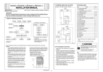
PK-512 Punch Kit
INSTALLATION MANUAL
Applied Machines: FS-517/FS-518/FS-520/FS-607/FS-608/FS-612/FS-531
I. Accessory parts
No.
Name
III. Installation procedures
Shape
1. Open the front door of the Finisher.
2. Remove the control board cover. (1 screw)
3. Remove the guide plate. (2 screws)
Q’ty
1. Punch Kit
1
Guide plate
15KJIXC001SA
2. Punch waste
box
Control board
cover
1
15KNIXC002SA
3. Control board
15KNIXE001SB
1
4. Insert the two of the control board support/1 into
the back side, and insert two into the front side.
Insert the two of the control board support/2 into
the central area of the front side.
A04FIXC001SA
4. Control board
support /1
5. Control board
support /2
4
15KNIXC004SA
2
15KJIXC003SA
Control board
support /1
6. Sensor
assembly wire
bundle
Control board
support /2
1
15KAIXC002SA
7. TP screw
M4x6
4
8. TP screw
M3x6
2
Control board
support /1
9. Installation
manual
15KJIXE001SA
1
II. Preliminary Preparation
1. Turn the machine’s Sub and Main switches OFF,
and unplug the power cord.
2. Remove the finisher if there is one mounted to
the machine.
E-1
A04F955056
5. Making sure the direction is correct, install the
control board on the control board supports.
Note:
When installing the control board, mount it so that
the notched portion of the control board faces the
front.
7. Temporarily tighten the screw (TP screw M3x6: 1
pc.) on the back side of the finisher. Position the
sensor on the sensor assembly wire bundle with
the projection then fasten with the temporarily
tightened screw.
Note:
Make sure pass the sensor assembly wire bundle
on the right side of the sensor.
Sensor assembly wire bundle
Control board
TP screw M3x6
Sensor
Notched portion
A04EIXE001SA
15KAIXE005SB
8. Connect the sensor assembly wire bundle connectors (4 locations) to the control board connectors.
Connector
6. Pass the Punch kit connectors of the sensor
assembly wire bundle through the hole and attach
the wire bundle to the eight wire saddles.
Note:
• Let the control board side connectors hang down
to the bottom.
• Let the first wire bundle of the Punch kit connectors hang out from the hole, as shown in the
figure.
Wire saddles
Connectors
A04EIXE002SA
9. Attach the wire bundle to the four wire saddles.
Wire saddles
Bundled
portion
Wire saddles
A04EIXE003SA
15KJIXE003SA
E-2
(3) Align the markings of the punch kit to the center and secure. (TP screw M4x6: 4 pcs.)
Make sure to open and close the conveyance
guide plate/1 once so that the PET at the entrance
of the punch kit return to normal position.
10. Remove the locking tapes and remove the punch
kit cover. (TP screw M3x6: 2 pcs.)
TP screws M4x6
TP screws M3x6
Markings
15KJIXE007SA
11. Install the Punch kit.
(1) Remove the pin holder. (2 screws)
Note:
Remove the pin holder if it is only installed.
TP screws M4x6
Conveyance guide plate/1
15KJIXE011SB
(4) Connect the two Punch kit connectors to the
Punch kit, and attach the wire bundle to the
two mini wire saddles.
Note:
Arrange the wire bundle at a proper distance from
the gear.
Pin holder
Mini wire saddles
A04FIXE001SA
(2) Make sure the guide pin on the inner side of
the Punch kit go into the guide hole in the Finisher.
Note:
Put the Punch kit wire bundle in the finisher before
inserting the Punch Kit.
Punch kit connectors
15KJIXE012SB
(5) Connect the Punch kit wire bundle to three
connectors on the control board.
Connectors
Punch kit
15KAIXE003SA
A04EIXE004SA
E-3
(6) Attach the Punch kit wire bundle to the four wire
saddles.
14. Install the finisher to the machine.
Note:
• Check that the machine installation plate/ lower
(Finisher accessory parts) hook is securely set
on the finisher when installing the finisher to the
machine.
• Refer to the finisher installation manual for details
on installing the finisher to the machine.
Wire saddles
Lower view
Finisher
Machine
Securely installing
the finisher to the machine.
A04EIXE005SA
12. Align the control board cover with the grooves
and slide in the board, then secure. (1 screw)
A04EIXE006SA
Control board cover
15KJIXE017SA
13. Install the Punch waste box, and close the finisher’s front door.
Punch waste box
15KJIXE018SA
E-4
< for FS-520/FS-607/FS-612/FS-531 >
17. Adjust the skew of the hole punch position.
(1) Insert a piece of paper into the finisher’s interlock to turn it ON.
15. Software DipSW setting.
Step
1. Plug the power cord into the outlet and turn
ON the Main power switch.
2. Enter Service mode.
Note:
Refer to procedures in the Service Manual
to enter into the Service Mode.
3. [Service Mode menu screen]
Touch “System Setting”.
4. Touch “Software SW setting” or ”Software
DIPSW setting”.
5. If 2-3 hole punch kit is installed, set
22-1
1
(ON)
22-2
0
(OFF)
Paper
23-7
1
(ON)
15KJIXE019SA
(2) Turn ON the Main and Sub power switches of
the machine, and make sample copies for both
the single-side and double-side with any tray in
Punch mode.
(3) Using the paper sample, check the hole position gap by folding the paper in half.
(4) If hole position gap is found, loosen the Punch
kit fix screws (TP screw M4x6: 4 pcs.) and
move the punch kit to the left or right to the
amount of the skew.
Note:
When doing so, adjust the gap in the depth direction according to “Adjusting the vertical punch position” on page 8.
If 2-4 hole punch kit is installed, set
22-1
0
(OFF)
22-2
1
(ON)
23-7
1
(ON)
And touch “Return”.
6. Turn OFF the Sub power switch and Main
power switch.
16. Paper edge detect sensor adjustment.
Step
1. Turn ON the Main power switch.
2. Enter Service mode.
Note:
Refer to procedures in the Service Manual to
enter into the Service Mode.
3. [Service Mode Menu screen]
Touch “Finisher Adjustment”.
4. [Finisher Adjustment Menu screen]
Touch “Punch Adjustment”.
5. [Punch Adjustment Menu screen]
Touch “PaperEdgeDetectSensorAdj.” or
”Paper Edge Detect Sensor".
6. Touch “Start”.
7. When adjustment is done correctly, message
of “Completed” is indicated.
8. Turn OFF the Sub power switch and Main
power switch.
TP screw M4x6
TP screws M4x6
When wide in back
When wide in front
Output samples
15KJIXE020SA
E-5
18. Adjust the skew of the hole punch position.
(When PI-502 is installed to the finisher)
(1) Make sample copies from the PI-502 in Punch
mode.
(2) Using the paper sample, check the hole position gap by folding the paper in half.
(3) If hole position gap is found, loosen the finisher
guide plate fixing screw and move it to the left
or right to the amount of the skew.
20. Install the Punch kit cover. (TP screw M3x6: 3 pcs.)
Note:
When installing the Punch kit cover, be careful not
to get the wire bundles caught in it.
Punch kit cover
Finisher/front
Guide plate
fixing screw
TP screws M3x6
15KJIXE023SA
21. Pull out the paper nipped by the interlock and
close the finisher’s front door.
When wide in front
When wide in back
Adjusting PI-502 centering
1. Preliminary preparations before adjustment
(1) Place paper in the upper and lower trays of the
PI-502, and make sample copies using the
cover sheet in Punch mode. Check that the
punching hole is within the sensor area when
the hole is punched.
(For upper and lower trays)
* See the figure for item 19 on page E-6.
(2) If there is a gap, execute the following procedure to adjust it.
2. Adjustment procedures
Output samples
15KJIXE021SA
19. Centering adjustment.
Execute for each paper size and tray.
(1) Make sample copies in Punch mode to check
that the punching hole is within the sensor area
when the hole is punched. (For all trays)
(2) If punching position gap is found, adjust the centering of the tray. (Refer to the Service manual)
Step
1. Release the hook and remove the adjustment
cover of the side guide board/back.
Adjustment cover
Punching position
should be in this range
Side guide board
/back
Sensor
Hook
15KJIXE022SA
15KNIXE012SA
E-6
Step
Step
9. Place A4 or 8.5x11 paper by short edge feeding in the cover sheet tray, and adjust the cover
sheet tray size in [Service Mode].
Note:
If the side guide board/back slides too much,
first adjust the cover sheet tray size in [Service Mode] as described in step 9, and then
start from step 2 again.
2. For the lower tray, remove the 2 side guide
board/back mounting screws and slide it to the
right to remove the side guide board/back.
IV. Adjustment
Implement adjustments if parameters do not have
appropriate values.
Side guide board
/back
Adjusting the horizontal punch position
Mounting
screws
1. Standard values
It is possible to adjust up to ± 5 mm from the standard value (the distance between the edge of the
paper and the center of the hole).
Standard hole positions
15KNIXE013SA
3. Loosen the 2 adjustment screws on the side
guide board/back, and slide the side guide
board/2 to twice the distance of the punch hole
gap. (Example: if holes are centered 1.5mm to
the back, slide the board back 3mm.)
Gradation: 2mm.
A
2-4 hole
2-3 hole
A
10.5
9.5
A
A
Side guide board/2
15KAIXE008SA
2. Adjustment procedures
Adjustment
screws
Step
1. Enter Service mode.
Note:
Refer to procedures in the Service Manual
to enter into the Service Mode.
15KNIXE014SA
4. Tighten the 2 adjustment screws securely to
fix side guide board/2.
2. [Service Mode Menu screen]
Touch “Finisher Adjustment”.
5. Install the side guide board/back in the lower
tray.
Note:
When tightening the 2 mounting screws,
make sure that screw torque doesn’t exceed
5kg • cm.
3. [Finisher Adjustment Menu screen]
Touch “Punch Adjustment”.
4. [Punch Adjustment Menu screen]
Touch “Horizontal Position Adj.”.
Select “PI tray” or “Main tray” or select ”PI
Tray” or ”Main Bady Tray”.
6. Place paper in the tray and adjust the side
guides. Make sure that the side guide board/
back is parallel to the paper.
5. Touch “COPY” or “Print Mode“ to display the
Copy Screen. Load the paper on a PI or machine
tray, and make a sample copy. Check the punch
horizontal position of the sample copy.
7. Repeat steps 2 to 6 until punch hole centering
error is eliminated.
6. Touch “SERVICE” or “Exit PrintMode“ to return
to [Punch Adjustment <Horizontal position
adjustment> screen].
8. Install the adjustment cover on the side guide
board/back.
7. If the punch horizontal position is not appropriate, use the numerical keys on the screen
to enter adjusting values (appropriate values), and touch “<<SET” or ”Set”.
(Setting range: -50 to +50 1 step = 0.1mm)
E-7
Step
Step
8. Make another sample copy.
4. Touch “SERVICE” or ”Exit PrintMode” to return
to [Punch Adjustment <Registration adjustment> screen].
9. Repeat steps 5 to 8 until the punch horizontal position is appropriate.
5. If the punch registration is not appropriate,
use the numerical keys on the screen to
enter adjusting values (appropriate values),
and touch “<<SET” or ”Set”.
(Setting range: -20 to +20 1 step = 0.8mm)
10. Touch “Return” to return to the [Punch Adjustment Menu] screen.
Adjusting the punch registration
6. Make another sample copy.
Note:
This adjustment is performed when the punch hole
positions are skewed.
1. Adjustment for machine punch registration amount
• Main Body/reverse
• Main Body/ADU
7. Repeat steps 3 to 6 until the punch registration size of PI1 tray is appropriate.
8. Place paper in the PI2 tray.
9. Repeat steps 3 to 6 until the punch registration size of PI2 tray is appropriate.
Step
10. Touch “Return” to return to the [Punch Adjustment Menu] screen.
1. [Punch Adjustment Menu screen]
Touch “Registration Adjustment”. Check that
“Main Body/reverse” is highlighted.
2. Touch “COPY” or ”Print Mode” to display the
Copy Screen. Load the paper on the tray,
and make a sample copy. Check the punch
registration of the sample copy.
3. Touch “SERVICE” or ”Exit PrintMode” to return
to [Punch Adjustment <Registration adjustment> screen].
4. If the punch registration is not appropriate,
use the numerical keys on the screen to
enter adjusting values (appropriate values),
and touch “<<SET” or ”Set”.
(Setting range: -20 to +20 1 step = 0.8mm)
5. Make another sample copy.
6. Repeat steps 2 to 5 until the punch registration size of Main Body/reverse is appropriate.
7. Touch “Main Body/ADU”.
8. Touch ‘COPY” or ”Print Mode”, make a
punch registration sample copy on the copy
screen, and check the punch registration
size.
9. Repeat steps 2 to 5 until the punch registration size of Main Body/ADU is appropriate.
2. Adjustment for PI-502 punch registration amount
• PI1 Tray
• PI2 Tray
Step
1. [Punch Adjustment <Registration Adjustment>
screen]
Touch “PI1 Tray”.
2. Place paper in the PI1 tray.
3. Touch ‘COPY” or ”Print Mode”, make a
punch registration sample copy on the copy
screen, and check the punch registration
size.
E-8
Adjusting the vertical punch position
< for FS-517/FS-518/FS-608 >
1. Standard value
• It is possible to adjust the B dimension of half of
the top and bottom by ±5mm from the standard
value.
• It is not possible to adjust the B value of the distance between holes.
Standard hole positions
15. Punch Option Setting.
Step
1. Turn ON the Main and Sub power switches
of the machine.
2. Enter Service mode.
Note:
Refer to procedures in the Service Manual
to enter into the Service Mode.
Top and bottom center gap
B
2-4 hole
80 0.5
2-3 hole (2 hole) 70 0.5
(3 hole) 108 0.5
Top and bottom B
dimension 1/2 1
3. [Service Mode screen]
Touch “Finisher”.
4. [Finisher screen]
Touch “Punch option setting”.
B
B
B
5. Touch “PK-512”. Check 2-Holes/3-Holse or
2-Holes/4-Holse is highlighted and touch
“decision”.
B
B
B
6. Turn OFF the Sub power switch and Mainpower switch.
15KAIXE009SA
2. Adjustment procedure
Step
16. Punch edge detection setting.
1. [Punch Adjustment Menu screen]
Touch “Vertical Position Adj.”.
Step
2. Select the paper size to be adjusted.
1. Turn ON the Main and Sub power switches
of the machine.
3. Touch “COPY” or ”Print Mode” to display the
Copy Screen. Load the paper of size to be
adjusted on the tray, make a sample copy.
Check the punch vertical position of the
sample copy.
2. Enter Service mode.
Note:
Refer to procedures in the Service Manual
to enter into the Service Mode.
4. Touch “SERVICE” or ”Exit PrintMode” to return
to [Punch Adjustment <Vertical position
adjustment> screen].
3. [Service Mode screen]
Touch “Finisher”.
4. [Finisher screen]
Touch “FS-FN adjustment”.
5. If the punch vertical position is not appropriate, use the numerical keys on the screen to
enter adjusting values (appropriate values),
and touch “<<SET” or ”Set”.
(Setting range: -50 to +50 1 step = 0.1mm)
5. Touch “Punch edge detection”.
6. Press the start key and check whether the
result is “OK”.
Note:
If the “NG” appears, check the install condition again.
6. Make another sample copy.
7. Repeat steps 3 to 6 until the punch vertical
position is appropriate.
7. Touch “OK” twice to return to the [Service
mode Screen].
8. Repeat the same operation about other sizes.
8. Touch “Exit” on the Service mode Screen.
9. Turn OFF the Sub power switch and Mainpower switch.
E-9
17. Adjust the skew of the hole punch position.
(1) Insert a piece of paper into the finisher’s interlock to turn it ON.
18. Adjust the skew of the hole punch position.
(When PI-503 is installed to the finisher)
(1) Make sample copies from the PI-503 in Punch
mode.
(2) Using the paper sample, check the hole position gap by folding the paper in half.
(3) If hole position gap is found, loosen the finisher
guide plate fixing screw and move it to the left
or right to the amount of the skew.
Finisher/front
Guide plate
fixing screw
Paper
15KJIXE019SA
(2) Turn ON the Main and Sub power switches of
the machine, and make sample copies for both
the single-side and double-side with any tray in
Punch mode.
(3) Using the paper sample, check the hole position gap by folding the paper in half.
(4) If hole position gap is found, loosen the Punch
kit fix screws (TP screw M4x6: 4 pcs.) and
move the punch kit to the left or right to the
amount of the skew.
Note:
When doing so, adjust the gap in the depth direction according to “Adjusting the vertical punch position” on page 13.
TP screw M4x6
When wide in front
When wide in back
Output samples
15KJIXE021SA
19. Centering adjustment.
Execute for each paper size and tray.
(1) Make sample copies in Punch mode to check
that the punching hole is within the sensor area
when the hole is punched. (For all trays)
(2) If punching position gap is found, adjust the centering of the tray. (Refer to the Service manual)
Punching position
should be in this range
TP screws M4x6
When wide in back
When wide in front
Sensor
15KJIXE022SA
Output samples
15KJIXE020SA
E-10
20. Install the Punch kit cover. (TP screw M3x6: 3 pcs.)
Note:
When installing the Punch kit cover, be careful not
to get the wire bundles caught in it.
Step
2. For the lower tray, remove the 2 side guide
board/back mounting screws and slide it to the
right to remove the side guide board/back.
Punch kit cover
Side guide board
/back
Mounting
screws
TP screws M3x6
15KJIXE023SA
15KNIXE013SA
21. Pull out the paper nipped by the interlock and
close the finisher’s front door.
Adjusting PI-503 centering
1. Preliminary preparations before adjustment
(1) This adjustment is performed when the cover
sheet feeder adjustment for PI-503 is finished.
* See the install manual for PI-503 to check
how to make the adjustment.
(2) Place paper in the upper and lower trays of the
PI-503, and make sample copies using the
cover sheet in Punch mode. Check that the
punching hole is within the sensor area when
the hole is punched.
(For upper and lower trays)
* See the figure for item 19 on page E-10.
(3) If there is a gap, execute the following procedure to adjust it.
2. Adjustment procedures
Step
Side guide board/2
Adjustment
screws
15KNIXE014SA
1. Release the hook and remove the adjustment
cover of the side guide board/back.
4. Tighten the 2 adjustment screws securely to
fix side guide board/2.
5. Install the side guide board/back in the lower
tray.
Note:
When tightening the 2 mounting screws,
make sure that screw torque doesn’t exceed
5kg • cm.
Adjustment cover
Side guide board
/back
3. Loosen the 2 adjustment screws on the side
guide board/back, and slide the side guide
board/2 to twice the distance of the punch hole
gap. (Example: if holes are centered 1.5mm to
the back, slide the board back 3mm.)
Gradation: 2mm.
6. Place paper in the tray and adjust the side
guides. Make sure that the side guide board/
back is parallel to the paper.
Hook
7. Repeat steps 2 to 6 until punch hole centering
error is eliminated.
8. Install the adjustment cover on the side guide
board/back.
9. Place A4 or 8.5x11 paper by short edge feeding in the cover sheet tray, and adjust the cover
sheet tray size in [Service Mode].
15KNIXE012SA
E-11
IV. Adjustment
Adjusting the punch registration
Make a copy in the punch mode.
Note:
If any of the items below is out of specification,
make an adjustment following their corresponding
adjustment method.
Note:
This adjustment is performed when the punch hole
positions are skewed.
1. Adjustment for machine punch registration amount
Step
Adjusting the horizontal punch position
1. Turn ON the Main and Sub power switches
of the machine.
1. Standard values
It is possible to adjust up to ± 5 mm from the standard value (the distance between the edge of the
paper and the center of the hole).
Standard hole positions
2. Enter Service mode.
Note:
Refer to procedures in the Service Manual
to enter into the Service Mode.
A
2-4 hole
2-3 hole
A
3. [Service Mode screen]
Touch “Finisher”.
10.5
9.5
A
4. [Finisher screen]
Touch “FS-FN adjustment”.
A
5. Touch “Punch Resist Loop Size(Body)”.
6. Enter adjusting values with [+] or [-].
(Setting range: -16.0 to +16.0 mm
1step = 0.8mm )
If punched holes are not aligned, enter the
value of [+] to adjust misalignment.
If this does not resolve the misalignment
problem or this causes wrinkles on paper,
enter the value of [-].
15KAIXE008SA
2. Adjustment procedures
Step
1. Turn ON the Main and Sub power switches
of the machine.
7. Touch “OK” twice to return to the [Service
mode Screen].
2. Enter Service mode.
Note:
Refer to procedures in the Service Manual
to enter into the Service Mode.
8. Touch “Exit” on the Service mode Screen.
9. Turn OFF the Sub power switch and Mainpower switch.
10. Make a copy again and check the deviance
of punch hole position.
3. [Service Mode screen]
Touch “Finisher”.
4. [Finisher screen]
Touch “FS-FN adjustment”.
2. Adjustment for PI-503 punch registration amount
Step
5. Touch “Punch Horizontal Position”.
1. Turn ON the Main and Sub power switches
of the machine.
6. Check the “Main body” is displayed in
reversed.
2. Enter Service mode.
Note:
Refer to procedures in the Service Manual
to enter into the Service Mode.
7. Enter adjusting values with [-] or [+].
Setting range :
-5.0 to +5.0mm 1step=0.1mm
• To make width a greater :
Enter the Value of [+]
• To make width a smaller :
Enter the Value of [-]
3. [Service Mode screen]
Touch “Finisher”.
4. [Finisher screen]
Touch “FS-FN adjustment”.
8. Touch “OK” twice to return to the [Service
mode screen].
5. Touch “Punch Resist Loop Size(PI)”.
9. Touch “Exit” on the Service mode Screen.
6. Touch “Upper”.
10. Turn OFF the Sub power switch and Mainpower switch.
11. Make a copy and check the punch hole positions again.
E-12
Step
7. Enter adjusting values with [+] or [-].
(Setting range: -16.0 to +16.0 mm
1step = 0.8mm )
If punched holes are not aligned, enter the
value of [+] to adjust misalignment.
If this does not resolve the misalignment
problem or this causes wrinkles on paper,
enter the value of [-].
Adjusting the vertical punch position
1. Standard value
• It is possible to adjust the B dimension of half of
the top and bottom by ±5mm from the standard
value.
• It is not possible to adjust the B value of the distance between holes.
Standard hole positions
Top and bottom center gap
B
2-4 hole
80 0.5
2-3 hole (2 hole) 70 0.5
(3 hole) 108 0.5
8. Touch “Lower” to make an adjustment referring to the step 6 to 7.
Top and bottom B
dimension 1/2 1
9. Touch “OK” twice to return to the [Service
mode Screen].
10. Touch “Exit” on the Service mode Screen.
B
11. Turn OFF the Sub power switch and Mainpower switch.
B
12. Make a copy again and check the deviance
of punch hole position.
B
B
B
B
15KAIXE009SA
2. Adjustment procedure
Step
1. Turn ON the Main and Sub power switches
of the machine.
2. Enter Service mode.
Note:
Refer to procedures in the Service Manual
to enter into the Service Mode.
3. [Service Mode screen]
Touch “Finisher”.
4. [Finisher screen]
Touch “FS-FN adjustment”.
5. Touch “Punch Vertical Position”.
6. Check the “Main body” is displayed in
reversed.
7. Enter adjusting values with [-] or [+].
(Setting range : -5.0 to +5.0mm
1step=0.1mm)
• To make hole position upper:
Enter the value of [+]
• To make hole position lower:
Enter the value of [-]
8. Touch “OK” twice to return to the Service
mode Screen.
9. Touch “Exit” on the Service mode Screen.
10. Turn OFF the Sub power switch and Mainpower switch.
11. Make a copy and check the punch hole positions again.
E-13