1
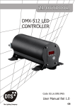
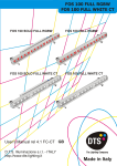
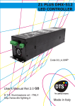
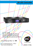
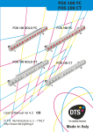
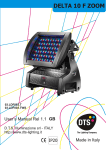
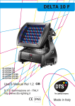
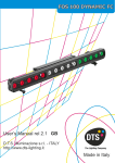
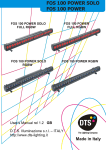
Z1 PLUS IP65
DMX-512 LED CONTROLLER
Datasheet
Code 03.LA.009P.IP65
User’s Manual Rel 2.0 GB
D.T.S. Illuminazione srl - ITALY
http://www.dts-lighting.it
Made in Italy
2
Z1 PLUS IP65
IMPORTANT SAFETY INFORMATION
Fire prevention:
Never locate the fixture on any flammable surface.
Minimum distance from flammable materials: 10 cm
Replace any blown or damaged fuses only with those of identical value
Prevention from electric shock:
High voltage is present inside the unit.
Unplug the unit prior to performing any operation which involves touching the inside of the unit.
This equipment must be grounded, do not connect to non-grounded supplies.
The use of a thermal magnetic circuit breaker is recommended for each Z1 PLUS IP65.
Use only AC supplies 90-260V, 50-60Hz
The unit should never be located in position exposed to rain or in areas of extreme humidity.
A good air ventilation is essential for proper equipment work.
Safety:
The external surface of the unit may exeed 50°C; never handle the unit until at least 5 minutes have
elapsed since the unit was turned off.
Never install the unit in an enclosed area lacking sufficient air flow.
The ambient temperature should not exeed 40°C and should not be lower than -10°C
DESCRIPTION:
Z1 PLUS IP65 is a full-range AC 90-260 V, 50-60 Hz power supply unit dedicated specifically for use
with DTS products featuring LED technology.
Z1 PLUS IP65 can control set-ups of D.T.S. LED products in various combinations.
Z1 PLUS IP65 can be used in Master or Slave mode; ample networks of interconnected Z1 units can
be created: * max 32 slave units for each master.
Z1 PLUS IP65 can also be remote-controlled using the USITT DMX 512 standard digital
communication protocol.
Z1 PLUS IP65 guarantees a full level of IP65 protection against infiltrations of solids and liquids,
allowing it to be used safely both indoors and outdoors.
MAIN ELECTRICAL CHARACTERISTICS:
Input Voltage Range : Vin 90 - 260 Vac
Frequency : 50 - 60 HZ
Power Consumption Range : 8 - 100 W
Power Factor ( Pf) : 0.95 electronic PFC controller
Efficiency : 90% typical
IP protection grade: IP 65
Output:
Power Output Range : 6 - 100W per output, 1,5 - 25W per channel
Output Current : 350 mA @ 100% per channel (500mA @ 100% per channel in BOOST Mode)
Output Voltage : Vout 48V
Max Load (output) :15 x FOCUS RGB LED projectors or 15 x MR16 RGB LED lamps or 5 x FOCUS
FULL RGBW / FULL WHITE LED projector or 5 x MR16 FULL RGBW / FULL WHITE LED lamp or
1 x HELIOS R all models LED projector or 1 x TITAN HEAD all models LED projector or 1 x RA7 HEAD
all models LED projector or 1 x HORUS all models LED projector or 1 x FOS 100 Plus all models led bar,
or 3 x FOS 33 Plus all models led bars.
Min Load (output) : 1 x MR16 RGB LED lamp
Control Input:
Control Signal : DMX 512
Dimming System :Constant Current PWM
Address Range : DMX 512 channels addressable by display
APPLICATIONS:
Cinemas - Restaurants and pubs - Discoteques - Architectural - Interior and Exterior.
Z1 PLUS IP65
3
INPUT/OUTPUT CONNECTIONS
Mains 90-260 Vac
50-60 Hz male
connector
DMX IN/OUT
Female
Connector
LED OUTPUT cable (30 cm lenght)
with M12 female cable connector
DMX IN/OUT
Female
Connector
M12 LED output
Female connector
on board Z1 PLUS IP65
2
3
MAINS
DMX IN-OUT
MALE CONNECTOR
FEMALE CONNECTOR
4
8
Pin1 7 6
5
4
1
3
2
Display
4
Z1 PLUS IP65
WIRING DIAGRAM
Z1 PLUS IP65 is provided with an M12 female cable connector (30cm cable lenght).
M12 LED input
Male cable connector
on board FOS /
TITAN HEAD /
RA7 HEAD UNITS
4
5
6
3
M12 LED output
Female cable connector
on board Z1 PLUS IP65
2
2
8
7 Pin1
3
1-RED +
(FC / RGBA / WHITE)
2-RED (FC / RGBA / WHITE)
3-GREEN + (FC / RGBA / WHITE)
4
8
Pin1 7 6
M12 LEDS
CONNECTOR PINOUT
5
4-GREEN - (FC / RGBA / WHITE)
5-BLUE + (FC / RGBA / WHITE)
6-BLUE - (FC / RGBA / WHITE)
7-AMBER - (RGBA / WHITE)
78-AMBER + (RGBA / WHITE)
For application where IP65 rating is not necessary, Z1 PLUS IP65 cabling connection
can be done with a standard UTP TIA/EIA 568-B2 category 5E cable.
The maximum distance between power supply and the last unit on the line should not
exceed 100 meters.
For IP65 rating application, D.T.S. reccomed the use of a IP65/68 cable as the
8XAWG24 multipolar black outdoor cable (IP68) (D.T.S. Code: 0509C062).
The maximum distance between power supply and the last unit on the line should not
exceed 100 meters.
5
Z1 PLUS IP65
DMX SIGNAL CONNECTION:
The unit operates using a digital DMX 512 signal. Connection between the controller and the unit or
between units must be carried out using a two pair screened ø0.5 mm.
Ensure that the conductors do not touch each other. Do not connect the cable ground to the DMX
connector chassis. The plug housing must be isolated. Connect the mixer signal to the DMX IN
projector plug and connect it to the next projector by connecting the DMX OUT plug on the first unit to
the DMX IN plug of the second one.
In this way, all the projectors are cascade connected.
CONTROLLER
S TA N D A R D
DMX 512
5
1
4
2
1=GND
2=DATA3=DATA+
3
P.S:
If the display showing the DMX address flashes, then one of the following errors has occurred:
- DMX signal not present
- DMX reception problem
For Installations where long distance DMX cable connections are needed, we suggest to use a DMX
terminator.
The DMX terminator is a male DMX cable connector with a 120 ohm resistor Between pin 2 and 3.
The DMX terminator must be plugged into the DMX out panel connector of the last unit connected to
the DMX line.
DMX
MALE CABLE
CONNECTOR
120 OHM
PLACE A 120 OHM RESISTOR BETWEEN PIN 2
AND 3 OF A MALE DMX CONNECTOR AND PLUG IT
INTO THE DMX OUT PANEL CONNECTOR OF THE
LAST UNIT CONNECTED TO THE DMX LINE
6
Z1 PLUS IP65
DMX ADDRESS
Z1 PLUS IP65 can be used in seven different modes: 10 DMX channels mode (default), 15 DMX
channels mode (Dimmer + RGBW channels 16 bit), 6 DMX channels mode (Shutter + Dimmer +
RGBA), WALL mode (6 DMX channels; for use with DTS Wall mounted DMX controller 0514L007),
M4CH mode (5 DMX channels; Dimmer + RGBA), RGBA mode (4 channels), 1 DMX channel
mode.
If you want to use the Z1 RGB in 6 channels mode, select the 6 CH mode from the MODE menu
and set the following addresses on the mixer: (To be used only with DTS Wall mounted
DMX controller 0514L007)
Projector
Projector
Projector
…..
projector
1
2
3
6
A001
A009
A017
A….
A041
If you want to select the next projector, just add “8”
DTS Wall mounted DMX controller 0514L007 assign 8 DMX
channels per unit also if some channels are not used
If you want to use the Z1 PLS IP65 in 10 channels mode, select the 10 CH mode from the MODE
menu and set the following addresses on the mixer:
Projector
Projector
Projector
…..
projector
1
2
3
6
A001
A011
A021
A….
A051
If you want to select the next projector, just add “10”
Selelcting the DMX address
1) Press the UP-DOWN key until you reach the required DMX address. The numbers on the
display will start to flash (but the new DMX address hasn't yet been set).
2) Press ENTER to confirm your selection. The numbers on the display will stop flashing and the
projector is now controlled by the new DMX address.
TIPS: if you keep pushed the UP or DOWN keys, the channels are calculated more quickly and
you get a faster selection.
Z1 PLUS IP65
7
DISPLAY FUNCTIONS
MENU
ENTER
DOWN
UP
DISPLAY FUNCTIONS
The Z1 PLUS IP65 display panel shows all the available functions . Using these functions, it is possible
to change some of the parameters and add some functions. Changing the D.T.S. setting can vary the
functions of the unit so that it does not respond to the DMX 512 signal used to control it. Carefully
follow the instructions below before carrying out any variations or selections.
NOTE: the symbol
shows which key has to be pushed to obtain the desired function.
Software version 5.09
MENU
Up-Down
ENTER
REVERSE DISPLAY
Reverses display's reading depending on
the mounting position (on the ground or
suspended).
Up-Down
ENTER
Floor
position
Up-Down
Suspension
position
Display OFF
Up-Down
DISPLAY STAND BY
To turn off the display (after 5 seconds)
or leave it always on.
Up-Down
ENTER
DMX MODE
To select DMX mode : 10 DMX channels
mode (default),15 DMX channels mode
(Dimmer + RGBW channels 16 bit),
6 DMX channels mode (Shutter +
Dimmer + RGBA), WALL mode (6 DMX
channels; for use with DTS Wall
mounted DMX controller 0514L007),
M4CH mode (5 DMX channels; Dimmer
+ RGBA), RGBA mode (4 channels), 1
DMX channel mode.
CUSTOM DMX mode let you set the
parameters for Shutter, Dimmer, Red,
Green, Blue, Amber, Ctc, Macro and
Function to the desired DMX channels.
(not yet implemented)
AUX mode let you activate an external
ON -OFF control on IR connector.
(not implemented on Z1 PLUS IP65)
Display
always ON
Up-Down
Up-Down
Up-Down
Up-Down
Up-Down
Up-Down
Up-Down
Up-Down
ENTER
6 CHANNELS
ENTER
1 CHANNEL
ENTER
RGBA (4 CHANNELS)
6 CHANNELS
M4CH (5 CHANNELS)
15 CHANNELS
ENTER
Up-Down
ENTER
Up-Down
ENTER
ENTER
ENTER
Dimmer + RGBA
ENTER
ENTER
Dimmer + RGBW channels 16
bit
ENTER
Up-Down
AUX MODE
ENTER
Default DMX Mode = 10 CH
10 CHANNELS
Up-Down
MACRO
MACRO Function, enable channel
mapping macro rainbow effects
STD (default)
ENTER
Up-Down
ENTER
MENU
ENTER
ENTER
Custom mode enabled
(not yet implemented
External ON - OFF control on IR
connector (not implemented on z1
plus ip65)
ENTER
ENTER
Standard mode enabled:
(Default).
Extended mode enabled:
Rainbow effects on MACRO
channel.
Z1 PLUS IP65
8
Default = 0
MENU
Up-Down
ENTER
LED
RGBA Min/Max, Smooth, Compression,
Sync and Boost level values settings
Up-Down
ENTER
Up-Down
Default = 100
ENTER
ENTER
Up-Down
Default = 0
ENTER
RGBA MINIMUM VALUES
This menu allow to select the
minimum levels for Red, Green,
Blue and Amber
Up-Down
ENTER
Default = 100
ENTER
Up-Down
Default = 0
ENTER
Up-Down
RGBA MAXIMUM VALUES
This menu allow to select the
maximum levels for Red, Green,
Blue and Amber
ENTER
Default = 100
ENTER
Default = 0
ENTER
Up-Down
These settings have priority on
Master Dimmer
ENTER
Default = 100
ENTER
Up-Down
SMOOTH VALUE
This menu allow to select the value
of the delay (in milliseconds) for
RGBA and Dimmer channels
reaction to DMX or Program
variation.
Off = 25 ms delay (Fast response)
20 = 250 ms delay (Slow response)
COMPRESSION
This menu allow to select between
Linear current output or quadratic
current output for LEDs
Default = Linear
SYNC
This menu allow to adjust the PWM
frequency value (Hz) in order to
reduce flickering in the process of
your camera recordings
ENTER
Up-Down
Range = Off - 20
Default = 4
ENTER
Off = 25 ms
Istant responce to DMX variation
20 = 250 ms
Smooth response to DMX variation
Up-Down
ENTER
Up-Down
Linear = Linear
current output
Quadratic =
Linear light
output
Up-Down
ENTER
Up-Down
Range =
610 Hz -10 KHz
Default = 610 Hz
ENTER
ENTER
ENTER
Boost mode activated
BOOST DRIVING
This menu allow to increase the LED’s
current from 350 mA to 500 mA
ENTER
Up-Down
Up-Down
Boost mode deactivated
ENTER
ENTER
Whit BOOST active,the LED’s
current is set to 500 mA
(30%more gain).
Default = Activated
Z1 PLUS IP65
9
MENU
Up-Down
ENTER
ENTER
Up-Down
ENTER
Up-Down
ENTER
ENTER
Up-Down
ENTER
ENTER
Up-Down
ENTER
AUTOMATIC MODE
Automatic demo game without
DMX controller
ChPr
Chase with 16 steps previously
created in REC MODE
Speed and Wait time selectable
by user
CUPr
RGBA values selectable by user
Rainbow (rAIn)
Rainbow colours effect.
Speed time selectable by user
CU01-CU16
Color Macros as on DMX channel
8 (Macro)
WHITE MACROS
16 macros for White color from
2800 to 6500 ° K
DIMMER
Dimmer level selectable by user
as on DMX channel 2 (Dimmer)
Dimmer level is active for all the
programs and macros
SHUTTER
Shutter level selectable by user
as on DMX channel 1 (Shutter)
Shutter level is active only for
CU01/CU16 and Wh01/Wh16
macros
ENTER
Up-Down
ENTER
Up-Down
ENTER
Up-Down
ENTER
ENTER
ESC
Exit from Automatic Mode Menu
ENTER
Up-Down
ENTER
ENTER
Z1 PLUS IP65
10
MENU
Up-Down
ENTER
ENTER
REC MODE
In DMX Recorder Mode,it is
possible to create and store the
scenes of the ChPr by using an
external DMX controller.
The unit must be setted to 10
channels MODE
DMX Recorder Mode
For the programming of ChPr by using a DMX controller, besides the 10 channels necessary to control the unit a further 3 DMX
channels are needed.
So that in RECORDER mode ( via DMX) the unit will need 13 channels to be correctly programmed.
The three new DMX channels are:
DMX channel 11 = SCENES channel
From 0-10 = no function ( r001)
From 11-255 are displayed the programmable scenes (max 16 scenes from M001 to M0016 )
DMX channel 12 = EDIT channel:
-From 0-19 = no function
-From 20-234 the unit runs the configuration given by the received input DMX values.
With the channel SCENES it is possible to pass from one step to the next while with REC it is possible to record the selected scene.
-From 235-255 the unit runs the configuration given by the received input DMX values closing the sequence as last scene.
With the channel REC it is possible to record the selected scene as last scene.
DMX channel 13 = RECORDING channel
Records the set scene with a variation between 0 to 255 (the display flashes indicating that the scene has been recorded).It is
advised that you keep the REC channel set to 0 and to run through the 255 only once you have decided to save the scene. If ChPr is
not closed, by indicating the last scene ( Edit channel between 235-255), in playback mode all 16 scenes will be played through even
if not programmed
MENU
Up-Down
ENTER
ENTER
ENTER
Up-Down
SLAVE MODE
Slave mode for ChPr program.
All slave units will be
synchronised with master unit,
running their own Chpr program.
MENU
Up-Down
ENTER
Up-Down
ENTER
INFRARED MODE
Infrared remote control.
By activating Ir MODE, it will be
possible to navigate trought the
unit functions by using the D.T.S.
infrared remote control.
D.T.S. Code :0514L008
MENU
Up-Down
NOTE:
External infrared remote sensor
needed.
D.T.S. Code :03.LA.016
Important: IR function is not
Implemented on Z1 PLUS IP65
ENTER
Up-Down
ENTER
Up-Down
ENTER
Fan Speed Control
Range: OFF / 12-24 volt
Default = 18 Volt
FAN SPEED CONTROL
Internal Fan Speed control
selectable by user.
Range: OFF /12-24 volt
Default : 18 Volt
MENU
Up-Down
EMERGENCY
Emergency operating mode.
By setting Emergency mode, it
will be possible to select one of
the 16 preprogrammed WHITE
cues that will then ran if DMX
signal is missing or not available.
Usefull for Emergency EXIT
ilumination on public areas.
ENTER
Up-Down
ENTER
Default = OFF
Default = White 1
ENTER
Default = 255
ENTER
11
MENU
Up-Down
ENTER
Z1 PLUS IP65
ENTER
DEFAULT
To restore default settings
MENU
Up-Down
.
ENTER
ENTER
Internal Unit temperature.
(° Celsius)
TEMPERATURE
Internal Unit temperature
visualisation
MENU
Up-Down
ENTER
ENTER
Up-Down
LIFE TIME
This menu show the total UNIT life time
and the RGBA life time
MENU
Up-Down
ENTER
TEST MODE
RGB colours test with rainbow
MENU
Up-Down
ENTER
. .
SOFTWARE
Software version
SERVICE MENU
For technical personnel only
To operate this menu:
-Connect the unit to the main
-While reset is running, press the MENU and ENTER keys at the same time.
CHANNELS
This menu allow to set 3 channels or 4 channels LEDs output mode
3 LEDs channels output mode = RGB
4 LEDs channels output mode = RGBA / RGBW
PRODUCT MODEL SELECTION:
TITAN PLUS = Default for Z1 PLUS IP65
FOS 100 POWER = only for FOS 100 POWER unit
DELTA 8 = only for DELTA 8 unit
EXIT
Exit from hidden menu.
Z1 PLUS IP65
12
AUTOMATIC OPERATION (AUTO):
Z1 PLUS IP65 can work in automatic mode without a DMX controller. First of all connect the projectors
with a DMX cable (picture below). A maximum quantity of 32 slave units can be connected to the same
Master unit.
MASTER
SLAVE 1
SLAVE 2
SLAVE 3
SLAVE 32
OUT
IN
OUT
IN
OUT
IN
OUT
IN
To activate Auto mode on the first unit, use the menu to run through the different modes until AUTO
appears on the display, and press enter.
Now it is possible to choose between the different pre-programmed games (CUPr-RAIn-CU01/CU16Wh01/Wh16) or ChPr which is user programmable through REC mode. To confirm game activation press
ENTER on the selected GAME.
CUPr-RAIn-CU01/CU16-Wh01/Wh16
The first unit that will work as a Master should be placed in Automatic mode (AUTO), the other units
have to be placed in 10 channels DMX mode (MODE 10 CH) and the DMX address should be set at
A001. For RaIn (rainbow) game it is possible to select the speed for the colour changhing (SPEE).
DIMMER function (in AUTOMATIC MODE) is active for all the programs.
SHUTTER function (in AUTOMATIC MODE) is active only for CU01/CU16 and Wh01/Wh16 macros.
ChPr MASTER/SLAVE
The first unit that will function as a Master must be set to Automatic mode (AUTO), the other units must
be set to Slave mode (SLAV), selectable through the menu. In this way all the Slave units will be
synchronised with the master and running their own ChPr game.
On the master unit it is possible to vary the Speed time (SPEE) for the colour changhing and the Wait
time (UAIt) between the steps.
Speed time and Wait time on the Master, have priority on the slave units.
NB: It is possible to run Ch.Pr on the other units even though these do not have Ch.Pr programmed. You
can do this by setting the units to 10 channels DMX and selecting DMX address A001.
13
Z1 PLUS IP65
Rec mode
It is possible to program your own game on the Z1 PLUS IP65 that will then run it in AUTO mode (ChPr).
Each unit can have its own programmed game.
In REC mode the unit must be set to 10 channels mode.
To program the ChPr by using a DMX controller, you need 3 more channels in addition to the 10 channels
necessary to control the unit.
So that in RECORDER mode (via DMX) the unit will need 13 DMX channels to be correctly programmed.
The three new DMX channels are:
DMX channel 11 = SCENES channel
From 0-10 = no function ( r001)
From 11-255 are displayed the programmable scenes (max 16 scenes from M001 to M0016 )
DMX channel 12 = EDIT channel:
-From 0-19 = no function
-From 20-234 the unit runs the configuration given by the received input DMX values.
With the channel SCENES it is possible to pass from one step to the next while with REC it is possible to
record the selected scene.
-From 235-255 the unit runs the configuration given by the received input DMX values closing the sequence
as last scene.
With the channel REC it is possible to record the selected scene as last scene.
DMX channel 13 = RECORDING channel
Records the set scene with a variation between 0 to 255 (the display flashes indicating that the scene has
been recorded).It is advised that you keep the REC channel set to 0 and to run through the 255 only once
you have decided to save the scene. If ChPr is not closed, by indicating the last scene ( Edit channel between
235-255), in playback mode all 16 scenes will be played through even if not programmed
Z1 PLUS IP65
14
DMX PROTOCOL
10 CHANNELS MODE (Default)
1
2
3
4
5
6
7
8
9
10
SHUTTER
DIMMER
RED
GREEN
BLUE
AMBER
WHITE (Pre-programmed whites at different colour temperatures)
CTC
COLOURS MACRO
FUNCTIONS
DMX CHANNEL
1
DMX range
Value
Mid point
DMX value
0-9
10-19
20-29
30-119
120-149
150-179
180-204
205-229
230-234
235-255
5
14
24
Parameter: SHUTTER
Move
range
(degrees)
Mode
Option
Black-out
Open
Black-out
Strobe at variable speed from slow to fast (3700ms-20ms)
Pulse open at variable speed from slow to fast (42,6s-100ms)
Pulse close at variable speed from slow to fast (42,6s-100ms)
Random Strobe (Master and RGB active)
Random Strobe (Full)
Red, Yellow, Cyan and Blue colour effects at variable speed
Open
192
218
245
DMX CHANNEL
2
DMX range
Value
Mid point
DMX value
Parameter: DIMMER
Move
range
(degrees)
Mode
Option
0-255
DMX CHANNEL
DMX range
Value
0-255
Function
Function
Proportional dimmer
3
Parameter: RED
Mid point
DMX value
Move
range
(degrees)
Mode
Option
Function
Proportional colour
Z1 PLUS IP65
15
DMX CHANNEL
DMX range
Value
4
Parameter: GREEN
Mid point
DMX value
Move
range
(degrees)
Mode
Option
0-255
DMX CHANNEL
DMX range
Value
Proportional colour
5
Parameter: BLUE
Mid point
DMX value
Move
range
(degrees)
Mode
Option
0-255
DMX CHANNEL
DMX range
Value
Function
Proportional colour
6
Parameter: AMBER
Mid point
DMX value
Move
range
(degrees)
Mode
Option
0-255
DMX CHANNEL
Function
Function
Proportional colour
7
Parameter: WHITE (Pre-programmed White at diff. color temperature)
DMX range
Value
Mid point
DMX value
0-55
56-105
106-155
23
80
130
Move
range
(degrees)
Mode
Option
Function
No Function
Full (Red-Green-Blue at Full)
White DTS
IF CHANNEL 10 (FUNCTIONS) = CUSTOM WHITE RECALL (Dmx range value 0 - 79)
156-205
180
Custom White Recall
White CTC (Channel 8 CTC enabled
225
206-255
256 color temp. Correction Macros: 2800°K-6500°K)
IF CHANNEL 10 (FUNCTIONS) = CUSTOM WHITE CREATE (Dmx range value 80 - 160)
156-205
180
Custom White Create (RGB levels selectable by DMX)
206-255
225
White CTC (Channel 8 CTC enabled
256 color temp. Correction Macros: 2800°K-6500°K)
Z1 PLUS IP65
16
DMX CHANNEL
DMX range
Value
8
Parameter: CTC (Color temperature correction)
Mid point
DMX value
Move
range
(degrees)
Mode
Option
Function
IF CHANNEL 7 (White) = WHITE CTC (Dmx range value 206 - 255)
256 color temp. Correction Macros: 0 = 2800°K / 128 = 4500°K / 255 = 6500°K
0-255
IF CHANNEL 7 (White) = NO FUNCTION (Dmx range value 0 - 43)
No Function
0-255
DMX CHANNEL
IF:
MENU Up-Down
DMX range
Value
0-14
15-29
30-44
45-59
60-74
75-89
90-104
105-119
120-134
135-149
150-164
165-179
180-194
195-209
210-225
226-239
240-255
9
Parameter: COLOUR MACROS
ENTER
Up-Down
Mid point
DMX value
Move
range
(degrees)
ENTER Up-Down
Mode
ENTER
Option
PLEASE CHECK PAGE 7
Function
No Function
Macro 1
Macro 2
Macro 3
Macro 4
Macro 5
Macro 6
Macro 7
Macro 8
Macro 9
Macro 10
Macro 11
Macro 12
Macro 13
Macro 14
Macro 15
Macro 16
Z1 PLUS IP65
17
DMX CHANNEL
IF:
MENU Up-Down
DMX range
Value
Parameter: COLOUR MACROS
9
ENTER
Up-Down
Mid point
DMX value
Move
range
(degrees)
Mode
ENTER
Option
PLEASE CHECK PAGE 7
Function
No Function
Macro 1
Macro 2
Macro 3
Macro 4
Macro 5
Macro 6
Macro 7
Macro 8
Macro 9
Macro 10
Macro 11
Macro 12
Macro 13
Macro 14
Macro 15
Macro 16
Rainbow Speed 1 (1 Sec.)
Rainbow Speed 2 (5 Sec.)
Rainbow Speed 3 (10 Sec.)
Rainbow Speed 4 (20 Sec.)
Rainbow Speed 5 (30 Sec.)
Rainbow Speed 6 (60 Sec.)
Rainbow Speed 7 (120 Sec.)
Rainbow Speed 8 (180 Sec.)
Random Speed 1 (0.5 sec.)
Random Speed 2 (1 Sec.)
Random Speed 3 (2 Sec.)
Random Speed 4 (5 Sec.)
Random Speed 5 (10 Sec.)
Random Speed 6 (30 Sec.)
0-14
15-22
23-30
31-38
39-46
47-54
55-62
63-70
71-78
79-86
87-94
95-102
103-110
111-118
119-126
127-134
135-142
143-150
151-158
159-166
167-174
175-182
183-190
191-198
199-206
207-214
215-222
223-230
231-238
239-246
247-255
Parameter: FUNCTIONS (Recall,Create and Store the Custom white)
DMX CHANNEL
10
DMX range
Value
Mid point
DMX value
0-79
80-160
161-255
ENTER Up-Down
Move
Mode
Option
Function
range
(degrees)
Custom White Recall (Enable CH 6 for Custom white Recall)
Custom White Create (Enable CH 6 for Custom white Creation)
Custom White Store (Store the Custom White created )
Z1 PLUS IP65
18
DMX PROTOCOL
6 CHANNELS MODE (Shutter + Dimmer + RGBA)
1
2
3
4
5
6
SHUTTER
DIMMER
RED
GREEN
BLUE
AMBER
DMX CHANNEL
1
DMX range
Value
Mid point
DMX value
0-9
10-19
20-29
30-119
120-149
150-179
180-204
205-229
230-234
235-255
5
14
24
Parameter: SHUTTER
Move
range
(degrees)
Mode
Option
Black-out
Open
Black-out
Strobe at variable speed from slow to fast (3700ms-20ms)
Pulse open at variable speed from slow to fast (42,6s-100ms)
Pulse close at variable speed from slow to fast (42,6s-100ms)
Random Strobe (Master and RGB active)
Random Strobe (Full)
Red, Yellow, Cyan and Blue colour effects at variable speed
Open
192
218
245
DMX CHANNEL
2
DMX range
Value
Mid point
DMX value
Parameter: DIMMER
Move
range
(degrees)
Mode
Option
0-255
DMX CHANNEL
DMX range
Value
0-255
Function
Function
Proportional dimmer
3
Parameter: RED
Mid point
DMX value
Move
range
(degrees)
Mode
Option
Function
Proportional colour
Z1 PLUS IP65
19
DMX CHANNEL
DMX range
Value
4
Parameter: GREEN
Mid point
DMX value
Move
range
(degrees)
Mode
Option
0-255
DMX CHANNEL
DMX range
Value
Proportional colour
5
Parameter: BLUE
Mid point
DMX value
Move
range
(degrees)
Mode
Option
0-255
DMX CHANNEL
DMX range
Value
0-255
Function
Function
Proportional colour
6
Parameter: AMBER
Mid point
DMX value
Move
range
(degrees)
Mode
Option
Function
Proportional colour
Z1 PLUS IP65
20
DMX PROTOCOL
M4CH mode
1
2
3
4
5
(5 DMX channels; Dimmer + RGBA)
DIMMER
RED
GREEN
BLUE
AMBER
DMX CHANNEL
1
DMX range
Value
Mid point
DMX value
Parameter: DIMMER
Move
range
(degrees)
Mode
Option
0-255
DMX CHANNEL
DMX range
Value
Proportional dimmer
2
Parameter: RED
Mid point
DMX value
Move
range
(degrees)
Mode
Option
0-255
DMX CHANNEL
DMX range
Value
DMX range
Value
3
Parameter: GREEN
Mid point
DMX value
Move
range
(degrees)
Mode
Option
DMX range
Value
0-255
Function
Proportional colour
4
Parameter: BLUE
Mid point
DMX value
Move
range
(degrees)
Mode
Option
0-255
DMX CHANNEL
Function
Proportional colour
0-255
DMX CHANNEL
Function
Function
Proportional colour
5
Parameter: AMBER
Mid point
DMX value
Move
range
(degrees)
Mode
Option
Function
Proportional colour
Z1 PLUS IP65
21
DMX PROTOCOL
RGBA mode (4 DMX channels)
1
2
3
4
RED
GREEN
BLUE
AMBER
DMX CHANNEL
DMX range
Value
1
Parameter: RED
Mid point
DMX value
Move
range
(degrees)
Mode
Option
0-255
DMX CHANNEL
DMX range
Value
Proportional colour
2
Parameter: GREEN
Mid point
DMX value
Move
range
(degrees)
Mode
Option
0-255
DMX CHANNEL
DMX range
Value
DMX range
Value
0-255
Function
Proportional colour
3
Parameter: BLUE
Mid point
DMX value
Move
range
(degrees)
Mode
Option
0-255
DMX CHANNEL
Function
Function
Proportional colour
4
Parameter: AMBER
Mid point
DMX value
Move
range
(degrees)
Mode
Option
Function
Proportional colour
22
DMX PROTOCOL
Z1 PLUS IP65
“WALL” 6 CHANNELS MODE (For use with DTS Wall mounted DMX controller 0514L007)
1
2
3
4
5
6
GREEN
RED
BLUE
DIMMER
NOT USED
SHUTTER
DMX CHANNEL
DMX range
Value
MENU
1
Up-Down
ENTER
Up-Down
Mid point
DMX value
Move
range
(degrees)
Mode
Option
2
DMX range
Value
Mid point
DMX value
Parameter: RED
Move
range
(degrees)
Mode
Option
0-255
Parameter: BLUE
3
DMX range
Value
Mid point
DMX value
Move
range
(degrees)
Mode
Option
0-255
Function
Proportional colour
4
Parameter: DIMMER
Mid point
DMX value
Move
range
(degrees)
Mode
Option
0-255
DMX range
Value
Function
Proportional colour
DMX CHANNEL
DMX CHANNEL
Function
Proportional colour
DMX CHANNEL
DMX range
Value
ENTER
Parameter: GREEN
0-255
DMX CHANNEL
6 CHANNELS
Function
Proportional dimmer
5
Parameter: NOT USED
Mid point
DMX value
Move
range
(degrees)
Mode
Option
0-255
Function
No Function
DMX CHANNEL
6
DMX range
Value
Mid point
DMX value
0-9
10-19
20-29
30-119
120-149
150-179
180-204
205-229
230-234
235-255
5
14
24
192
218
245
Parameter: SHUTTER
Move
range
(degrees)
Mode
Option
Function
Black-out
Open
Black-out
Strobe at variable speed from slow to fast (3700ms-20ms)
Pulse open at variable speed from slow to fast (42,6s-100ms)
Pulse close at variable speed from slow to fast (42,6s-100ms)
Random Strobe (Master and RGB active)
Random Strobe (Full)
Red, Yellow, Cyan and Blue colour effects at variable speed
Open
23
Z1 PLUS IP65
LED UNITS WIRING CONNECTIONS
M12 LED
Female cable
connector
on board:
Z1 PLUS IP65
2
3
4
8
5
Pin1 7 6
4
5
6
3
2
8
7 Pin1
M12 LED
Male cable
connector
on board:
FOS 100 PLUS
FOS 100 PLUS ALL MODELS
IMPORTANT:
The maximum number of FOS 100 Plus Led projector connectable to the Z1 PLUS IP65 Power supply
is 1 pcs.
The Maximum distance between the Z1 PLUS IP65 and FOS 100 Plus all models should not exceed
100 meters
NEVER CONNECT NOR DISCONNECT A LED UNIT WHEN THE POWER SUPPLY IS TURNED
ON.
24
Z1 PLUS IP65
LED UNITS WIRING CONNECTIONS
M12 LED
Female cable
connector
on board:
Z1 PLUS IP65
2
3
4
8
5
Pin1 7 6
4
5
6
3
2
8
7 Pin1
M12 LED
Male cable
connector
on board:
FOS 33 Plus
2
M12 FEMALE
FOS 33 ALL MODELS
3
4
5
Pin1 7 6
3
4
2
M12 MALE 5
6
7 Pin1
3
4
2
M12 FEMALE
5
Pin1 7 6
3
4
2
M12 MALE5
6
7 Pin1
IMPORTANT:
The maximum number of FOS 33 Plus Led projector connectable to the Z1 PLUS IP65 Power supply
is 3 pcs.
The Maximum distance between the Z1 PLUS IP65 and the last FOS 33 Plus on the line should not
exceed 100 meters
NEVER CONNECT NOR DISCONNECT A LED UNIT WHEN THE POWER SUPPLY IS TURNED
ON.
25
Z1 PLUS IP65
LED UNITS WIRING CONNECTIONS
M12 LED
Female cable
connector
on board:
Z1 PLUS IP65
3
2
4
8
5
Pin1 7 6
4
5
6
3
2
8
7 Pin1
M12 LED
Male cable
connector
on board:
HELIOS R
HELIOS R ALL MODELS
IMPORTANT:
The maximum number of HELIOS R Led projector connectable to the Z1 PLUS IP65 Power supply is
1 pcs.
The Maximum distance between the Z1 PLUS IP65 and HELIOS R should not exceed 100 meters
NEVER CONNECT NOR DISCONNECT A LED UNIT WHEN THE POWER SUPPLY IS TURNED
ON.
26
NOTES
Z1 PLUS IP65
27
NOTES
Z1 PLUS IP65
The information contained in this publication has been carefully prepared and checked.
However, no responsibility will be taken for any errors. All rights are reserved and this document
cannot be copied, photocopied or reproduced, in part or completely, without prior written consent
from D.T.S.
D.T.S. reserves the right to make any aesthetic, functional or design modifications to any of its
products without prior notice. D.T.S. assumes no responsibility for the use or application of the
products or circuits described herein.
MADE IN ITALY
ISO 9001:2008
D.T.S. quality system
is certified to the
ISO 9001:2008 standard
D.T.S. products are designed
and manufactured at the D.T.S.
plants in italy
*0517I185*
0517I185
D.T.S. Illuminazione s.r.l - Via Fagnano Selve 10-12-14 47843 - Misano Adriatico (RN) Italy
Tel. +39 0541 611131 Fax +39 0541 611111
[email protected] www.dts-lighting.it