1
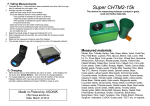
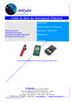
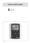
User manual
GT105K-12/Z CONTROL THERMOMETER
Manual number:
IMMU-50-01-12-13-PL
ELECTRONIC SCALES PRODUCER
RADWAG Wagi Elektroniczne, 26–600 Radom, Bracka 28, POLAND
Phone +48 48 38 48 800, fax. +48 48 385 00 10
Sales department: +48 (0-48) 366 80 06
[email protected]
www.radwag.com
DECEMBER 2013
2
Table of CONTENTS
1. BASIC INFORMATION ............................................................................................................ 4
1.1. Intended use ..................................................................................................................... 4
1.2. Precautions ....................................................................................................................... 4
1.3. Warranty conditions ........................................................................................................... 5
1.4. Information included in the user manual ............................................................................ 5
2. UNPACKING ........................................................................................................................... 6
2.1. Unpacking ......................................................................................................................... 6
3. THE CONSTRUCTION ............................................................................................................ 6
4. THE USE ................................................................................................................................. 7
4.1. Turning on and off ............................................................................................................. 7
4.2. Temperature measurement ............................................................................................... 7
5. BATTERY REPLACEMENT .................................................................................................... 9
6. NOTES................................................................................................................................... 10
7. ERRORS DESCRIPTION....................................................................................................... 10
8. TECHNICAL PARAMETRES ................................................................................................. 11
3
1. BASIC INFORMATION
1.1. Intended use
Thermometer is designed to be used for adjustment and control of the drying
temperature in moisture analyzers of RADWAG company production.
Temperature is measured in [°C].
Thermometer enables temperature measurement thanks to a temperature
sensor installed on a cable in a special holder. The holder simulates drying
chamber shield of a moisture analyzer and that is why temperature
measurement during temperature adjustment process and during temperature
test process is carried out in conditions identical with those that occur during
the samples drying process.
CAUTION:
Control thermometer is used for MAY type RADWAG moisture analyzers
and for MAX and MAC moisture analyzers being in production from 6th
June 2013.
1.2. Precautions
A. Before the first use please read the User Manual thoroughly, use the
device according to its intended purposes.
B. Keep the thermometer set in its factory packaging in order to protect it
from any incidental damages.
C. The holder and the thermometer tip can be cleaned with a damp piece
of cloth that was dipped in the alcohol substance. Be careful while
cleaning the set so that not to cause any damage. Be especially careful
while cleaning the measuring tip due to a delicate protective coating of
the sensor. Damaged coating may lead to misleading readings. If the
coating has been damaged it should be repaired by RADWAG
company.
D. The temperature sensor and the shield elements cannot be separated.
E. No liquid or solid substances can be poured into the holder since it
might cause damages.
F. This set can be used only for its intended use, namely to adjust or
control the temperature in a RADWAG moisture analyzers drying
chamber.
G. If no longer used the device and its packaging are to be utilized in
accordance with the current law.
4
1.3. Warranty conditions
A. RADWAG is obliged to repair or replace those parts that turn out to be
faulty as far as production or construction matter is concerned,
B. Defining faulties of unknown origin and setting the ways of their
elimination can be done only in a presence of both, the producer and
the user.
C. RADWAG is not responsible for any damage or loss caused by other
than authorized or proper, regular execution of both, production and
servicing processes,
D. The guarantee does not cover:
• mechanical damages caused by other than regular operation as well
as any thermic, chemic or other random event causes,
• any set damages if the set had not been used in accordance with its
intended use,
• damages caused by media, liquids, water or being a result of a
regular wear and tear,
• maintenance (cleaning),
• the battery replacement.
E. The warranty becomes invalid when:
• the repair is carried out in other service point than the authorized
one,
• the service states intrusion of unauthorized persons,
• the device had not been used in accordance with its intended use.
F. Detailed warranty conditions are to be found in the warranty card
supplemented to the product.
G. Authorized Service phone number is (0-48) 384 88 00 extension 106
and 107.
1.4. Information included in the user manual
The instruction must be read carefully even if the user is experienced in
operating similar devices.
5
2. UNPACKING
2.1. Unpacking
Control thermometer set is placed in a factory packaging.
One must unpack it and take the set out of the equipped with sponge
cushions case.
It is indispensable to keep the set in the case when it is not used.
3. THE CONSTRUCTION
A special extra set with which the moisture analyzer is equipped with
serves to calibrate the temperature.
1.
2.
3.
4.
Thermometer head with the LCD display
The nut closing the battery compartment
Thermometer measuring tip
The thermometer holder together with the holder shield
The thermometer tip is made of OH18N9 stainless steel, it is blackened.
The sensor is calibrated in the factory and the calibration parametres are
stored in the integrated circuit of the device placed in the thermometer head.
The stored parametres do not depend on the power supply.
The whole set can be calibrated on the clients request – to be treated as an
extra order. In such a case a calibration certificate is awarded.
6
Measuring tip is connected to a thermometer head with the use of a silicone
cable resistant to temperatures ranging from -60°C to 200°C. If the cable
touches surface of lower or higher temperature its insulation can be damaged.
Functions:
Automatic turn-off system disables the battery from becoming flat.
„HOLD” function (keeps the readout on the screen).
Supplied with batteries 3x1.5V (Lr44).
CE marking.
4. THE USE
Thermometer assembling into the moisture analyzer and the usage
(adjustment and the test) are described in the user manual of the moisture
analyzer.
4.1. Turning on and off
After pressing the ON/OFF button the device turns on and the display shows
all the symbols for a moment.
This is the display test. After about 2 seconds some of the symbols disappear
and the device turns to the temperature measuring mode.
The device turns off automatically after 10 minutes of not being used (if no
buttons have been pressed) or after pressing the ON/OFF button.
4.2. Temperature measurement
After the startup the thermometer measures the temperature in [°C]. Place the
set in a drying chamber in order to execute the measurement (the description
of such a procedure is to be found in the moisture analyzer user manual), turn
the thermometer on, wait until the displayed value stabilizes and read the
result. Remember that a sensor reaction time depends on a mass of the
measuring element casing (the whole tip temperature has to stabilize).
7
How to assemble the set inside a drying chamber is to be read beneath,
moisture analyzer of MAY series has been used as an example.
Step 1.
Take the following elements out
of the drying chamber:
• disposable drying pan
• drying pan handle
• drying pan bracket
• chamber shield
Step 2.
Place the set elements in a
drying chamber:
• set shield
• and set holder together
with the thermometer
8
Step 3.
After the assembling process
close the drying chamber and
carry out the temperature
calibration process.
CAUTION: All the steps must be carefully carried out so as not to
cause any moisture analyzer mechanism damage.
The temperature adjustment and control process depends of the
moisture analyzer type and its description is to be found in particular
user manuals.
5. BATTERY REPLACEMENT
<Lo> sign on the display showing up in turn with the measurement result
informs about the need of the battery replacement. To do it the user must
unscrew the nut of the thermometer head and take out 3 worn-out batteries by
pulling up the ribbon. Next (s)he is to place new batteries inside (LR44 type,
1.5V voltage).
CAUTION:
While placing the batteries in the container pay attention to the positive
and negative poles direction, it must accord with the marks in the
container. The same poles of all the three batteries must face the same
direction. The negative pole is placed on the flat spring side, the positive
pole is placed on the spiral spring side.
Putting the batteries into the container the other way round may lead to
the damage of the device.
9
The easiest way is to slip the batteries one after another from the flat spring
side and next push them into the spiral spring direction. Finally the user
should screw the nut tight.
New batteries life is about 7 month long.
If the device is not in use for a longer period of time the batteries should be
taken out of the device. If not it may happen that they will spill and damage
the device.
Taking the batteries out does not result in the calibration data loss.
6. NOTES
The thermometer is a water-proof device, it has been tested before being put
up for sale. Its leakproofness is assured due to three sealing rings. Their
placement is presented in the picture beneath.
Two of the rings are to be found on each side of the casing, the third one is
placed inside the nut holding the head with the electrodes. While replacing the
batteries it is recommended to grease the ring with the silicone in order not to
be constrained to screw the nut with too great force. Before the screwing it
needs to be checked whether the ring is in the correct place, next the nut
must be screwed. If it is left loose, the inside of the device may leek and spoil
the device. Damage of this kind is not covered by the warranty. The
thermometer head cannot be heated with a temperature higher than 70°C due
to the material its casing has been made of. The casing is sensitive to
dissolvent.
7. ERRORS DESCRIPTION
HLP
Lo
Factory calibration loss, contact RADWAG company.
Low battery charge state, showing in turn with the
measurement result.
Batteries must be replaced (description is to be found
above).
10
8. TECHNICAL PARAMETRES
Measuring range
Measurement
accuracy depending
on the class of sensor
accuracy
-70 ÷ 400 °C
range -70 ÷ 199.9 °C — 0.1 °C,
over 199.9°C — 1.0 °C
±0.2 °C for -70 ÷ 199.9 °C
±1.0 °C for 199.9 ÷ 400 °C
±0.9 °C for
-70 ÷ 0 °C
±1.0 °C for
0 ÷ 100 °C
±1.5 °C for
100 ÷ 200 °C
±3.0 °C for
200 ÷ 400 °C
Mass of the set
199 g
Resolution
The device accuracy
Size of the
thermometer head
Head – thermometer
cable length
Max length of the
continuous operation
time
Power
l = 120 mm, ø = 26 mm
~900 mm
~80 hours
batteries 3×1,5V LR44
11
MANUFACTURER
OF ELECTRONIC WEIGHING INSTRUMENTS
RADWAG WAGI ELEKTRONICZNE
26 – 600 Radom, ul. Bracka 28
Phone: +48 48 38 48 800, fax. + 48 48 385 00 10
Sales department: + 48 48 366 80 06
e-mail: [email protected]
www.radwag.pl
12