1
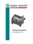
ENGLISH
http://www.rangeservant.com
USER’S MANUAL
BALL DISPENSER
ULTIMA-8
ULTIMA-12
ULTIMA-20
ULTIMA-45
CONTENTS
1
2
3
General information
1.1
Preface
4
1.2
EC Declaration of Conformity
5
1.3
Description
1.3.1
Ball Dispenser
1.3.2
Ball Management System
6
6
6
1.4
Identification
6
1.5
Technical specifications
7
Safety
8
2.1
General
8
2.2
Conformity with mandatory requirements
8
2.3
Remaining risks
8
2.4
Authorised use
9
2.5
Unauthorised use
9
2.6
Emergencies
2.6.1
Fire
10
10
2.7
Operational reliability
10
How to use the Ball Dispenser
11
3.1
4
4
Necessary qualifications
11
3.2
BA-99 Control System
3.2.1
Introduction
3.2.2
Getting started
3.2.3
Adjustment of conveyor belt speed
3.2.4
Adjustment of photocell
11
11
12
12
13
3.3
Payment Methods and Prices
3.3.1
Range Servant® Tokens
3.3.2
Mechanical Coin Contol
3.3.3
Electronic Coin Control Cashflow 340
3.3.4
Manual magnetic card reader (EMC -30)
14
14
15
17
19
Design and function
20
4.1
General
4.1.1
Machine exterior
4.1.2
Machine interior
English
User’s Manual – Ball Dispenser Ultima
20
21
22
-2-
4.2
Description of components
4.2.1
Grid
4.2.2
Payment Methods
5
Maintenance
23
23
23
24
5.1
General
24
5.2
Periodical maintenance
24
5.3
Maintenance intervals and instructions
24
5.4
Troubleshooting and repair
26
5.5
Function test
27
6
Installation
28
6.1
Factory testing and configuration
28
6.2
Installation of the ball dispenser
28
6.3
Installation – Wiring Diagram
6.3.1
Wiring Diagram for the connection of BA-99 to the Ball Dispenser
6.3.2
Wiring of Payment Systems
6.3.3
Cables
7
Spare parts
7.1
31
31
32
36
37
External
37
7.2
Control box
7.2.1
Control box door with mechanical coin control
7.2.2
Control box door with electronic coin control
7.2.3
Inner side of the control box door with mechanical coin control
7.2.4
Inner side of the control box door with electronic coin control
7.2.5
Inside the control box, EMC -30 card reader
38
39
39
40
41
42
7.3
Internal
7.3.1
Grid
43
44
8
Retailers and representatives
45
8.1
Head Office
45
8.2
Your Sales Representative
45
Title:
Prepared by:
Date:
Number of words:
Version:
-3-
br02ultima-e.doc
Johan Carlsson
2002-08-08
6617
64
User’s Manual – Ball Dispenser Ultima
English
1 General information
1.1 Preface
We congratulate you to your new Range Servant machine. You have made a good
choice! Not only have you chosen an excellent state-of-the-art Ball Dispenser with little
demands on maintenance but you have also chosen quality. Quality is ensured with the
help of modern production techniques, carefully chosen materials and the responsible
workmanship of our staff.
This User’s Manual contains all the information necessary to fully understand the
maintenance and operation of the machine.
The machine may be equipped with another a bit more complicated control system
referred to as the Select System, in which case some of the information given herein
does not apply. Please then refer to the separate manual for the Select System.
Study the User’s Guide carefully before using the machine. If these instructions
are not followed, persons using the machine might be injured or the equipment itself be
damaged. In many cases, following the instructions is a necessary condition for Range
Servants’ warranty to be applicable. Every person operating the machine must read
these instructions.
No part of this publication may be reproduced without the written authorisation of Range
Servant.
We now offer a limited three-year warranty on our Ball Dispensers. This does not
include payment systems and normal wear and tear. Study the warranty conditions
carefully and keep them in a safe place. If you have any questions, or if problems should
arise, please contact your Range Servant representative.
THREE-YEARS WARRANTY
Range Servant AB hereby undertakes to provide a warranty on material and function on the
RANGE SERVANT dispenser for three years from the date of delivery. The guarantee does not
cover payment systems and wearing parts. This engagement applies to repaired or replaced
components for a period of three months. This undertaking only applies to the original purchaser.
It also applies only to shortcomings of those parts, which the manufacturer verifies after due
inspection. Repairs or replacement of parts may only be carried out by a representative
authorised by the manufacturer. The manufacturer also guarantees that the equipment delivered
matches the product description supplied. THE UNDERTAKINGS SPECIFIED IN THIS AGREEMENT
CONSTITUTE THE MANUFACTURER’S SOLE OBLIGATION TOWARDS THE PURCHASER. THE
MANUFACTURER IS IN NO WAY RESPONSIBLE FOR ANY UNDERTAKINGS OUTSIDE THE
FRAMEWORK OF THIS WARRANTY CERTIFICATE. Neither is the manufacturer responsible for
any undertakings given by any outside person during the sales negotiations. The warranty
agreement does not apply to equipment that has been repaired or replaced by
persons/companies not authorised by the manufacturer. The manufacturer’s warranty
undertaking does not apply if the equipment is used incorrectly, if it has been damaged through
improper maintenance or accidents or if it has been handled in a way not specified in the manual
which is supplied with the dispenser upon delivery. The manufacturer is also free from financial
liability for any type of injury that may arise in connection with the sale and repair of the equipment
and from injuries to third parties in conjunction with its use.
English
User’s Manual – Ball Dispenser Ultima
-4-
1.2 EC Declaration of Conformity
In accordance with the Machine Directive 89/392/EEC, annex IIA.
The Manufacturer:
Range Servant AB
Skallebackavägen 11
SE- 302 41 HALMSTAD
Sweden
The Representative:
(To be filled out by a representative established within the EU)
..................................................................................................
Company
..................................................................................................
Address
..................................................................................................
Telephone
Declare that:
Ball Dispenser ..........................................................................
Machine
..................................................................................................
Type
..................................................................................................
Serial no., manufacturing no. etc.
A)
is in conformity with Council Directive 89/392/EEC of 14 June 1989 concerning
approximation of the laws of the Member States relating to machines in particular as
referred to in Annexe I to this Directive concerning essential health and safety
requirements in connection with the design and manufacture of machines, as amended
by Council Directive 91/368/EEC of 20 June 1991 on the amendment of Directive
89/392/EEC concerning approximation of the laws of the Member States relating to
machines;
B)
(if applicable)
are manufactured in accordance with the following regulations, directives etc.: ............... ;
C)
that the harmonised standards 292-1, 292-2
and 292-2A (or parts thereof) have been applied
(if the requirements under A have been fulfilled)
D) (if applicable) are manufactured according to the following national standards and
technical specifications:...................................................................................................... .
Halmstad,
...............................................................
Date
Jordan Knez
President
-5-
...............................................................
Signature
User’s Manual – Ball Dispenser Ultima
English
1.3 Description
1.3.1 Ball Dispenser
The Ball Dispenser can be used either as a stand-alone machine or it can be integrated
into a complete, automated system - the Range Servant Ball Management System.
The user-friendly ball dispensers from Range Servant are designed to accept different
types of payment and to deliver, quickly and consistently, the exact number of balls.
Prices are differentiated and several payment methods can be used in parallel. The
number of dispensed balls per payment can be easily changed by the user himself. The
balls are handled with care and only undamaged and clean balls are delivered to the
player.
1.3.2 Ball Management System
Range Servant can deliver a complete, flexible Ball Management System adaptable to
any kind of driving range requirements. The Ball Dispenser can be combined with the
work-efficient, environment friendly Ball Washer. The Ball Washer in turn can be
connected to the Elevator, the Conveyor Belt or the Blower for the transport of clean,
undamaged balls from Washer to Dispenser. The system also includes a Ball Picker
machine picking up used balls from all over the driving range. Thus the circle is closed
and manual work reduced to a minimum.
By applying our extensive know-how to the specific problems of every driving range we
are able to offer tailor-made solutions.
1.4 Identification
When contacting Range Servant, please identify your machine with the help of the
information contained in the identification plate. The identification plate is well visible and
firmly attached and contains the following information:
• Name and address of the manufacturer
• CE-marking
• Designation of series or type of machine
• Serial no., if any
• Year of manufacture
Fig. 1: Product identification plate
English
User’s Manual – Ball Dispenser Ultima
-6-
1.5 Technical specifications
General
Ultima-8
Capacity [balls]
Capacity [balls/h]
Settings [balls/ payment]
8000
30000
1-999
Ultima-12*
Ultima-20*
12000
30000
1-999
Ultima-45*
20000
30000
1-999
43000
30000
1-999
Dimensions:
Height [mm] /([in])
Height open lid [mm] /([in])
Width [mm] /([in])
Depth [mm] /([in])
Weight, with balls [kg]
Weight, without balls [kg]
1330 (52.4) 2056 (80.9 2056 (80.9) 2056 (80.9)
1790 (70.5)
1012 (39.8) 1012 (39.8) 2022 (79.6) 2022 (79.6)
760 (29.9) 760 (29.9) 760 (29.2) 1520 (59.8)
462
648
1112
XX
84
89
173
249
Electric system:
Mains voltage [V, 50/60 Hz]
Control voltage [V, DC]
Effect, feeding motor [W]
230/115
230/115
12 and24 12 and24
17.4
17.4
230/115
12 and24
2x17.4
230/115
12 and24
2x17.4
Operating Conditions:
Operating Temperature [°C] /([°F])
+2 - +50 (+35- +122)
* Ball Washer and elevator are not included
Fig. 2: Ball dispenser Ultima-8.
The level of airborne noise has been measured for an identical machine under normal
operating conditions.
The values indicate the sound pressure level measured 1 m from the sides of the
machine and 1,6 m from the floor or access platform.
Sound pressure at the machine (dB, Lin)
Sound pressure at the machine (dB, A)
XX
XX
XX
XX
XX
XX
XX
XX
The manufacturer reserves the right to alter any details of the products without prior notice.
Patents: EUROPE 99903992.8, AU 2445699, CA 2318910, USA PCT/SE99/00069, CN 99803416.9
-7-
User’s Manual – Ball Dispenser Ultima
English
2 Safety
2.1 General
Safety measures are a combination of measures taken by the manufacturer when
designing and building the machine and measures that have to be taken by the user.
The machine has been designed to function for its intended purpose. It has been
designed and manufactured in such a way that configuration and maintenance can take
place with the least possible risks to the operator, provided such work is carried out
according to the instructions laid down in the User’s Manual.
The objective of the safety measures is to eliminate all accident hazards during the
operational life of the machine which also includes the assembly and dismantling of the
machine, including any hazards arising as a consequence of such abnormal
circumstances as can be anticipated.
Accessories and spare parts that have not been approved by Range Servant can lead
to personal injuries and/or equipment damage and affect the operational reliability of the
machine. For the sake of safety you should therefore exclusively use accessories and
original Range Servant spare parts recommended by Range Servant.
Such accessories and spare parts are specially intended for the machine and are
approved by us with regard to safety.
All Range Servant retailers keep accessories and spare parts at your disposal along
with competent advice. They also have the technical qualifications necessary for
installing your machine and are informed about what technical changes are authorised.
Damage caused by the use of accessories and spare parts not having been approved
by Range Servant and damage due to unauthorised technical modifications are not
covered by the warranty obligation.
2.2 Conformity with mandatory requirements
The Range Servant ball management machines fulfil the personal safety requirements
of the EU Machine Directive 89/392/EEC as amended by Directives 91/368/EEC,
93/44/EEC and 93/68/EEC, with a special reference to Annex I of the Directive
concerning essential health and safety requirements in connection with the design and
manufacture of machines, as amended by Directive 91/368/EEC. Furthermore the
harmonised standards 292-1, 292-2 and 292-2A (or parts thereof) have been applied.
The electrical equipment fulfil the safety provisions laid down in the EU low voltage
directive 73/23/EEC, as amended by directive 93/68/EEC.
2.3 Remaining risks
There are warning signs serving as a reminder and warning to the user of any
remaining risks, i.e. risks that we have not been able to eliminate, or sufficiently
minimise, in our design and against which technical safety measures do not provide
complete, or sufficient, protection. The warning signs shall be written in the local
language and, on request, in the language understood by the respective operator. The
signs are yellow with black characters. They are big enough to be readable from a
distance of three meters.
English
User’s Manual – Ball Dispenser Ultima
-8-
Fig. 3: Warning signs on front hatch
• Always disconnect the power supply to the machine before carrying out maintenance
or service work. The mains switch is located in the control box in the lower right hand
corner of the printed circuit board.
DANGER!
Don’t touch
Risk of electric shock
Fig. 4: Warning signs in control box
• Never touch the circuit board or other electrical components in the control box. They
can be current conducting and cause injury to person and/or equipment damage
• Mechanical or electrical alterations may only be undertaken in consultation with
Range Servant.
2.4 Authorised use
The ball-dispensing machine may only be used for the distribution of golf balls. For the
machine to operate properly, the balls must be clean and undamaged or else they may
get stuck and cause machine failure.
Distribution of balls may only start provided the machine has been installed according to
the instructions contained in this Manual.
2.5 Unauthorised use
Using accessories or spare parts not recommended by Range Servant might cause
personal injury and/or equipment damage and affect the operational reliability of your
ball dispenser. For safety reasons, use only those components recommended by us.
They are intended for your machine, they have been chosen for safety reasons and they
are approved by the manufacturer.
Damage caused by the use of accessories and spare parts not having been approved
by Range Servant or damage due to unauthorised technical changes are not covered
by the warranty obligation.
-9-
User’s Manual – Ball Dispenser Ultima
English
2.6 Emergencies
2.6.1 Fire
Water shall be used as an extinguisher in the event of fire, except if the fire is located in
the electric equipment, where a carbon dioxide extinguisher must be used.
2.7 Operational reliability
For trouble-free operation and long service life the instructions below should be
followed:
• Place the ball-dispensing machine on a firm and level surface.
• Place the machine under cover so that only the front is accessible to members of
the public. If the machine is card-operated it must stand under cover for the warranty
to apply.
• Never strain the machine by loading it with more balls than recommended. The
loading capacity for your machine is stated in the Technical Specifications at the end
of the Manual.
• The machine should be connected to its own wall socket to prevent interference with
its electronic system.
• Make sure that the electric box is always properly shut and covered when rinsing the
machine. Moisture and water can damage the electrical components.
• When cleaning inside the dispenser never spray water directly onto the electric
motor.
English
User’s Manual – Ball Dispenser Ultima
- 10 -
3 How to use the Ball Dispenser
3.1 Necessary qualifications
Due to the complex design and operation of the machine the person carrying out
service and maintenance work must have the necessary qualifications. He is required
to have attended a training course, in the form of a comprehensive study of the User’s
Manual, followed by a written statement to the fact that he has well understood its
contents.
If the person has to be absent from work for more than three months, training has to be
repeated.
3.2 BA-99 Control System
LO
x 100 x 10
HI
x 1
1
2
3
G
IN
+
+12V
RXD
TXD
GND
G
P1
G
P2
G
P3
G
+
R
D
+
RESET
ON
230
115
+
B
FUSE
I
ON
WATER
FUSE
OFF
DL DN DL DN IL IN SL SN
0
L
N
Fig. 5: BA-99 Control System
3.2.1 Introduction
The BA-99 system has three payment channels marked P1-P3 allowing the user to
choose between three different amounts of balls to be dispensed ranging from 1-999.
The desired amount is selected with the help of the nine knobs located to the left of the
terminal block G – P1-P3. More details are given in the following chapter “Getting
started”.
Payments can also be made during the dispensing process and will then be
accumulated. A green LED marked ON is lit to indicate that power is on and a red LED
marked DEP to indicate that payment has been registered and that the machine is
- 11 -
User’s Manual – Ball Dispenser Ultima
English
prepared to dispense balls. The system is also equipped with a small circuit card
consisting of two LED’s , a green and a red one, giving continuous information to the
user. Green LED indicates that mains supply is on and red that payment has been
made and that machine is in the process of dispensing.
3.2.2 Getting started
You can decide yourself how many balls you wish the machine to dispense per
payment. The Ball dispenser accepts different payment methods and you are free to
decide whether the machine shall make the same number of turns for all the different
payments methods or not.
Connect the Ball Dispenser to the 230 VAC mains supply.
Adjust the ball dispensing knobs for the respective payment channel according to wish.
Make your payment and check that the correct number of balls are dispensed. The
machine dispenses balls at two different speeds – low and high. Dispensing starts at
low speed, which allows for the conveyor belt to start running, and then continues at
high speed. When there are only five balls left, the speed is again reduced to allow for
the conveyor motor to stop at the right point preventing too many balls to be delivered. If
you wish to adjust the speed of the conveyor belt, see the following chapter “Adjustment
of conveyor belt speed”.
Example:
Payment channel 1
23 Balls
x 100 = 0
x 10 = 2
x 1=3
x 100 x 10
x 1
1
2
3
Payment channel 2
54 Balls
x 100 = 0
x 10 = 5
x 1=4
Payment channel 3
128 Balls
x 100 = 1
x 10 = 2
x 1=8
3.2.3 Adjustment of conveyor belt speed
The control card BA-99 is equipped with two knobs for adjustment marked HI and LOW
as well as with two micro-switches that are located on the upper left side of the card.
Press the micro-switch corresponding to either adjustment knob HI or LOW; the
conveyor belt starts moving. Use a small screw driver to adjust the speed. LOW
regulates the starting speed and the dispensing speed for the last five balls. HI regulates
the normal dispensing speed.
The LED marked STB on the photocell located above the conveyor belt shall be burning
with steady light and the LED marked OP.L shall blink with each detected ball.
English
User’s Manual – Ball Dispenser Ultima
- 12 -
3.2.4 Adjustment of photocell
The photocell is the component detecting the balls and signalling to the control system
that the correct number of balls have been dispensed.
The photocell sends a red signal indicating where the balls are detected.
The photocell is adjusted as follows:
• Place a ball on the highest point of the conveyor belt. Make sure it is in line with the
photocell and that the red ray of light from the photocell hits the ball at a point about
2/3 of the height of the ball.
• Move the ball sideways, all the while checking that the two LED’s – STB and OP.L of the photocell burn with steady light.
• Start dispensing and check that OP.L blinks with each detected ball.
STB = Stability LED means that the reflecting light is sufficient for detection.
OB.L = Operating LED means detection of an object.
- 13 -
User’s Manual – Ball Dispenser Ultima
English
3.3 Payment Methods and Prices
The Ball Dispenser is equipped with an operating panel where the customer can select
the desired payment method. The panel contains two LED’s, openings for coins or
tokens, and a slot for magnetic cards or bill scanner.
3.3.1 Range Servant® Tokens
Range Servant® has 16 different types of tokens for use in the Range Servant®
mechanical token acceptor.
Token types: RS- I to RS-IX, RS-A to RS-H
There are also two types of tokens for use in electronic coin acceptors.
Token types: RS-90, RS-91
RANGE
RANGE
RANGE
SERVANT
SERVANT
SERVANT
RS-A
RS-B
RS-C
RANGE
RANGE
RANGE
SERVANT
SERVANT
SERVANT
RS-D
RS-E
RS-F
RANGE
RANGE
SERVANT
SERVANT
RS-G
RS-H
RS-I
RS-II
RS-III
RS-IV
English
User’s Manual – Ball Dispenser Ultima
- 14 -
RS-V
RS-VII
RS-90
RS-91
RS-VIII
RS-IX
3.3.2 Mechanical Coin Contol
Mechanical Coin control for one or two coins.
When a two coin control has been installed, this also includes a so called adding circuit
card.
This card allows for prices that are higher than the coin value.
switch
Figure 7: DIP switches
The adding circuit card (no. 107810) contains two 8position DIP-switches marked DIP 1 and DIP 2 and
two cable contacts.
The internal relation between the coins is set with the
help of the DIP1 (switches 1-4).
The coin with the lowest value is always given value 1.
The next setting determines how many times coin 2 is
bigger than coin 1.
1-2 relation
(switch 2 ON)
1-5 relation
(switch 1+3 ON)
1-10 relation
(switch. 2+4 ON)
Relay output port (1 sec. impulse output) DIP 1 switch
7+ 8 ON.
Figure 6: Meachanical coin control
- 15 -
User’s Manual – Ball Dispenser Ultima
English
The price is set and modified by changing the position of the switches on DIP 2. The
value is binary which means that:
Switch
1 represents
1 x the smallest coin
2 represents
2 x the smallest coin
3 represents
4 x the smallest coin
4 represents
8 x the smallest coin
5 represents 16 x the smallest coin
6 represents 32 x the smallest coin
7 represents 64 x the smallest coin
8 represents 128 x the smallest coin
The switches can be variously combined to obtain prices ranging from the biggest to
the smallest coin.
Example 1:
The smallest coin is 5 SEK and the biggest 10 SEK.
You wish to obtain a price of 25 SEK.
Set switch 1 (=5 SEK) and 3 (=20 SEK) in the ON position.
5+0+20+0=25
Example 2:
The smallest coin is 5 SEK and the biggest 10 SEK.
You wish to obtain a price of 10 SEK.
Set switch 2 (=10 SEK) in the ON position.
0+10+0+0=10
English
User’s Manual – Ball Dispenser Ultima
- 16 -
3.3.3 Electronic Coin Control Cashflow 340
The electronic coin control can be programmed for up to twelve different types of coins
or ten coins plus the two electronic tokens RS-90 and RS-91.
(In use from 970801 Mars® model Cashflow 340)
switch
Figur 9: Dipomkopplare
The electronic coin control is equipped with a
4-position DIP-switch that used to set prices
and to block/allow coins.
Figure 8: Electronic Coin Control Cashflow 340
3.3.3.1 Change of prices, blocking of coins etc... Cashflow 340.
The following instructions describe how to modify prices, block coins etc.
1. Cut the power supply to the coin control.
2. Dismount the coin control from its holder and remove the interface protection by
pulling it downwards. Re-mount the coin control in its holder.
3. Switch on the power supply to the coin control.
4. Adjust the position of the switches according to the respective function.
If the switches are already in the correct position, then do the following:
• Change the position of one switch.
• Switch off the power supply and switch it on again.
• Re-set the switch in the correct position and press the coin return button.
5. Carry out the desired function.
6. Again cut the power supply to the coin control and re-mount the interface protection.
7. Switch on the power supply.
Blocking a coin
- 17 -
User’s Manual – Ball Dispenser Ultima
English
1. Position the switches 1-4 as shown in
the diagram.
2. Press the coin return button once.
3. Insert the coin you wish to block and check that it is blocked.
4. Press the coin return button once.
5. Check that the setting has been carried out.
Allowing a coin
6. Position the switches 1-4 as shown in
the diagram.
7. Press the coin return button once.
8. Insert the coin you wish to allow and check that it is accepted.
9. Press the coin return button once.
10. Check that the setting has been carried out.
Changing the price
1. Position the switches 1-4 as shown in
the diagram.
2. Press the coin return button once.
3. Insert the coin you wish the price to be
and check that is is accepted.
4. Press the coin return button once.
5. Check that the setting has been carried out.
.
Test the coin output port
1. Position the switches as shown in the
diagram.
2. Press the coin return button.
3. Check that the machine starts dispensing.
English
User’s Manual – Ball Dispenser Ultima
- 18 -
3.3.4 Manual magnetic card reader (EMC-30)
This is done by sliding a magnetic card through a card reader. The cards can be
programmed to dispense anything between 1 and 30 baskets.
The card reader is equipped with a two digit display showing the number of dispenses
left on the card.
You will find the wiring diagram for Magnetic card reader EMC -30 in paragraph 6.3.2.5
“Magnetic car reader EMC -30”.
Slide the card downwards through the scanner with
the dark magnetic strip held away from you and
facing left. The figure which appears in the display
shows the number of baskets (including this one!)
that you can fill from the machine.
If you only want to know how many baskets you
have left, press in the knob on the left of the scanner
while sliding the card through. This does not reduce
the number of baskets left, as no balls will be
dispensed.
Keep the card safe. Do not bend it, and keep it away
from strong magnetic fields.
Figure 10: EMC-30
- 19 -
User’s Manual – Ball Dispenser Ultima
English
4 Design and function
4.1 General
The machine is intended for use as a golf ball dispenser. It consists of a ball magazine
and is inside fitted with two plates on two levels for load reduction and, at the bottom, a
grid.
The grid consists of a number of ball ducts, arranged next to each other and ending
above a conveyor belt transporting the balls to the ball chute.
A photocell is installed in connection with the conveyor belt counting the balls being
transported by the belt.
All interior surfaces are inclined so that the balls are continuously flushed downwards.
The lower level allows for damaged balls and debris to be sorted out.
All essential parts of the Ball Dispenser are manufactured of stainless steel, rust
protected steel or aluminium.
The Range Servant Boll Dispenser has been designed in order to provide driving range
owners with a long-lasting, reliable, practical and economic golf ball management
system.
English
User’s Manual – Ball Dispenser Ultima
- 20 -
4.1.1 Machine exterior
Fig. 11: Outside front view
Pos.
1
2
3
4
5
6
7
8
9
10
11
- 21 -
Designation
Control box door
Locks for control box, front hatch and lid
Shackle, front hatch lock and lid
Shackle, control box door
Lower front panel
Front inspection hatch
Ball shute
Upper front panel
Front portion of lid
Lid hinges
Rear portion of lid
User’s Manual – Ball Dispenser Ultima
English
4.1.2 Machine interior
Fig. 12: Inside of the ball dispenser, side view
Pos.
1
2
3
4
5
6
7
8
9
10
English
Designation
Upper inclined plate
Lower inclined plate
Left side plate of grid
Right side plate of grid
Shock absorber
Vibrator motor
Photocell DLS 10 R NPN
Dispenser motor
Control box
Grid
User’s Manual – Ball Dispenser Ultima
- 22 -
4.2 Description of components
4.2.1 Grid
The lowest level inside the ball dispenser consists of a grid. On top of the grid is a
movable plate. At one end of the movable plate is a funnel-shaped ball duct discharging
onto a conveyor belt divided into compartments. The conveyor belt runs between a
lower and upper pulley. The angle of the conveyor belt is designed so that the balls
automatically roll on from one compartment to the other until all compartments are filled
with balls. An electric conveyor motor runs the upper pulley and thus the conveyor belt.
The conveyor motor is connected to an electronic control circuit including a photocell
located next to the conveyor belt counting the balls passing on the belt.
4.2.2 Payment Methods
The ball dispenser can be operated with tokens, coins or magnetic cards. Each
machine can run more than one payment system at the same time, for example
combining token/coin or token/coin/card. The number of balls dispensed need not
necessarily be the same for the different forms of payment (see the examples, chapter
3.3.2).
Below you can read how to alter the price on the coin mechanism, both for manual
operation and the electronic system.
The price per unit when using a card mechanism is determined by the price of the card
and your choice of the number of balls dispensed per card. The cards can be
programmed to dispense anything between 1 and 30 baskets. You can programme the
card yourself using the magnetic card programmer OBL-E, see fig. 13. or you can ask
Range Servant to do it for you.
Figure 13: OBL-E
- 23 -
User’s Manual – Ball Dispenser Ultima
English
5 Maintenance
5.1 General
Range Servant will provide accessories and original spare parts together with
competent advice.
Maintenance carried out correctly minimises defects and ensures maximum service life
and reliable operation. Any malfunctions are detected at an early stage and are
therefore easily corrected. Regular maintenance minimises defects and equipment
breakdown.
The following maintenance instructions only refer to the most common problems and
their causes.
5.2 Periodical maintenance
5.3 Maintenance intervals and instructions
Maintenance intervals:
1. After 300 operating hours
2. Once every month
3. Once every golf season
Maintenance intervals and instructions
1
1.1
1.2
2
2.1
2.2
2.3
2.4
2.5
2.6
1
Machine exterior
Lubricate the eccentric lock, the lid and front hatch locks and
the hinges of lid and front hatch with ordinary lubricating oil.
Lubricate the eccentric lock, the lid and front hatch locks and
the hinges of lid and front hatch with ordinary lubricating oil.
Machine interior:
Tighten the fixation bolts of the grid.
Tighten the fixation bolts of the vibrator motor.
Lubricate the linking arms with ordinary lubricating oil.
Wipe the photocell that counts the balls. The photocell is
located above the conveyor belt. Use a piece of cloth
moistened with pure alcohol.
If chemical fertilisers are used on the driving range, we
recommend that the dispenser is cleaned thoroughly once a
month to prevent corrosion of the machine’s internal
components. Cut the power supply to the machine, open the
front hatch, remove grass and other debris and rinse with
clean water.
Empty the machine, sort out worn or damaged balls, stones
and grit etc and clean the inside with normal clean water. (Do
not spray water directly onto the electric motor.)
English
User’s Manual – Ball Dispenser Ultima
2
3
X
X
X
X
X
X
X
X
- 24 -
2.7
2.8
Clean and dry the ball duct (located after the grid).
Clean and dry the conveyor belt.
3
3.1
Electronic components:
If the machine is fitted with a magnetic card reader EMC -30 the
reader head has to be cleaned. Moisten a piece of cloth with
methylated spirit, wind it round the card and slide the card
through the reader 5-10 times.
- 25 -
User’s Manual – Ball Dispenser Ultima
X
X
X
English
5.4 Troubleshooting and repair
Although the operation of the machine is most reliable, problems may arise for various
reasons.
Attention!
To reduce the time spent on troubleshooting, always start by checking that
cables and connections are clean and tightened.
SYMTOMS
POSSIBLE DEFECT
CORRECTIVE MEASURES
The power supply is not
connected.
Connect the machine to the
power supply.
The ON/OFF switch on the
circuit card is not "ON"
Set the switch in the "ON"
position.
Defective fuse(s) on the circuit
card.
Replace the fuse(s)
(2.5A/250V).
Payment method defect.
Check the voltage with
Ohmmeter. The voltage shall
fall from 5VDC to 0VDC when
active. All payment methods
must be NO (Normally Open).
The Ball dispenser
does not start.
One payment channel is
active..
Measure the payment channel
voltage and check that no
channel is 0VDC.
The Ball Dispenser
delivers too many
balls.
The photocell is not correctly
adjusted.
Adjust the photocell according
to instructions (paragraph
3.2.4 "Adjustment of photocell"
The Ball dispenser
delivers too few balls.
The conveyor belt speed is not
correctly adjusted.
Adjust the speed according to
instructions (paragraph 3.2.3
"Adjustment of conveyor belt
speed".
Fig. 14: Troubleshooting for RS-Ultima 8, 12, 20, 45.
English
User’s Manual – Ball Dispenser Ultima
- 26 -
SYMTOMS
POSSIBLE DEFECT
Token contacts do not close.
CORRECTIVE MEASURES
Check the voltage with
Ohmmeter. The voltage should
fall from 5VDC to 0VDC when
active (=closed position). The
token switch must be
connected in the NO position
(Normally Open).
Check that the token cable is
not damaged or has stuck.
The (Mechanical) Coin Control
switch does not close.
See above for token switch.
The coin output of Electronic
Coin Control Cashflow 340 is
not activated.
Activate coin output of
Cashflow (acc. to 3.3.3.1
"Change of price, blocking of
coins etc.").
Measure payment channel
with Ohmmeter. Voltage
should fall from 5VDC to 0VDC
when active. Check the price
setting.
The Ball Dispenser
does not start.
The magnetic card reader
EMC-30 activity does not
appear in the display.
EMC-30 purchase indications
appear on the display but the
displayed number does not
change and dispensing does
not start.
There are no dispenses left on
the card. Try a new card.
Check that resistor 33k Ohm is
not defective.
Check that the mechanical
switch of the reader unit is not
closed.
Figure 15 Troubleshooting for payment methods.
5.5 Function test
After maintenance or repair work the operation of the machine should be tested by
running the machine with the front hatch open. Insert a coin/token or payment card and
check that everything works to satisfaction.
- 27 -
User’s Manual – Ball Dispenser Ultima
English
6 Installation
6.1 Factory testing and configuration
The ball dispensers are always tested and configured before delivery to the customer.
On this occasion all the parameters of the control system are adjusted according the
customer’s wishes.
Our objective when carrying out this final check is to verify that the product corresponds
on all accounts to the requirements laid down by the customer when ordering and to
prevent defective products from being brought onto the market.
6.2 Installation of the ball dispenser
For trouble free operation, place the ball dispenser on a firm and level surface.
We recommend that the machine be located under cover and that only the front of the
machine be accessible to members of the public. If the machine is card-operated, it
must stand under cover according to the terms of the warranty.
Remove the keys tied into the
opening for the ball shute in the
front hatch.
The keys are identical and are
used for opening the control box
(see arrow).
Fig. 16: Location of keys on delivery
English
User’s Manual – Ball Dispenser Ultima
- 28 -
Inside the control box there are
another four keys, all identical,
which fit the lid of the ball
dispenser
and
the
front
inspection hatch.
Fig. 17: Location of keys in control box
Open the lid of the ball dispenser
and remove the package
containing a plastic tray, a ball
chute, the number of tokens
ordered for the machine and
other accessories, if any.
Place the plastic tray inside the
control box so that the tokens fall
directly into the tray. If the
machine is both coin and token
operated, there will be two trays
for sorting both forms of
payment at source.
Fig. 18: Location of plastic collecting tray
Screw the ball chute into place
over the hole in the front hatch.
Fig. 19: Mounting of ball chute
- 29 -
User’s Manual – Ball Dispenser Ultima
English
The electric cable is located in
the bottom of the machine and is
pulled out through the hole
situated on the side or in the
bottom of the machine.
IMPORTANT! Do not connect
the cable until the machine is
ready for operation.
Fig. 20: Location of the electric cables
English
User’s Manual – Ball Dispenser Ultima
- 30 -
6.3 Installation – Wiring Diagram
To ensure safe and reliable operation, the control system must be correctly installed
and grounded (earthed) and provided with good immunity against electronic noise.
6.3.1 Wiring Diagram for the connection of BA-99 to the Ball Dispenser
LO
HI
x 100 x 10
x 1
1
2
3
low speed adjustment
G
P1
G
P2
G
P3
G
+
high speed adjustment
C: Supply voltage photocell OVDC (BLUE)
G
IN: Signal from photocell (BLACK)
IN
+
+: Supply voltage phtocell 12VDC (BROWN)
R
D
+
+12V
+
P-1 DISPGND +
P-1 GNDGND
RXD
TXD
GND
RESET ON
Cable colours are indicated by (COLOUR)
R, D, + are the contacts for the LED’s mounted in the door
R: Supply voltage 230VAC is ON, green LED (GREEN)
D: Dispensing in progress, redLED (BROWN)
+: Supply voltage 12VDC to the LED’s (YELLOW)
230
115
+: Supply voltage conveyor motor 12 VDC (RED)
-: Supply voltage conveyor motor 0 VDC (BLACK)
+
B
Legend: LED’s
FUSE
ON: Supply voltage 230VAC is ON
WATER
0
FUSE
OFF
DL DN DL DN IL
RESET: Zeroing of microprocessor
I
ON
IN SL SN
DL: Vibrator motor 230 VAC (BROWN)
DN: Vibrator motor 230 VAC (BLUE)
L
N
L: Supply voltage 230VAC (BROWN)
N: Supply voltage 230VAC (BLUE)
Figure 21: Wiring diagram for the connection of Ball Dispensers model RS-Ultima 8/12/20/45.
- 31 -
User’s Manual – Ball Dispenser Ultima
English
6.3.2 Wiring of Payment Systems
6.3.2.1 Token Control
LO
x 100 x 10 x 1
HI
1
2
3
G
P1
G
P2
G
P3
G
+
R
D
+
G
+12V
RXD
TXD
GND
IN
+
WHITE
BROWN
RESET ON
230
115
+
B
FUSE
I
ON
WATER
0
FUSE
OFF
DL DN DL DN IL IN SL SN
L
N
Figure 22:Wiring of Range Servant Token Control.
The token control micro switch is to be installed in the NO position - Normally Open.
English
User’s Manual – Ball Dispenser Ultima
- 32 -
6.3.2.2 Mechanical Coin Control
The mechanical coin control is wired according to the same wiring diagram as the
token control (see above “Token”)
LO
HI
x 100 x 10
x 1
1
2
3
G
P1
G
P2
G
WHITE
BROWN
P3
G
+
G
IN
+
+12V
RXD
TXD
GND
R
D
+
RESET O N
230
115
+
B
FUSE
I
ON
WATER
0
FUSE
OFF
D L D N D L D N IL IN SL SN
L
N
Figure 23 Wiring of the one coin mechanical coin control
6.3.2.3 Mechanical Coin Control with “adding” printed circuit card
x 100
LO HI
x 10
x 1
1
2
3
G
P1
G
P2
G
P3
G
+
black
black
ON
black
black
ON
2
1 345678
2
78
1 3456
DP2
DP1
R
G
IN
+
D
+
+12V
RXD
TXD
GND
RESET
ON
P1
+ -
C NONC
P2
black
black
black
black
black
230
115
+
B
FUSE
I
ON
WATER
FUSE
OFF
DL DN DL DN IL IN SL SN
0
L
N
Figure 24 Wiring of 2-coin+adding printed circuit card.
- 33 -
User’s Manual – Ball Dispenser Ultima
English
6.3.2.4 Electronic Coin Control (Mars® Cashflow 340)
LO
HI
x 100 x 10
x 1
1
2
3
G
IN
+
G
P1
G
P2
G
P3
G
+
green
braun
white
yellow
R
D
+
+12V
RXD
TXD
GND
RESET
ON
230
115
+
B
FUSE
I
ON
WATER
FUSE
OFF
DL DN DL DN IL
IN SL SN
0
L
N
Figure 25: Wiring of the Coin Control Mars® Cashflow 340.
The electronic coin monitor Cashflow 340 is a totaliser, programmed to send a signal
causing the ball dispenser control system to start dispensing when the internal pre-set
price has been reached. Twelve different types of coins/tokens can be programmed.
English
User’s Manual – Ball Dispenser Ultima
- 34 -
6.3.2.5
LO
Magnetic Card Reader EMC-30
x 100 x 10
HI
x1
1
2
3
G
P1
G
P2
white
braun
G
P3
G
B
C
NC
NO
GND
0V
230V
+
R
D
+
G
+12V
RXD
TXD
IN
+
GND
RESET ON
30
230
115
+
B
FUSE
yellow/green
I
ON
WATER
FUSE
OFF
DL DN DL DN IL IN S L SN
0
L
N
blue
black
brown
Figure 26: Wiring of the card reader EMC-30.
The Card Reader uses pre-programmed magnetic cards that can be programmed for
up to 30 purchases.
The magnetic cards will be programmed by Range Servant.
- 35 -
User’s Manual – Ball Dispenser Ultima
English
6.3.2.5 Counter
LO
x 100 x 10
HI
x 1
1
2
3
12345678
0V
12345678
G
P1
G
P2
G
P3
G
+
0V
COUNT
20HZ
RESET
ENABLE
COUNT
2KHZ
EXT.
RESET
WHITE
BROWN
Counts the number of balls that are dispensed
G
IN
+
RESET
0V
RESET
ENABLE
COUNT
2KHZ
EXT.
RESET
R
D
+
+12V
RXD
TXD
GND
0V
COUNT
20HZ
Counts the number of payments
on payment channel P1
ON
12345678
0V
0V
COUNT
20HZ
RESET
ENABLE
COUNT
2KHZ
EXT.
RESET
230
115
WHITE
BROWN
+
B
FUSE
I
ON
WATER
0
FUSE
Counts the total amount of dispenses
OFF
DL DN DL DN IL IN SL SN
L
N
Figure 27 Wiring of counter.
6.3.3 Cables
ATTENTION! No cables may be exchanged without the prior consent of Range Servant.
6.3.3.1 Cable Specifications
Unit
Mains supply
Motor (Vibrator)
Motor (Dispenser)
Photocell
Cable Type
RKK 3x0.75mm2
RKK 3x0.75 mm2
RKK 2x1mm2
LIYY 4x0.22mm2
6.3.3.2 Power supply
All machines can be supplied with 230/115 VAC +/- 10% 50-60Hz.
English
User’s Manual – Ball Dispenser Ultima
- 36 -
7 Spare parts
In this chapter you will find detailed drawings of the ball dispenser showing the location
of the different spare parts. The tables accompanying the drawings contain information
about spare parts number and designation and the quantity of each spare part installed
per machine model.
( )= Optional accessories are marked with a parenthesis around the digit representing
quantity.
- = The alternative marked with ”-” depends on the customer’s choice of equipment.
7.1 External
Fig. 28: Front view
Pos. Part No.
1
2
101900
3
4
5
6
7
8
9
10
11
101950
101960
DJM 1504
DJM 1505
102000
DJM 1503
106610
106550
106500
- 37 -
Designation
Control box door
Lock for control box, front
inspection hatch and lid
Shackle, front hatch lock and lid
Shackle, control box door
Lower front panel
Front inspection hatch
Ball shute
Upper front panel
Front portion of lid
Lid hinges
Rear portion of lid
Ultima-8
Ultima-12
Ultima20
Ultima45
1
1
1
1
2
2
2
2
1
1
1
1
1
1
1
1
1
1
1
1
1
1
1
1
1
1
2
2
2
2
2
2
1
2
-
2
2
2
2
2
2
1
2
-
User’s Manual – Ball Dispenser Ultima
English
7.2 Control box
Fig. 29: Control box
Pos. Part. No.
1
1
2
3
4
5
6
7
8
9
109410
109400
108600
101920
930125
101900
101960
-
Designation
Token collecting tray, small
Token collecting tray, large
Token monitor
Spare keys
Printed circuit board BA-99
Coin monitor
Token slot
Lock
Shackle, control box door
Control box door
Ultima-8/12
Ultima20/45*
1
(1)
1
1
1
1
1
1
(1)
1
1
1
1
1
() Optional equipment is within brackets
English
User’s Manual – Ball Dispenser Ultima
- 38 -
Fig. 30: Control box, token, magnetic card reader and mechanical coin control
7.2.1 Control box door with mechanical coin control
Pos.
1
2
3
4
Part No.
OKA0000
101900
108000
Designation
Mechanical coin control
Lock
Token slot for the type of token used
Magnetic card reader EMC -30
Ultima-8/12 Ultima-20/45*
(1)
(1)
1
1
1
1
(1)
(1)
() Optional equipment is within brackets
* quantity per side
Figure 31: Control box, token, magnetic card reader and electronic coin control
7.2.2 Control box door with electronic coin control
Pos.
1
2
3
4
Part No.
107900
101900
108000
Designation
Electronic coin control
Lock
Token slot for the type of token used
Magnetic card reader EMC -30
Ultima-8/12 Ultima-20/45*
(1)
(1)
1
1
1
1
(1)
(1)
() Optional equipment is within brackets
* refers to quantity per side
- 39 -
User’s Manual – Ball Dispenser Ultima
English
Figure 32: Inner side of the control box door with mechanical coin control
7.2.3 Inner side of the control box door with mechanical coin control
Pos.
1
2
3
4
5
6
7
7
8
Part no.
10 1900
Designation
Complete lock
10 7800
Circuit card 1/5, 2 coin mechanism
10 7810
10 7310
10 7320
10 7720
10 7700
10 7710
930295
Circuit card 1/2, 2 coin mechanism
Opening for token and 1 coin
Opening for token and 2 coin
Micro switches
Coin control, 1 coin
Coin control, 2 coin
Circuit card with LED -99
Ultima-8/12 Ultima-20/45*
(1)
(1)
(1)
(1)
(1)
(1)
(1)
(1)
(1)
(1)
(1)
(1)
(1)
(1)
(1)
(1)
1
1
() Optional equipment is within brackets
* refers to quantity per side
English
User’s Manual – Ball Dispenser Ultima
- 40 -
Figure 33: Inner side of the control box door with electronic coin control
7.2.4 Inner side of the control box door with electronic coin control
Pos.
1
2
3
4
5
Part no.
10 1900
Designation
Complete lock
10 7800
Circuit card 1/5, 2 coin mechanism
10 7810
107901
930295
Circuit card 1/2, 2 coin mechanism
Electronic coin control, Cashflow 340
Circuit card with LED’s, LED-99
Ultima-8/12 Ultima-20/45*
1
1
(1)
(1)
(1)
(1)
(1)
(1)
1
1
() Optional equipment is within brackets
* refers to quantity per side
- 41 -
User’s Manual – Ball Dispenser Ultima
English
Figure 34: Inside of control box, EMC-30 card reader
7.2.5 Inside the control box, EMC-30 card reader
Pos.
1
2
3
4
5
6
7
8
Part no.
01 5020
10 8000
93 0235
10 9310
10 9500
10 8880
10 8900
10 8600
Designation
Screws
Card reader
Circuit card BA-99
Fuse (2,5A250V)
Cable duct
Micro switch holder
Complete micro switch
Token mechanism
Ultima-8/12 Ultima-20/45*
(2)
(2)
(1)
(1)
(1)
(1)
(2)
(2)
(1)
(1)
(1)
(1)
(1)
(1)
(1)
(1)
() Optional equipment is within brackets
* refers to quantity per side
English
User’s Manual – Ball Dispenser Ultima
- 42 -
7.3 Internal
Figure 35: Cross section
Pos. Part no.
1
2
3
4
5
6
7
8
9
- 43 -
182600
182700
DJM0033
DJM0034
DJA0004
DJM0057
930218
DJA0003
-
Designation
Upper inclined plate
Lower inclined plate
Left side plate of grid
Right side plate of grid
Shock absorber
Linking arm
Photocell, counter
Motor
Control box
Ultima-8
Ultima-12
Ultima20
Ultima45
1
1
1
1
1
1
1
1
1
1
1
1
1
1
1
1
1
1
2
2
2
2
2
2
2
2
2
2
2
2
2
2
2
2
2
2
User’s Manual – Ball Dispenser Ultima
English
7.3.1 Grid
Figure 36: View of the grid through the open front hatch
Pos. Part no.
1
2
3
4
5
6
7
DJM0022
DJM0054
DJM0055
DJA0002
DJA0003
DJM0028
DJM0048
English
Designation
Ball stop plate
Axle for conveyor belt pulley
Clamp screw
Conveyor belt
Conveyor motor
Ball chute
Conveyor belt pulley
Ultima-8
Ultima-12
Ultima20
Ultima45
1
1
2
1
1
1
1
1
1
2
1
1
1
1
2
2
4
2
2
2
2
2
2
4
2
2
2
2
User’s Manual – Ball Dispenser Ultima
- 44 -
8 Retailers and representatives
The following list contains all the necessary information concerning the Range Servant
representative closest to where you live.
The list is continuously updated on our home page http://www.rangeservant.com
8.1 Head Office
Sweden
Range Servant AB
Skallebackavägen 11
302 41 HALMSTAD
Telephone:
+46 35 10 92 40
Fax:
+46 35 10 82 20
E-Mail: [email protected]
8.2 Your Sales Representative
- 45 -
User’s Manual – Ball Dispenser Ultima
English