1
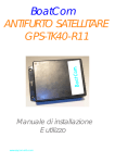
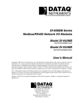
User Manual Rev1.0_ENG INDEX PRECAUTIONS 3 Phone number to receive of credit 32 SAFETY INFORMATIONS 3 Language 33 DECLARATION OF CONFORMITY 4 Audio profile 34 ASSISTANCE & CONTACTS 4 Speaker volume 35 1. INTRODUTION 5 Microphone gain 36 1.1 Description 5 Signal quality 37 1.2 Specifications 5 Relay 1 activation 38 1.3 Connections 6 Relay 2 activation 39 7 Delay relay 1 40 1.4 Models & accessories 9 Delay relay 2 41 2.1 Insert sim card 9 Info single command 42 2.2 External antenna connection 9 Info total command 43 10 Rec camera 44 10 Rec list 45 Rec required 46 2. INSTALLATION 2.3 Power supply 2.4 First start 3. CONFIGURATIONS 3.1 11 11 4. LOG FIRMWARE VERSION 47 Switch A 12 5. TROUBLESHOOTING 48 Switch B 13 6. WARRANTY 49 Switch C 14 7. ASSISTANCE REQUEST FORM 51 Switch D 15 Switch E 16 Switch F 17 Loop call 18 Timeout call 19 Ring tone 20 Advanced switch function 21 Timeout between call 22 Introduction of controls Lock switch 23 Test switch 24 Delete single phone number 25 Delete all phone numbers 26 Password 27 Primary call 28 Manual request of credit 29 Network selection of credit 30 Automatic send sms of credit 31 Reproduction of any part of this manual, in any form without the express written consent of Global Technologies srl. The contents of this manual may be changed without notice. Every care has been taken in collecting and verifying the documentation contained in this manual, however, the Global Technologies srl does not assume responsibility for its use. All other brands, products and trademarks are property of their respective owners. PRECAUTIONS In order to safeguard the safety, security and the functioning of the operator, the following rules must be followed for installation. The system, including cables, in an area without or away from: Dust, moisture, extreme heat and direct exposure to sunlight. Objects that radiate heat. These may cause damage to the container or other problems. Objects that produce a strong electromagnetic field (Hi-Fi speakers, etc.). Liquids or corrosive chemicals. ENVIRONMENTAL CONDITIONS Ambient temperature –15°C to +55°C Product cleaning Use a soft dry cloth without the use of solvents. Vibration or shock Relative umidity from 20 to 80% Be careful not to cause vibration or shock. SAFETY INFORMATIONS Read the directions and instructions in this manual before turning on the device. Breaking the rules may be illegal and could create a hazard. The company assumes no liability if the customer does not observe the following rules. For each of the situations you need to refer to the provisions and rules. This device is a low-power radio transceiver. When activated, it sends and receives radio frequency energy (RF). The device produces magnetic fields, for this reason must be kept away from magnetic media such as diskettes, tapes, etc.. The operation of the device near electrical and electronic devices such as radios, telephones, televisions and computers can cause interference. INTERFERENCE This device, like all wireless devices, is subject to interference, which can affect device performance. USE IN CAR Do not use the device if you are driving. When used in passenger cars depends on whether the vehicle's electronic devices are protected against RF emissions. Do not install the device in space that would occupy the airbag inflating. USE IN AIRCRAFT Turn off the device while on an airplane. The use of GSM on aircraft is illegal. USE IN HOSPITALS Turn the device off near medical equipment, in particular, may interfere with cardiac pacemakers and hearing aids. Put the utmost care in using the device to hospitals and health centers, becau se you can use devices that are sensitive to external RF signals. In health centers where otherwise indicated, the device should be taken off. USE NEAR BLASTING Do not use the device in fuel depots, chemical plants or in areas characterized by the presence of explosive gases or where blasting operations are in progress. You will need to comply with restrictions and follow any rules or regulations. METHOD GUIDE Do not use the device in contact with the human body, do not touch the antenna if necessary. Use only approved accessories. Consult the manual for any other devices to be connected to this device. Do not connect incompatible devices. DECLARATION OF CONFORMITY Global Technologies srl Via Francesco Cilea 8, 41122 Modena - Italy - declares on his sole responsibility that the product name Omnicall ® ONE UMTS to which this declaration relates, meets the essential requirements of the Directive as indicated below: 1999/5/EC of 9 March 1999, R & TTE (on radio equipment and telecommunications terminal equipment and the mutual recognition of compliance), Legislative Decree of 9 May 2001, No.269, (OJ n.156 of 07 / 07/2001). As designed in conformity with the requirements of the following reference standards or other documents relating to: EN 301 511 EN 301 908-1 EN 301489-01 EN 301489-07 EN 60950-1 ASSISTANCE & CONTACTS For most of the problems can be solved by referring to the section Support> FAQ on our website www.omnicall.it. If, after careful reading of the procedures described therein, are unable to remedy a problem, please contact support Omnicall. E-mail: [email protected] You can print the form "REQUEST FOR ASSISTANCE" downloaded from our website in the Support section www.omnicall.it> Warranty Repair Service, or by using the form on this manual. 1. INTRODUTION Thank you for your confidence in purchasing a product Omnicall. In this book you will find information to install your video door quickly and easily. 1.1 Description Omnicall ONE is a video door entry system UMTS, which can make video calls in speakerphone mode, a network of mobile phone numbers (in 3G coverage) and audio calls to landline by pressing the buttons. Through 2 relay, mounted on board, you can control the opening of a door or gate, at a distance, by typing (in conversation) the key to the relay 1 and relay 2 to key on the keyboard of your phone. Moreover, with the dedicated serial port, you can do firmware upgrade, downloaded from the website www.omnicall.it in the download section, so you have an always updated with new features. With SMS messages, finally, you can plan, manage and apply information about the selected parameter. 1.2 Specifications Camera CMOS UXGA 1/4”, 2Mpixels resolution 1600x1200 dpi Videorec resolution 320x240 dpi and image 1600x1200 dpi Memory up to 12 phone number Loop call up to 9 times Calling sequence sets Up to 9 call minutes (automatic hang-up ) Lock switches External audio can be disabled until the response Password system variable Test switches Test relay Speker and microphone adjustable Send and receive SMS Modem GSM/GPRS/EDGE/UMTS Quad Band 850/900/1800/1900/2100MHz External antenna Serial interface RS232 Sim card slot Plug-In 3V & 1,8V Led indicator: power supply and network status Weight: 450gr Dimension : 207 x 98 x 24mm Temperature range : -15°C / +55°C Degree of protection: IP54 (without roof) - IP55 (with roof) Power supply: to 9Vdc from 18Vdc Current consumption: 35mA (stand-by) - 350mA (call in progress) 1.3 Connections FRONT VIEW CAMERA LIGHT CAMERA + Power supply 12V - Power supply 12V Common Relay1 Contact Relay1 Common Relay2 Contact Relay2 SPEAKER SWITCH BA SWITCH BB NETWORK STATUS STATUS uP SWITCH LIGHT SWITCH AA SWITCH BA INPUT ANTENNA MICROPHONE EXPANDER SWITCH REAR VIEW INPUT SIM-CARD INPUT SD-CARD MODEM UMTS SWITCH CONFIGURATION 1.4 Models & accessories Basic Module Entry panel wall mount 1 single button Entry panel wall mount 2 single buttons Vandal Proof Entry panel wall mount 4 double buttons Basic Accessories Roof Flush fixed box Hole: 90x198x51,5mm Entry panel flush fixed 1 button Vandal Proof Accessories Wall metal box Wall metal box with roof Power Supply Power Supply with plug 12V 2A Power Supply DIN 12V 2A Entry panel flush fixed 2 buttons Power Supply with battery back up Flush fixed box vandal proof Antenna Kit Photovoltaic 12V 10W External magnetic antenna UMTS 2. INSTALLATION The steps to install the video OMNICALL ONE UMTS include: Wall mounting base for wall or flush; Insert the USIM card and SD-CARD; Connect power supply and any relay; Program and configure it by SMS; After withdrawing the product from its packaging, verify its integrity. Before connecting power, you must insert the USIM card and SD card into the device and make sure you turn on the network coverage was led through the network. 2.1 Insert sim card Before you begin installing the product, insert the USIM card slot inside the video. OMNICALL ONE UMTS SIM supports any type of plug-in (3V / 1,8 V). To avoid damage to the SIM or the loss of information are advised not to touch the golden SIM (where there are contacts). Caution: Check with the telephone operator that your SIM is enabled for SMS traffic. We advise you to check the proper functioning using it on a normal phone, it is especially important: disable PIN code request at power; try a sending and a receiving SMS messages; In case of problems: check the remaining credit (for prepaid SIM); check and if necessary the number of Service Centre (refer to the telephone operator). Probably the SIM card will be provided on a support compatible with devices that use full-size SIM. 1. 2. 3. 4. 5. Carefully pull out the SIM from the media to make it the size PLUG-IN. Make sure that OMNICALL ONEUMTS is off, unplug the power. Locate the SIM card slot. Insert the SIM card in the slot with the contacts facing down, and making sure the cut corner is positioned correctly. Slide the SIM card in the slot by pushing through. In case of difficulty does not absolutely forced on the SIM card, but make sure that they are correctly positioned. 6. 2.2 External antenna connection Once the installation of the device, you can connect an external antenna: make sure your OMNICALL ONE UMTS is off, unplug the power, insert the 90 ° male connector MMCX external antenna connector receptacle of the UMTS modem to lock up . If difficulties do not force the connector, but absolutely sure that they are positioned correctly. Warning: The video is already equipped with internal antenna on board enough to operate under optimal conditions of signal. For better performance of the product under conditions of low signal recommend the external antenna (not supplied). OMNICALL ONE UMTS is ready to operate optimally at the end of the registration to the GSM network, and with good signal quality GSM / UMTS. Is possible to verify the GSM signal in two ways: By cellurar phone By led Network Status 2.3 Power supply The power supply of ONE OMNICALL UMTS must be between 9 and 18Vdc. Note: The supply voltage must not exceed the maximum specified, otherwise damage to the product itself. Power on only when the installation is complete, then all connections are properly made. 2.4 First start After hardware installation, you must program the product. During the first start, check the power LED Illumination (white) in addition to D2 NETWORK STATUS LED (red) D8. After 45 seconds from OMNICALL ONE UMTS will be registered to GSM/UMTS network, and then the LED will blink slowly when the LED stays on permanently, stop and check: The correct insertion of the SIM slot; Disabling the PIN code request; The signal quality GSM / UMTS, putting the same SIM card in a mobile phone; The external antenna connected incorrectly; 3. CONFIGURATIONS 3.1 Introduction of controls The configuration of OMNICALL ONE UMTS is done by sending simple text messages from a normal phone, the phone number to the SIM card inserted in the product. In this way, you can configure the product to suit your needs.The configuration commands are accepted and stored by OMNICALL ONE only if the SMS message is preceded by the correct PIN system, otherwise the message will be ignored. OMNICALL ONE UMTS, the correct reception of SMS text message, in cases where it is expected, responding through an SMS message to the sender confirming the successful configuration of the command. COMMAND RANGE DEFAULT SMS EXAMPLE NOTE A PARAMETER Switch A A-B - 0000AA13388619861 - B Switch B B-A - 0000BA13388619861 - C Switch C - - - - D Switch D - - - - E Switch E - - - - F Switch F - - - - G Loop call 1-9 1 0000G1 H Timeout call 1-9 3 0000H3 1= 1min. I Ring tone 0-2 1 0000I1 0=Off 1=On 2=Adv J Advanced switch function 0-1 0 0000J1 0=Off K Timeout between call 1-9 9 0000K9 1= 5sec. L Lock switch 0-1 1 0000LAA1 0=Off M Test switch - - 0000MAA - N Delete single phone number - - 0000NAA1 - O Delete all phone numbers - - 0000O*# - P Password 4 DIGIT 0000 0000P1234 - Q Primary call 0-1 0 0000Q0 0=Video 1=Audio R Manual request of credit - - 0000R - S Network selection of credit 0-3 0 0000S0 0=Tim 1=Vodafone 2=Wind 3=Tre T Automatic send sms of credit 0-30 0 0000T0 0=Inactive U Phone number to receive of credit 16 DIGIT - 0000U3388619861 - V Language 0-1 0 0000V0 0=Italian1=English W Audio profile 1-3 3 0000W3 - X Speaker Volume 1-4 2 0000X2 - Y Microphone gain 0-7 4 0000Y4 0=Mute Z Signal Quality - - 0000Z - * Relay 1 activation - - 0000* - # Relay 2 activation - - 0000# - ** Delay relay1 0-9 3 0000**3 0=Disabled 1= 1sec. ## Delay relay 2 0-9 3 0000##3 0=Disabled 1= 1sec. ? Info single command - - - - ! Info total command - - - - 0-2 0 0000@0 0=Off 1=Image 2=Video - - 0000& - 0-9 - 0000$1 - @ Rec camera & Rec list $ Rec required Switch A Command function Configure and change the phone number associated switchs AA and AB Function group Contact Format SMS <pin><command><position><phone nr> Ex. Send SMS text 0000AA13331234567 Ex. Receive SMS text AA phone numbers: „3331234567‟,‟ „,‟ „ <pin> 0000 (Default) <commad> AA, AB or aa,ab <position> 1, 2, 3 <phone nr> 8, 9, 10 digit Es. 04232318, 059331708, 3331234567 Re-SMS automatic Yes Configuration SMS 3 Default Empty Note You can use either capital letters “AA” to lower case “aa” Example SMS text 0000AA13388619861 Insert phone number of position 1AA 0000AA20599783257 Insert phone number of position 2AA 0000AA3335275747 Insert phone number of position 3AA 0000AB13388619861 Insert phone number of position 1AB 0000AB20599783257 Insert phone number of position 2AB 0000AB3335275747 Insert phone number of position 3AB Switch B Command function Configure and change the phone number associated switch BA and BB. Function group Contact Format SMS <pin><command><position><phone nr> Ex. Send SMS text 0000BA13331234567 Ex. Receive SMS text BA phone numbers: „3331234567‟,‟ „,‟ „ <pin> 0000 (Default) <command> BA, BB or ba,bb <position> 1, 2, 3 <phone nr > 8, 9, 10 digit Es. 04232318, 059331708, 3331234567 Re-SMS automatic Yes Configuration SMS 3 Default Empty Note You can use either capital letters “BA” to lower case “ba” Example SMS text 0000BA13388619861 Insert phone number of position 1BA 0000BA20599783257 Insert phone number of position 2BA 0000BA3335275747 Insert phone number of position 3BA 0000BB13388619861 Insert phone number of position 3BB 0000BB20599783257 Insert phone number of position 3BB 0000BB3335275747 Insert phone number of position 3BB Switch C (not available) Command function Function group Format SMS Ex. Send SMS text Ex. Receive SMS text <pin> <command> <position> <phone nr> Re-SMS automatic Configuration SMS Default Note Example SMS text Switch D (not available) Command function Function group Format SMS Ex. Send SMS text Ex. Receive SMS text <pin> <command> <position> <phone nr> Re-SMS automatic Configuration SMS Default Note Example SMS text Switch E (not available) Command Function Function group Format SMS Ex. Send SMS text Ex. Receive SMS text <pin> <command> <position> <phone nr> Re-SMS automatic Configuration SMS Default Note Example SMS text Switch F (not available) Command Function Function group Format SMS Ex. Send SMS text Ex. Receive SMS text <pin> <command> <position> <phone nr> Re-SMS automatic Configuration SMS Default Note Example SMS text Loop call Command Function Configure and change a loop call of phone number switches Function group Call Format SMS <pin><command><value> Ex. Send SMS text 0000G1 Ex. Receive SMS text Loop calls: 1 <pin> 0000 (Default) <command> G or g <value> 1, 2, 3, 4, 5, 6, 7, 8, 9 Re-SMS automatic Yes Configuration SMS - Default 1 Note Example SMS text 0000G1 Set 1 loop call 0000G2 Set 2 loop call 0000G3 Set 3 loop call 0000G4 Set 4 loop call 0000G5 Set 5 loop call 0000G6 Set 6 loop call 0000G7 Set 7 loop call 0000G8 Set 8 loop call 0000G9 Set 9 loop call Timeout call Command Function Configure and change the automatic hangup of the current call. Function group Call Format SMS <pin><command><value> Ex. Send SMS text 0000H1 Ex. Receive SMS text Timeout call: 3 <pin> 0000 (Default) <command> H or h <value> 1,2,3,4,5,6,7,8,9 Re-SMS automatic Yes Configuration SMS - Default 3 Note The value is in minutes. Example SMS text 0000H5 Timeout call 5 minutes 0000H9 Timeout call 9 minutes Ring tone Command function Enable and disable external ring tone Function group Call Format SMS <pin><command><value> Ex. Send SMS text 0000I1 Ex. Receive SMS text Ring tone: ON <pin> 0000 (Default) <command> I or i <value> 0 (OFF), 1 (ON), 2 (Advanced) Re-SMS automatic Yes Configuration SMS - Default 1 (ON) Note External ring tone are available with incoming and outcoming call. Example SMS text 0000I0 Ring tone disable 0000I1 Ring tone enable Advanced switch function Command function Enable and disable hang-up current call with the same switch push. Function group Call Format SMS <pin><command><value> Ex. Send SMS text 0000J0 Ex. Receive SMS text Hang-up call switch push: OFF <pin> 0000(Default) <command> J or j <value> 0 (OFF), 1 (ON) Re-SMS automatic Yes Configuration SMS - Default 0 (OFF) Note - Timeout between call Command function Configure delay between call in progress. Function group Call Format SMS <pin><command><value> Ex. Send SMS text 0000K9 Ex. Receive SMS text Timeout (sec) between memories: 9 <pin> 0000 (Default) <command> K or k <value> 1,2,3,4,5,6,7,8,9 Re-SMS automatic Yes Configuration SMS - Default 9 (45sec.) Note Each one step equals to 5 seconds. Example: 5 value equals to 25 seconds Lock switch Command function Enable and disable favorite switch call. Function group Test Format SMS <pin><command><switch><value> Ex. Send SMS text 0000LAA1 Ex. Receive SMS text Switch enable AA: OFF <pin> 0000 (Default) <command> L or l <switch> AA, AB, BA, BB or aa, ab, ba, bb <value> 0 (OFF), 1 (ON) Re-SMS automatic Yes Configuration SMS - Default 1 (ON) Note - Test switch Command function Push switch simulation Function group Test Format SMS <pin><command><switch> Ex. Send SMS text 0000MAA Ex. Receive SMS text Switch test <pin> 0000 (Default) <command> M or m <switch> AA, AB, BA, BB or aa, ab, ba, bb Re-SMS automatic Yes Configuration SMS - Default - Note - Delete single phone number Command function Delete a single phone number into the select memory. Function group Contact Format SMS <pin><command><switch><position> Ex. Send SMS text 0000NAA1 Ex. Receive SMS text AA phone numbers:…………………………... <pin> 0000 (Default) <command> N or n <switch> AA, AB, BA, BB or aa, ab, ba, bb <position> 1,2,3 Re-SMS automatic Yes Configuration SMS - Default - Note - Delete all phone numbers Command function Delete all phone numbers into all memories Format group Contact Format SMS <pin><command><value> Ex. Send SMS text 0000O*# Ex. Receive SMS text All memories cleared <pin> 0000 <command> O or o <value> *# Re-SMS automatic Yes Configuration SMS - Default - Note Password Command function Configure and change a system password Format group Password Format SMS <pin><command><value> Ex. Send SMS text 0000P5555 Ex. Receive SMS text Pin changed to: 5555 <pin> 0000 (Default) <command> P or p <value> 4 digit Re-SMS automatic Yes Configuration SMS - Default 0000 Note More than 10.000 codes available Primary call Command function Configure a primary call type: Video or audio Function group - Format SMS <pin><command><value> Ex. Send SMS text 0000Q0 Ex. Receive SMS text Call type: Video <pin> 0000 (Default) <command> Q or q <value> 0 (VIDEO) 1 (AUDIO) Re-SMS automatic Yes Configuation SMS - Default 0 Note Example SMS text Manual request of credit Command function Send via sms a remaining credit to phone number selected. Function group Info Format SMS <pin><command><number> Ex. Send SMS text 0000R3388619861 Ex. Receive SMS text (Network depending) <pin> 0000 <command> R or r <number> 16 Digit max Re-SMS automatic No Configuation SMS - Default - Note Example SMS text Network selection of credit Command function Configure network provider for remaning credit. Function group Info Format SMS <pin><command><value> Ex. Send SMS text 0000S0 Ex. Receive SMS text Network provider: TIM <pin> 0000 <command> S oppure s <value> 0 (TIM), 1 (VODAFONE), 2 (WIND), 3 (TRE) Re-SMS automatic Yes Configure SMS - Default 0 (TIM) Note Automatic send sms of credit Command function Configure the automatic send of remaining credit to phone number befor set with “U” command. Function group Info Format SMS <pin><command><value> Ex. Send SMS text 0000T30 Ex. Receive SMS text Auto sms every (day): 30 <pin> 0000 (Default) <command> T or t <value> To 0 (disable) from 30, 1 step= 1 day Re-SMS automatic Yes Configuration SMS - Default 0 Note Phone number to receive of credit Command function Configura numero telefonico per ricezione sms automatico credito Function group Info Format SMS <pin><command><number> Ex. Send SMS text 0000U3388619861 Ex. Receive SMS text Number receive sms: 3388619861 <pin> 0000 (Default) <command> U or u <number> Up to 16 Digit Re-SMS automatic Yes Configuration SMS - Default - Note Language Command function Set language. Function group - Format SMS <pin><command><value> Ex. Send SMS text 0000V0 Ex. Receive SMS text Language: Italian <pin> 0000 (Default) <command> V or v <value> 0 (ITALIAN), 1 (ENGLISH) Re-SMS automatic Yes Configuration SMS - Default 0 (ITALIAN) Note Audio profile (not available) Command function Configure and change audio profile setting Function group Audio Format SMS <pin><command><value> Ex. Send SMS text 0000W1 Ex. Receive SMS text Audio profile: 1 <pin> 0000 (Default) <command> W or w <value> 1, 2, 3 Re-SMS automatic Yes Configuration SMS - Default 3 Note Example SMS text 0000W1 Set audio profile 1(Noisy environments) 0000W2 Set audio profile 2 (Normal environments) 0000W3 Set audio profile 3 (Quiet environment) Speaker volume Command function Set external speaker volume Function group Audio Format SMS <pin><command><value> Ex. Send SMS text 0000X4 Ex. Receive SMS text Speaker volume: 4 <pin> 0000 (Default) <command> X or x <value> 1, 2, 3, 4 Re-SMS automatic Yes Configuration SMS - Default 2 Note Example SMS text 0000X1 Set 1 speaker volume (min) 0000X2 Set 2 speaker volume 0000X3 Set 3 speaker volume 0000X4 Set 4 speaker volume (max) Microphone gain Command function Set microphone gain Function group Audio Format SMS <pin><command><value> Ex. Send SMS text 0000Y1 Ex. Receive SMS text Mic gain: 1 <pin> 0000 (Default) <command> Y or y <value> 0, 1, 2, 3, 4, 5, 6, 7 Re-SMS automatic Yes Configuration SMS - Default 4 Note Example SMS text 0000Y0 Set microphone gain 0 (mute) 0000Y1 Set microphone gain 1 (min) 0000Y2 Set microphone gain 2 0000Y3 Set microphone gain 3 0000Y4 Set microphone gain 4 (racommended) 0000Y5 Set microphone gain 5 0000Y6 Set microphone gain 6 0000Y7 Set microphone gain 7 (max) Signal quality Command function View the network signal quality Function group Info Format SMS <pin><command> Ex. Send SMS text 0000Z Ex. Receive SMS text Signal level: 12 <pin> 0000 (Default) <command> Z or z Re-SMS automatic Yes Configuration SMS - Default - Note Relay 1 activation Command function Relay 1 activation by SMS. Function group Test Format SMS <pin><command> Ex. Send SMS text 0000* Ex. Receive SMS text Relay on <pin> 0000 (Default) <command> * Re-SMS automatic Yes Configuration SMS - Default - Note Relay 2 activation Command function Relay 2 activation by SMS. Function group Test Format SMS <pin><command> Ex. Send SMS text 0000# Ex. Receive SMS text Relay on <pin> 0000 (Default) <command> # Re-SMS automatic Yes Configuration SMS - Default - Note Delay relay 1 Command function Set closing delay relay 1. Function group Test Format SMS <pin><command><value> Ex. Send SMS text 0000**5 Ex. Receive SMS text Relay closing delay: 5 <pin> 0000 (Default) <command> ** <value> 0 (disable), 1, 2, 3, 4, 5, 6, 7, 8, 9 Re-SMS automatic Configuration SMS - Default 3 Note Value in second. Delay relay 2 Command function Set closing delay relay 2. Function group Test Format SMS <pin><command><value> Ex. Send SMS text 0000##5 Ex. Receive SMS text Relay closing delay: 5 <pin> 0000 (Default) <command> ## <value> 0 (disable), 1, 2, 3, 4, 5, 6, 7, 8, 9 Re-SMS automatic Yes Configuration SMS - Default 3 Note Value in second. Info single command (not available) Function command Command group Info Format SMS <pin><command><sub> Ex. Send SMS text Ex. Receive SMS text <pin> <command> <sub> Re-SMS automatic Configuration SMS - Default - Note Info total command (not available) Function command Command group Info Format SMS <pin><command><sub> Ex. Send SMS text Ex. Receive SMS text <pin> <comand> <sub> Re-SMS automatic Configuration SMS Default Note Rec camera Command function Configures the recording camera when you press the button. Function group Format SMS <pin><command><value> Ex. Send SMS text 0000@0 Ex. Receive SMS text Rec: OFF <pin> 0000 (Default) <command> @ <value> 0 (OFF), 1 (IMAGE), 2 (VIDEO) Re-SMS automatic Yes Configuration SMS - Default 0 Note Rec list (in testing) Command function Send by SMS the list of recordings in memory. Function group Format SMS <pin><command><phone nr> Ex. Send SMS text 0000&3388619861 Ex. Receive SMS text <pin> 0000 (Default) <command> & <phone nr> Up to 16 Digit Re-SMS automatic Yes Configuration SMS - Default - Note Rec required (in testing) Command function Request for acquisition recording through MMS. Function group Format SMS <pin><command><value> Ex. Send SMS text 0000$1 Ex. Receive SMS text <pin> 0000 (Default) <command> $ <value> To 1 from 20 Re-SMS automatic Yes Configuration SMS - Default - Note 4. LOG FIRMWARE VERSION Revision Date FW Release ISSUE#0 10/03/2010 1.0 Change Initial release 5. TROUBLESHOOTING 6. WARRANTY 7. ASSISTANCE REQUEST FORM Wherever you are www.omnicall.it Produced & Distributed by: Global Technologies srl Headquarter Via Francesco Cilea, 8 41122 Modena - ITALY - Tel. +39 059.8676186 Fax +39 059.8672084 [email protected]