1
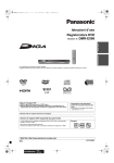
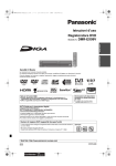
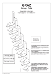
MANUALE PER L UTENTE SERVICE MANUAL M O N TA G G I O B A G A G L I E R A C K D CKD BAGGAGE RACK MOUNTING AVVERTENZE - Durante le operazioni di montaggio/smontaggio e le manutenzioni ordinarie, si consiglia di attenersi alle norme di sicurezza previste (D. Lgs 626) e di utilizzare abbigliamento adeguato (camici, occhiali, guanti, ecc.). - La ditta non assume nessuna responsabilità nè rilascia alcuna garanzia se il prodotto viene inserito in sistemi o montato con particolari che non siano di produzione della ditta stessa. La ditta si ritiene svincolata da qualsiasi indennizzo eventualmente richiesto dallacquirente per danni subiti o arrecati a terzi. WARNING - During assembly/disassembly operations and ordinary maintenance, follow the safety rules provided (D. Lgs 626) and wear suitable clothes (coats, goggles, gloves, etc.). - The Company disclaims all responsibility and will not release any warranty in case the product is installed on systems or used with components that have not been manufactured by the Company itself. The Company will not be held responsible for any customer claims due to damages suffered or caused to third parties. Nel caso di eventuali contestazioni del manuale, citare sempre il n° del lotto indicato sul sovrapacco In case of contentions about this manual, please refer to the lot number signed on the white label on the package 1 ⊗ Le informazioni contenute in questo manuale sono riferite allinstallazione di una bagagliera CKD completa di accessori (plance, bocchette aria, bocchette sbrinatore, ecc.). Ricordiamo però, che ogni bagagliera CKD viene studiata in modo diverso per ogni cliente, per cui alcune fasi del montaggio presenti in questo documento possono subire delle variazioni a seconda degli accessori installati. SCHEMA MONTAGGIO REGLETTE - REGLETTE MOUNTING SCHEME 213,5 PREFAZIONE - PREFACE ⊗ REGLETTE X 2 LUCE BLU NOTTURNA BLUE NIGHT LIGHT ⊗ Davanti Front 213,5 REGLETTE X 213,5 REGLETTE 213,5 4782 213,5 REGLETTE 213,5 REGLETTE The instructions contained in this manual are referred to the installation of a CKD luggage rack complete with accessories (service units, air diffuser vents, windshield defroster vents, etc.). However, we remind you that the way a CKD luggage rack is conceived changes for each customer, consequently some assembling steps as here reported and shown may be modified. MONTAGGIO REGLETTE - REGLETTE MOUNTING Materiale occorrente per 1 pezzo: 1 mancorrente (A); 5 reglette (B); 3 luce blu notturna (C); 1 passacavo per tubo (D); 1 cablaggio alimentazione reglette (E); 12 fermacavi (F); 3 fascette 6x23; 16 rivetti testa piana 3,2x9; 1 rivetto a 1 terminale L.6.3, 4x7. Required material for 1 piece: 1 profile for banister (A); 5 lighting assemblies (B); 3 blue night lights (C); 1 fairlead for tubes (D); 1 lighting assembly feeding harness (E); 12 wire locks (F); 3 clamps 6x23; 16 flush-head rivets for 3,2x9; 1-term. L.6.3, 4x7 rivet. Montaggio - Mounting: 1. Disporre il profilo per mancorrente (A) su di un piano e segnare la posizione delle reglette (B) e delle luci blu notturne (C) seguendo le misure riportate sul disegno di pag.3. 1. Arrange the banister profile (A) on a table and mark the position of the lighting assemblies (B) and the night blue lights (C) following the measures shown on the picture at page 3. 4. Creare 2 fori sul mancorrente in corrispondenza di ogni reglette; 1 in corrispondenza del centro della reglette, ed 1 a circa 5 cm da ogni reglette in direzione della testa. Una volta praticati i fori (10 in tutto), inserirvi i fermacavi (F). 4. Create 2 holes on the banister level with each lighting assembly, 1 at the centre of the lighting assembly and 1 at approximately 5 cm from each lighting assembly in the head direction. Once the holes have been drilled (total: 10 holes), introduce the wire locks (F). Foro - Hole Foro - Hole 5. Posizionare le basi di fissaggio delle luci blu notturne, forare in corrispondenza dei fori di fissaggio e fissarle con appositi rivetti. 5. Position the fastening base for the night blue lights, drill a hole at each fastening hole and fasten with the apposite supplied rivets. Base di fissaggio - Fastening base (A) 2. Posizionare le reglette sul mancorrente, forare in corrispondenza dei fori di fissaggio e fissarle con appositi rivetti. 2. Position the lighting assemblies onto the banister, drill a hole level with the fastening holes and fasten them with the apposite supplied rivets. (B) 6. Montare il cablaggio alimentazione reglette (E) facendolo passare attraverso il passacavo ed i fermacavi, e fermandolo con apposite fascette in corrispondenza delle reglette. Successivamente, stabilire le connessioni fra il cablaggio e le reglette. 6. Assemble the lighting assembly feeding harness (E) by making it pass through the fairlead and the wire locks, and then stopping it with the apposite supplied clamps at each lighting assembly. Successively, connect the harness to the lighting assemblies. (F) (E) 7. Per quanto riguarda lalimentazione della luce blu notturna, vi è una fase di preparazione in cui il cablaggio della stessa deve essere passato in uno dei fori della base di fissaggio; quindi viene inserita la lampadina, coperta con il guscio blu, ed infine si può stabilire la connessione con il cablaggio alimentazione reglette. 7. For the power supply of the night blue lights, a preliminary phase is needed where its harness must be prepared in one of the holes on the fastening base. Then, the lamp is inserted and covered with its blue shell. Finally, they can be connected to the lighting assembly feeding harness. Cablaggio reglette - Ruler harness 3. Creare un foro al centro del mancorrente ed a circa 2 cm dalla testa dello stesso; quindi inserirvi passacavo per tubo (D). 3. Create a hole at the centre of the banister and at approximately 2 cm from its head; then, introduce one fairlead for tube (D). (C) Guscio blu - Blue shell Lampadina - Lamp 8. Come ultima operazione, fissare il rivetto a 1 terminale e connettervi il cavo per la messa a terra. 8. As last operation, mount the 1-term rivet and connect the wire for the ground to it. (D) Rivetto a 1 term. - 1-term rivet 3 SCHEMA MONTAGGIO CANALI - GROOVES MOUNTING SCHEME Profilo elettrocolorato nero Black electrocoloured profile grove (H) making use of appropriate tools. (H) Profilo di rinforzo Reinforcement profile Canale superiore Upper groove Bocchetta P.123 (Cod.65582) P.123 diffuser (Code 65582) Bocchetta P.169 (Cod.64017) P.169 vent for window (Code 64017) Distanziale in ABS ABS spacing bar Canale inferiore Lower groove 2. Posizionare i distanziali in ABS (I) sul canale inferiore (H) con la U rivolta verso il canale seguendo le misure dei disegni di pag.6 e pag.10; quindi fermarli con bi-adesivo. 2. Position the ABS spacing bars (I) onto the lower groove (H) with the U shape towards the groove, following the measures shown in the pictures at pages 6 and 10; then, fasten them with the both-side adhesive tape. (I) Mensola di sostegno (Cod.62529) Bracket (Code 62529) Profilo mancorrente Profile for banister 4 MONTAGGIO - MOUNTING 1. Dopo aver segnato la posizione dei distanziali e delle plance (vedi disegni pagg. 6, 10, 11), ricavare le dime delle plance nel canale inferiore (H) utilizzando apposita strumentazione. 1. Sign the position of the spacing bars and multisets (see pictures pgs. 6, 10, 11), then drill the drilling templates on the lower 3. Rovesciare il canale. 3. Turn the groove upside down. 4. Praticare 4 fori in corrispondenza di ogni distanziale dopo averne segnato la posizione sul canale. Successivamente fissarli con appositi rivetti. 4. Drill 4 holes at each spacing bar, after you have marked their exact position on the groove. Successively, fasten them with the apposite supplied rivets. 6. Distribuire colla in corrispondenza del punto di contatto fra i distanziali ed il canale. 6. Distribute some glue at the points of contact between the spacing bars and the groove. 7. Posizionare il canale superiore (L) sui distanziali seguendo le misure riportate nei disegni di pag.6 e pag.10; quindi fermarlo con bi-adesivo. 7. Position the upper groove (L) onto the spacing bars, following the measures shown in the pictures at pages 6 and 10; then, fasten it with the both-side adhesive tape. (L) 5. Rovesciare il canale. 5. Turn the groove upside down. 5 ESEMPIO DI APPLICAZIONE - EXAMPLE OF APPLICATION A B C LATO DESTRO RIGHT SIDE D A B C LATO SINISTRO LEFT SIDE E D A) POSIZIONE MENSOLE DI SOSTEGNO (COD. 62529). B) POSIZIONE BOCCHETTE VANO OGGETTI (COD. 65582). C) POSIZIONE BOCCHETTE LATERALI (COD. 64017). D) POSIZIONE PLANCE MULTISET (COD. 62879-62869). E) POSIZIONE DISTANZIALI INTERMEDI. 6 A) BRACKETS POSITION (CODE 62529). B) P.123 AIR DIFFUSERS POSITION (CODE 65582). C) P.169 DEFROSTER VENTS POSITION (CODE 64017). D) MULTISETS POSITION (CODE 62879-62869). E) SPACING BARS POSITION . CAPPELLIERA COMPOSTA DA: - N. 12 MULTISET E P.158, 4 CON ALTOPARLANTE PER LATO (COD. 62869); - N. 18 BOCCHETTE SBRINATORE P.169 (COD. 65582); - N. 12 MENSOLE DI SOSTEGNO (COD. 62529); - N. 10 LAMPADINE FLUORESCENTI; - N. 6 LUCI BLU NOTTURNE; - N. 14 DIFFUSORI ARIA P.123 (COD. 64017). BAGGAGE RACK COMPOSED BY: - N. 12 MULTISETS P.158, 4 WITH LOUDSPEAKER ON BOTH SIDES (CODE 62869); - N. 18 DEFROSTER VENTS FOR WINDOW P.169 (CODE 65582); - N. 12 BRACKETS (CODE 62529); - N. 10 FLUORESCENT GLASSES; - N. 6 BLUE NIGHT LIGHTS; - N. 14 AIR DIFFUSERS P.123 (CODE 64017). 8. Praticare 4 fori in corrispondenza di ogni distanziale dopo averne rilevato la posizione sul canale. Successivamente, fermarli con appositi rivetti. 8. Drill 4 holes at each spacing bar, after you have marked their exact position on the groove. Subsequently, fasten them with the apposite supplied rivets. 11 - Dopo aver disposto la bagagliera e il tessuto baltic (N) su di un piano come mostrato in fig.1, spargere colla uniformemente su entrambe le superfici (fig. 2). 11 - When the baggage rack and the Baltic cloth (N) have been arranged on a table, as shown in picture 1, spread a uniform layer of glue on both surfaces (fig. 2). 1 2 (N) (N) 12 - Spostare il tessuto verso langolo del piano (fig. 3). 12 - Move the cloth towards the angle of the table (see fig. 3). (N) 3 9. Distribuire colla in corrispondenza dei punti di contatto fra i distanziali ed il canale. 9. Distribute some glue at the points of contact between the spacing bars and the groove. 13 - Rovesciare la bagagliera ed adagiarla sul tessuto in corrispondenza dellangolo del piano (fig. 4); quindi fare pressione per incollare la bagagliera al tessuto (fig. 5). 13 - Turn the baggage rack upside down and lay it on the cloth in the plane angle (fig. 4), then press until the baggage rack is glued to the cloth (see fig. 5). 5 4 14 - Capovolgere la bagagliera e quindi incollare il tessuto sulla restante superficie del canale superiore (fig. 6-7). 14 - Turn the baggage rack upside down and then glue the cloth on the remaining surface of the upper groove (see fig. 6-7). 10. Infilare il profilo di rinforzo (M) sul bordo superiore del canale superiore. 10. Insert the reinforcement profile (M) onto the upper edge of the upper groove. (M) 6 7 7 15 - Portarsi sul retro della bagagliera e, dopo avere sparso colla sul bordo superiore del canale superiore, riportarvi sopra il tessuto facendolo aderire alla superficie (fig. 8-9). 15 - From the back of the baggage rack, spread the glue on the upper edge of the upper groove and place the cloth on top of it until it adheres to the surface (see fig. 8-9). 19 - Rovesciare la bagagliera ed adagiarla sul tessuto; quindi fare pressione per incollare la bagagliera al tessuto (fig. 16). 19 - Turn the baggage rack upside down and place it on the cloth; press until the cloth is glued onto the baggage rack (see fig. 16). 16 - Sul retro della bagagliera rifilare la parte di tessuto in eccesso, e sul fronte liberare dal tessuto le dime che serviranno per linserimento delle bocchette aria (fig. 10-11). 16 - Trim the cloth in excess on the back of the baggage rack and extract the templates from the cloth on the front, which will be used later to introduce the air vent diffusers (see fig. 10-11). 20 - Capovolgere la bagagliera e quindi incollare il tessuto sulla restante superficie del canale inferiore (fig. 17-18). 20 - Turn the baggage rack upside down and glue the cloth on the remaining surface of the lower groove (see fig. 17-18). 17 - Come ultima operazione, incollare i lembi di tessuto alle estremità del canale al canale stesso (fig. 12-13). 17 - Finally, glue the borders of the cloth to the extremities of the groove (see fig. 12-13). 21 - Portarsi sul retro della bagagliera e, dopo avere sparso colla sul bordo superiore del canale inferiore, riportarvi sopra il tessuto facendolo aderire alla superficie (fig. 19-20). 21 - Go on the back of the baggage rack and spread the glue on the upper edge of the lower groove; then place the cloth over it until it adheres to the surface (see fig. 19-20). 9 8 11 10 12 13 17 18 19 18 - Capovolgere e disporre la bagagliera sul piano insieme al tessuto scamosciato (P), e quindi spargere colla uniformemente su entrambe le superfici come mostrato in fig. 14-15 18 - Turn the baggage rack upside down and place it on the plane together with the suede cloth (P); spread the glue uniformly on both surfaces, as shown in the figure 14-15. 20 22 - Dopo avere rifilato il tessuto in eccesso, liberare le dime delle bocchette sbrinatore e delle Multiset (fig. 21-22-23). 22 - Trim the cloth in excess and then extract the templates of the defroster hubs and the Multisets (fig. 21-22-23). 15 14 (P) 8 16 (P) 21 22 23 23 - Portarsi sul retro della bagagliera e infilare il profilo elettrocolorato (Q) sul bordo superiore del canale inferiore (fig. 24). Forare il profilo partendo a 10 cm dalla testa della bagagliera ed inserire rivetto; quindi ripetere loperazione ogni 90 cm circa fino a raggiungere laltra estremità della bagagliera (fig. 25-26). 23 - Go on the back of the baggage rack and insert the electrocoloured profile (Q) onto the upper edge of the lower groove (see fig. 24). Drill the profile starting at 10 cm from the head of the baggage rack and insert the rivet (Code 86773); repeat this action at 90-cm intervals until the other end of the baggage rack is reached (see fig. 25-26) 24 25 (Q) 24 - Sul fronte della bagagliera, allineare il profilo per mancorrente ai canali superiore ed inferiore ed infilarlo sugli stessi (bloccarlo con apposite pinze) (fig. 27-28). 24 - From the front of the baggage rack, line up the banister profile to the upper and lower grooves, and then insert it on them (block it with the special pliers) (see fig. 27-28). 27 - Infilare mensola di sostegno (R) con vite, dado e rosetta nelle apposite sedi del mancorrente e quindi fissarla pari alla testa della bagagliera (fig. 34-35). Ripetere loperazione per le altre 5 mensole seguendo le misure di fig. pag 8. 27 - Insert the bracket (R) with the screw, nut and washer into the special housings of the banister and then fasten it evenly at the baggage rack head (see fig. 34-35). Repeat this action for the other 5 brackets, based on the measures given in the figure at page 8. 34 35 (R) 28 25 - Forare il mancorrente in corrispondenza del bordo esterno del canale superiore e a circa 5 cm dalla testa della bagagliera; quindi fissare con rivetto. Ripetere loperazione ogni 25 cm circa fino a raggiungere laltra estremità della bagagliera (fig. 29-30). 25 - Drill the banister along the external edge of the upper groove and at about 5 cm from the head of the baggage rack; then fasten with a rivet. Repeat this action at 25-cm intervals until the other end of the baggage rack is reached (see fig. 29-30). 29 33 26 (Q) 27 32 31 28 - Capovolgere la bagagliera e forare il mancorrente in corrispondenza del bordo del canale inferiore a circa 5 cm dalla testa della bagagliera; quindi fissare con rivetto. Ripetere loperazione ogni 30 cm circa fino a raggiungere laltra estremità del mancorrente (fig. 36-37). 28 - Turn the baggage rack upside down and drill the banister along the edge of the lower groove at about 5 cm from the head of the baggage rack; then fasten with a rivet. Repeat this action at about 30-cm intervals until the other end of the banister is reached (see fig. 36-37). 36 37 30 29 - Infilare le bocchette sbrinatore P.169 (S) nelle apposite dime (fig. 38) e fissarle internamente con colla (fig. 39). 29 - Insert the P.169 defroster vents (S) into the special templates (fig. 38) and fasten them with some glue internally (see fig. 39). 26 - Distribuire colla Bostik sul mancorrente in corrispondenza del bordo del canale superiore e quindi incollarvi sopra il tessuto. Successivamente, rifilare il tessuto in eccesso (fig. 31-32-33). 26 - Spread Bostik glue onto the banister along the edge of the upper groove and then glue the cloth upon it. Subsequently, trim the cloth in excess (see fig. 31-32-33). 38 39 (S) 9 30 - Posizionare i diffusori aria P.123 (T) sulle dime corrispondenti e fissarli con viti autofilettanti (fig. 40). 30 - Position the P.123 air diffusers (T) onto the corresponding templates and fasten them with the self-tapping screws (see fig. 40). 40 33 - Forare il canale inferiore in corrispondenza della dima della Multiset rispettando le misure degli interassi dei fori di fissaggio (fig. 47). Successivamente, applicare una piastrina per vite autofilettante in corrispondenza di ogni foro (fig. 48). 33 - Drill the lower groove along the template of the Multiset, according to the measures of the centre distances of the fastening holes (fig. 47). Subsequently, place one plate for each self-tapping screw at each hole (see fig. 48). 47 48 (T) 31 - Sul retro, partendo dalla mezzeria della prima plancia di testa, fissare il fermacavo biadesivo (U) posizionandolo circa a metà della larghezza del canale superiore; quindi infilarvi una fascetta. Ripetere loperazione per gli altri 6 fermacavi tenendo come riferimento gli interassi delle plance (fig. 41). Fissare il cablaggio per alimentazione plance (V) al canale superiore fermandolo con le fascette (fig. 42-43). 31 - On the back, starting from the centre line of the first head Multiset, fasten the both-side adhesive wire lock (U) by positioning it at about half the length of the upper groove; then, insert a clamp. Repeat this action for the other 6 wire locks referring to the centre distances of the Multisets (fig. 41). Fasten the Multiset feeding harness (V) to the upper groove by means of the clamps (see fig. 42-43). (U) 41 34 - Collegare le connessioni del cablaggio alimentazione Multiset alle rispettive connessioni sulla Multiset (fig. 4950). Successivamente, rovesciare la Multiset inserendola nella dima corrispondente (fig. 51). 34 - Connect the Multiset feeding harness cables to their respective connections on the Multiset (fig. 49-50). Subsequently, turn the Multiset upside down and insert it into the corresponding template (see fig. 51). 49 42 43 35 -Testare il corretto funzionamento della Multiset con apposita strumentazione e quindi procedere nel fissaggio con viti autofilettanti (fig. 52-53). Alla fine, inserire i coprivite nelle apposite sedi sulla Multiset (fig. 54). Ripetere i passaggi da 22 a 25 per tutte le Multiset 35 -Test that the Multiset is working correctly by means of the special-purpose tools and then fasten it with selftapping screws (see fig. 52-53). Finally, insert the screw caps into their special housings on the Multiset (see fig. 54). Repeat the actions from 22 to 25 for all the Multisets. 52 10 51 (V) 32 - Montare 2 lampadine sui portalampade della Multiset ed inserirle nei gruppi luce (fig. 44-45-46). 32 - Assemble 2 lamps onto the lamp holders of the Multiset and insert them into the lighting units (see fig. 44-45-46). 44 50 45 46 53 54