1
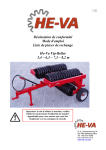
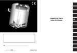
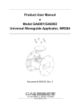
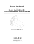
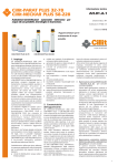
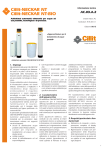
Declaration of Conformity
Operating Instructions
Spare Part List
UK
HE-VA Vip-Roller 5.4
6.3 m
N. A. Christensensvej 34
DK-7900 Nykøbing Mors
Tel: 9772 4288
Fax:9772 2112
www.he-va.com
Contents
Declaration of Conformity .......................................................................................... 3
1.
Delivery Check .............................................................................................................. 4
2.
Specifications ................................................................................................................. 4
3.
Operating Instructions
3.1 Attachment................................................................................................................ 5
3.2 Transport ................................................................................................................... 5
4.
Maintenance
4.1 Rolling. ..................................................................................................................... 6
4.2 Lubrication................................................................................................................ 6
5.
Spare Part List
5.1 Tail, Chassis, Centre Section, Wheel Frame etc. ...................................................... 7
5.2 Axles and Bearings.................................................................................................... 10
5.3 Roller Rings............................................................................................................... 11
5.4 Hydraulics ................................................................................................................. 13
6.
Hydraulic Diagram
6.1 Hydraulic diagram for 5.4 and 6.3 m........................................................................ 14
7.
Notes ............................................................................................................................... 15
Vip-Roller
11-02-03
DS/EN 45 014
Declaration of Conformity
HE-VA A/S
N. A. Christensensvej 34,
DK-7900 Nykøbing Mors
declares under our sole responsibility that the product:
Vip-Roller 5.4 / 6.3 m
Types 4542, 4543, 4544, 4545, 4546, 4547
4632, 4633, 4634, 4635, 4636, 4637,
to which this declaration relates
is in conformity with the provisions of
98/392/EEC (Machinery) Directive with later amendments.
Nykøbing Mors 11.02.03
3
Vip-Roller
11-02-03
1. Delivery Check
Check the roller for any damages. Check the hydraulic hoses for cuts and squeezing damages. Check
also that the other hydraulic components have not been damaged during transport.
Check that the frame construction has not been damaged. You should also check that the roller
blocks have not been exposed to impacts, which may have damaged the cast roller rings or the
double-sealed ball bearings.
Finally check that the transport wheels are tightened and OK.
Check the air pressure in the tyres: approx. 3.8 bar / 55 psi
2. Specifications
3-section hydraulic wheel-mounted field roller with free movability in all sections. Used for
rolling of stones and packing of the top soil. The roller is available with a working width of 5.4
m or 6.3 m and with three different ring types: Cambridge, cam and Crosskill rings.
Technical Specifications
Working Width................................................................................................................5.4 / 6.3 m
Total width (folded out) ..................................................................................................5.7 / 6.6 m
Length..............................................................................................................................3.4 / 3.8 m
Transport width .....................................................................................................................2.45 m
Transport height ....................................................................................................................1.60 m
Pressure on pintle eye in transport position (% of total weight) ................................ approx. 40 %
Wheel assembly, standard ...................................................................................10.0/80 x 12.8 PR
Tyre pressure ............................................................................................................3.8 bar / 55 psi
Requirement for tractor hydraulics:
Oil pressure ................................................................................................................. min. 150 bar
PTO .................................................................................1 single-acting and 1 double-acting PTO
Quick-couplings, standard.................................................................................Sterling type E 402
Hydraulic oil: The system is filled with .....................................................................Agip OSO 32
Width 5.4 m
Width 6.3 m
Qty.
Weight
Qty.
Weight
Rings
kg
Rings
kg
Cambridge, ø45 cm/18"
105
1840
129
2460
Cambridge, ø51 cm/21"
105
2015
129
2670
Cam, ø55 cm
36
1530
42
2120
Crosskill, ø48/ø53 cm
54
1980
63
2550
Ring type
4
Vip-Roller
11-02-03
3. Operating Instructions
3.1 Attachment
On delivery the roller is in transport position. When the roller is attached, check that the towing
hook height is 400-500 mm. Reverse the tractor, put in and secure the draw bolt.
Raise the support leg and place it in the transport fittings on top of the tail. Now fit the three
hydraulic hoses. The roller requires one double-acting and one single-acting PTO.
Now fit the hydraulic in the tractor PTO. Important: Check that the male end mounted by the
factory fits the female end of the tractor.
Now pressurise the tip cylinder so that the side sections are tipped free of the transport fittings. Then
the side sections are turned out by means of the wing cylinder.
Now the roller is hydraulically tipped into working position by means of the tip cylinder.
3.2 Transport
At change-over for transport, the roller is tipped totally backward by pressurising the tip cylinder.
Now pressurise the wing cylinder so that the side sections turn forward, towards the stop on the
transport fittings of the tail.
When both sides lie in parallel with the tail, they are lowered down into the transport fittings by
unpressurising the tip cylinder.
Now relieve the hydraulics totally, and the roller is ready for transport.
5
Vip-Roller
11-02-03
4. Maintenance
A.
B.
C.
After approximately 10 hours of operation, the wheels, ball bearings, check pawl console
and stop rings shall be retightened. Check hoses, fittings and cylinders for any leaks and
retighten.
After every approximately 30 hours of operation, lubricate the tip cylinder rivets and the
two lubricating points of the side sections with grease.
After the season, clean the roller and lubricate with grease and oil.
NOTE:
The double-sealed ball bearing should only be greased
1-2 strokes so that the sealing rings are not pressed out.
4.1 Rolling
Speed: max. 10 km/h.
When turning, drive in wide curves as far as possible. The turning should not be performed so
sharply that all roller rings cannot still rotate forward.
Only lower the wheels in connection with folding up for transport position.
Do not drive over large and earthfast stones.
4.2 Lubrication
After every 10 hours of operation, lubricate
- the suspension of the individual roller
sections
- the hinges of the outer sections on the inner
section.
After every 30 hours of operation, lubricate
-
Once a year, lubricate
- the support leg
IMPORTANT
the vertical hinge of the inner wings
the ball bearings
the cylinders
the hinges of the wheel frame on the chassis
Only lubricate the ball bearings 1-2 strokes as the
sealing rings may otherwise be pushed out.
6
Vip-Roller
11-02-03
5. Spare Part List
5.1 Tail, Chassis, Centre Section, Wheel Frame, etc.
7
Vip-Roller
Pos.
1
1
1a
1b
2
2
2a
3
4
4a
4b
5
5a
5b
6
7
7
7
8
9
10
10a
10b
10c
11
11
11a
11b
11c
11d
11e
11f
11g
12
12a
12b
13
14
15
16
16
16
16
17
Item. No.
5,4m
631630400
631630300
690103126
690113008
690210210
690210211
690102050
630640100
690141100
630552100
690133005
630554300
690101101
630532600
690200120
630530300
630530400
630530500
690112009
690101164
690142001
690103015
690117002
690113002
630650200
630651000
690141023
690141040
690141055
690140101
690140103
690141075
690141035
630650700
690101101
630532600
630650500
630650600
690141010
630640400
630640900
630640300
630640800
630532300
11-02-03
Item. No.
6,3m
631630400
631630300
690103126
690113008
690210210
690210211
690102050
630650100
690141100
630552100
690133005
630554300
690101101
630532600
690200120
630530300
630530400
630530500
690112009
690101164
690142001
630103015
690117002
690113002
630650200
630651000
690141023
690141040
690141055
690140101
690140103
690141075
690141035
630650700
690101101
630532600
630650500
630650600
690141010
630650400
630650900
630650300
630650800
630532300
Destination
Hitch hook D
Hitch hook DK
Bolt M16x45
Self-locking nut M16
Double hose support ø14 mm
Top plate
Bolt M8x35
Tail
Support leg
Support leg rivet ø16
Split-pin ø4 mm
Rivet ø30 L=135 mm
Bolt M12x25
Locking sleeve for rivet head
Cylinder 80/40x600 ø30/ø30
Transport fittings ø470 mm
Transport fittings ø530 mm
Transport fittings ø550 mm
Nut M20
Bolt M20x60
Warning triangle
Bolt M5x25
Faceted disc ø5
Self-locking nut M5
Centre frame for shaft ø50
Centre frame for shaft ø60
Hub 3552, 5/102/140 complete
Hub bolt M12x1,5x31
Hub nut
Bearing 30206
Bearing 30208
Sealing ring
Hub cover
Rivet ø30 L=685
Bolt M12x25
Locking sleeve for rivet head
Wing cylinder 70/40x600, ø30
Bush ø45/ø31 L=50mm
Wheel 10.0/80x12,8 pr
Outer section, left, for axle ø50
Outer section, left, for axle ø60
Outer section, right, for axle ø50
Outer section, right, for axle ø60
Rivet ø30 mm L=85mm
8
Qty.
1
1
4
4
2
2
2
1
1
1
1
3
2
2
1
2
2
2
1
1
1
2
2
2
1
1
2
10
10
2
2
2
2
1
2
2
1
1
2
1
1
1
1
2
Vip-Roller
17a
17b
18
690101101
630532600
690136029
11-02-03
690101101
690532600
690136029
Bolt M12x25
Locking sleeve for rivet head
Lubrication nipple M8x1,25
9
2
2
3
Vip-Roller
11-02-03
5.2 Axles and Bearings
Pos.
Item No 5,4 m
Item No 6,3 m
Designation
Qty
1
678542370
Axel f/centre section Ø50 St70
1
678541940
Axel f/side section Ø50 St70
1
678652370
Axel f/centre section Ø60 St70
L=2370
1
1
678651940
Axel f/centre section Ø60 St70
L=1940
2
L=2370
L=1940
1
2
1
678542370
Axel f/centre+side section Ø50 St70
L=2370
3
1
678652370
Axel f/centre+side section Ø60 St70
L=2370
3
2
630552300
630552300
Stop ring w/bolt Ø50 mm
6
2
630651200
630651200
Stop ring w/bolt Ø60 mm
6
2a
690101080
690101080
Bolt M10x25
12
3
690140801
690140801
Bearing, SFT45
6
3
690140804
690140804
Bearing SFT60
6
3a
690103128
690103128
Bolt M16x55
12
3b
690117008
690117008
Faceted disc Ø 16
12
3c
690113008
690113008
Self-locking nut
12
10
Vip-Roller
11-02-03
5.3 Roller Rings
Aggresive
Lenient
11
Vip-Roller
11-02-03
Qty.
Qty.
Designation
5.4
6.3
Pos.
Item No.
1
690150001
Cambridge smooth ring 15" (ø50) Aggresive
55
63
2
690150004
Cambridge serrated ring 15" (ø50) Aggresive
52
60
1
690150031
Cambridge smooth ring 18" (ø50) Lenient
55
63
1
690150017
Cambridge smooth ring 18" (ø50) Aggresive
55
63
1
690150039
Cambridge smooth ring 18" (ø60) Lenient
55
63
2
690150033
Cambridge serrated ring 18" (ø50) Lenient
52
60
2
690150018
Cambridge serrated ring 18" (ø50) Aggresive
52
60
2
690150040
Cambridge serrated ring 18" (ø60) Lenient
52
60
1
690150019
Cambridge smooth ring 21" (ø50) Aggresive
55
63
1
690150030
Cambridge smooth ring 21" (ø60) Lenient
55
63
1
690150024
Cambridge smooth ring 21" (ø60) Aggresive
55
63
2
690150009
Cambridge serrated ring 21" (ø50) Aggresive
52
60
2
690150032
Cambridge serrated ring 21" (ø60) Lenient
52
60
2
690150025
Cambridge serrated ring 21" (ø60) Aggresive
52
60
3
690150007
Cam ring 22" (ø50)
36
42
4
690150011
Loose Crosskill ring 530 mm
26
30
5
690150012
Hub for loose Crosskill ring Ø50
26
30
5
690150035
Hub for loose Crosskill ring Ø60
26
30
6
690150010
Crosskill ring ø485 mm (ø50)
29
33
6
690150034
Crosskill ring ø485 mm (ø60)
29
33
7
690150013
Corrugated ring ø500 mm (ø60)
113
129
8
690150028
Flat ring ø505 mm (ø60)
19
21
12
Vip-Roller
11-02-03
5.4 Hydraulics 5.4 m and 6.3 m
Pos.
Item No.
Designation
Qty.
1
690203001
Quick-coupling ½" E402
3
2
690210001
Dust capC51 blue
2
3
690210002
Dust cap C51 red
1
4
690203003
Straight joint GA10LR ½ O.D.
3
5
690201107
Hose 1/4" L = 5350 mm
2
6
690201066
Hose 1/4" L = 3300 mm
1
7
690203006
Angle joint , VA10LK 3/8 O.D.
3
8
690206001
Filter plug F38 3/8"
1
9
690200020
Wing cylinder 70/40x600 ø30
1
10
690200120
Cylinder 80/40x600 ø30/ø30
1
11
690207901
Throttle 1mm
2
13
Vip-Roller
11-02-03
6. Hydraulic Diagram
6.1 Hydraulic Diagram for 5.4 m and 6.3 m
Pos.
Item No.
Designation
Qty.
1
630650600
Wing cylinder 70/40x600 ø30
1
2
690200120
Cylinder 80/40x600 ø30/ø30
1
3
690206001
Filter plug F38 3/8"
1
4
690203001
Quick-coupling E402
3
5
690207901
Throttle 1 mm
2
14
Vip-Roller
11-02-03
7. Notes
15
The design is subject to modification without notice.