1
INSTALLATION MANUAL
Address card
EKAC10B
1
2
Serial module
88
44
µchiller
Serial
module
compact
µchiller
compa
70
ct
64
1
2
3
4a
4b
12 11
G G0
power supply
12 11
G G0
power supply
Serial module
Serial module
1
µchiller
µchiller
compact
compact
Serial module
µchiller
compact
50 51
50 51
2
4a
5a
4b
5b
3
4
3
5a
5b
Installation manual
Address card
EKAC10B
READ THIS MANUAL ATTENTIVELY BEFORE STARTING
UP THE UNIT. DO NOT THROW IT AWAY. KEEP IT IN
YOUR FILES FOR FUTURE REFERENCE.
IMPROPER INSTALLATION OR ATTACHMENT OF
EQUIPMENT OR ACCESSORIES COULD RESULT IN
ELECTRIC SHOCK, SHORT-CIRCUIT, LEAKS, FIRE OR
OTHER DAMAGE TO EQUIPMENT. BE SURE ONLY TO
USE ACCESSORIES MADE BY DAIKIN THAT ARE
SPECIFICALLY DESIGNED FOR USE WITH THE
EQUIPMENT AND HAVE THEM INSTALLED BY A
PROFESSIONAL.
IF UNSURE OF INSTALLATION PROCEDURES OR USE,
ALWAYS CONTACT YOUR DAIKIN DEALER FOR ADVICE
AND INFORMATION.
DESCRIPTION
Measurements
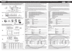
(refer to figure 1)
Connections on the address card
There are three connections to be made:
■
to the chiller’s controller
■
power supply
■
if the kit is used in combination with gateway, connect to the
serial line of the gateway
OR
if the kit is used in combination with the remote user interface,
connect to the remote user interface
INTRODUCTION
Before starting up the unit for the first time, make sure that
it has been properly installed. It is therefore necessary to
read the installation manual supplied with the unit and the
recommendations listed in “Checks before initial start-up”
carefully.
Thank you for purchasing the EKAC10B address card.
This address card will enable you to communicate with your chiller
through a Building Management System or supervisory system.
Please refer to the Gateway Installation Manual for more information
and a detailed overview of how the communication works.
OR
This address card will enable you to connect a remote user interface.
Please refer to the installation manual of the remote user interface
EKRUMC for more detailed information.
CHILLER
Connection
Switchbox
EUWA5~12H*(Z)
EUWY5~10H*(Z)
EUW5~24HZ
EUWL5~24HZ
Refer to figure 4a
50/51 on terminals
Omega rail available
2
EUWAC5~10FZ
Refer to figure 4a
50/51 on terminals
Omega rail available
3
EUWAN5~24KZ
EUWAP5~24KZ
EUWAB5~24KZ
EUWYN5~24KZ
EUWYP5~24KZ
EUWYB5~24KZ
Refer to figure 4b
G and G0
on I/O PCB
Refer to figure 5a
Installation possible
of omega rail
EUW5~12KZ
EUWL5~12KZ
Refer to figure 4b
G and G0
on I/O PCB
Refer to figure 5b
Installation possible
of omega rail
EUW16~24KZ
EUWL16~24KZ
Refer to figure 4b
G and G0
on I/O PCB
Omega rail available
1
4
5
YOUR
Models
HOW
TO INSTALL THE ADDRESS CARD?
Turn the power off before installing the address card.
Install the address card
RANGE
This specific address card is designed to function with chillers of the
ranges according to the following table.
Range
OF THE ADDRESS CARD
For range 3 and 4 only
Install the omega rail on the foreseen space
range 3, refer to figure 5a
range 4, refer to figure 5b
For all ranges
(refer to figure 2)
Place the address card on the upper side of the omega rail, then
push the bottom side of the address card until you hear a clicking
sound. The address card is now locked onto the omega rail.
If you want to remove the address card because it was installed
incorrectly, follow this procedure:
1
Pull down the grey lip at the bottom of the address card, using a
screwdriver.
2
Keep the lip down and pull the bottom side of the address card
backwards.
3
Raise the address card and release the lip.
ADDRESS CARD KIT
The kit you have just purchased consists of:
■
1 address card (type EKAC10B)
■
1 connection wire to controller
■
1 connection wire + 1 connection wire with fuse (power supply)
■
1 omega rail + 2 screws
EKAC10B
Address card
4PW16026-1A
Installation manual
1
Connect the address card to the controller
For ranges 3, 4 and 5 only
(refer to figure 3)
(refer to figure 4b)
Use the grey connection wire to connect the address card to the
controller.
1
Connect screw connection 11 G0 on the address card to
terminal G0 on the I/O PCB. Use the supplied connection wire
without fuse.
2
Connect screw connection 12 G on the address card to terminal
G on the I/O PCB. Use the supplied connection wire with fuse.
1
Push the crimp terminal of the connection wire in the 7-pin
header on the upper side of the address card.
2
Unplug the wire in the right upper corner at the back of the
controller. This way you will create enough space to plug in the
connection wire.
3
Push the crimp terminal on the other side of the connection wire
in the 7-pin header at the back of the controller. The 7-pin
header is called the serial line on the figure at the top of the
controller.
4
Plug in the wire you removed to create enough space back in the
top right corner at the back of the controller.
HOW
TO OPERATE THE ADDRESS CARD WITH
THE GATEWAY?
Connect the address card to the gateway or to a
different address card
You have two possibilities:
■
If the chiller is the first in line or the only one to connect to a
gateway, connect it to the gateway directly.
■
If the chiller is a chiller in line and not the first one in line,
connect it to another chiller.
Connect the address card to the transfo
For ranges 1 and 2 only
(refer to figure 4a)
For more information, consult the following documents:
Use the connection wire and the connection wire with fuse to connect
the address card to the transfo.
■
The chiller operation manual: Defining the unit’s serial address.
■
Installation manual of gateway.
1
Connect screw connection 11 G0 on the address card to
terminal 50 on the main rail. Use the supplied connection wire
without fuse.
■
Operation manual of gateway.
2
Connect screw connection 12 G on the address card to terminal
51 on the main rail. Use the supplied connection wire with fuse.
HOW
TO OPERATE THE ADDRESS CARD WITH
THE REMOTE USER INTERFACE?
Read more on this in the installation manual of the remote user
interface EKRUMC.
THE
VARIABLES DATABASE only for use with Gateway
The BMS or supervisory system and the address card communicate
through a fixed set of variables, also called address numbers.
Hereafter, you will find the information you need about the digital,
integer and analog variables that the BMS or supervisory system can
read from or write to the chiller’s address card.
NOTE
For the possible values of a direct or user parameter,
refer to the chiller operation manual.
Digital variables
Parameter
Comment
Water cooled
chillers
Air cooled
chillers
Address
1
r/w
Cooling or heating
1 = cooling, 0 = heating
2
r/w
On or off
1 = on, 0 = off
5
r
H1
Alarm: high pressure or discharge protector or overcurrent
1 = alarm, 0 = no alarm
6
r
L1
Alarm: evaporating temperature thermostat
1 = alarm, 0 = no alarm
8
r
FL
Alarm: flow switch
1 = alarm, 0 = no alarm
9
r
E3
Alarm
Ambient
temperature (a)
10
r
E2
Alarm
Water evaporator outlet temperature
11
r
E1
Alarm
Water evaporator inlet temperature
12
r
n1
Warning: compressor requires maintenance
1 = warning, 0 = no warning
13
r
EP
Alarm: EEPROM defective
1 = alarm, 0 = no alarm
r
EE
Alarm: EEPROM defective
1 = alarm, 0 = no alarm
14
Direct/
User
Air cooled
chillers
Read/
Write
Name
Description
Coil
temperature (a)
Remote
Condenser
Water
condenser inlet
temperature
(a) Only if model is mentioned in range 1
Installation manual
2
EKAC10B
Address card
4PW16026-1A
Parameter
Comment
Water cooled
chillers
Direct/
User
Air cooled
chillers
Air cooled
chillers
Address
Read/
Write
15
r
EL
Alarm: power supply has remarkable noise
1 = alarm, 0 = no alarm
17
r
d1
Defrost cycle
1 = active, 0 = not active
18
r
r1
Warning: defrost cycle not completed
1 = warning, 0 = no warning
19
r
A1
Alarm: anti-freeze
1 = alarm, 0 = no alarm
21
r
EO
Alarm: supply voltage is high
1 = alarm, 0 = no alarm
22
r
EU
Alarm: supply voltage is low
1 = alarm, 0 = no alarm
25
r
Output of pump
1 = on, 0 = off
26
r
Output of compressor 1
1 = on, 0 = off
28
r
Output of reversing valve
—
29
r
Output of alarm
1 = on, 0 = off
30
r
Output of fan
1 = on, 0 = off (a)
31
r
Input of high pressure or discharge protector or overcurrent alarm
1 = closed, 0 = open
32
r
Input of low pressure switch alarm
1 = closed, 0 = open
33
r
Input of remote on/off
1 = closed, 0 = open
34
r
Output of compressor 2 (b)
1 = on, 0 = off
40
r/w
/d
Measurement unit of temperature
0 = °C, 1 = °F
47
r/w
H7
Enable/disable "remote on/off" digital input
1 = enable, 0 = disable
55
r/w
H6
Enable/disable "remote cooling/heating" digital input
1 = enable, 0 = disable
57
r
n2
Warning: compressor 2 requires maintenance (b)
1 = warning, 0 = no warning
Name
Remote
Condenser
Description
1 = on, 0 = off
—
(a) Only if model is mentioned in range 1
(b) Only available for units with 2 circuits
Integer variables
Parameter
Address
Read/
Write
Direct/
User
Name
Comment
Unit of measurement
12
r/w
U
c7
Time delay between the pump startup and compressor startup
Seconds
13
r/w
U
c8
Time delay between unit shutdown and the pump shutdown
Minutes
14
r
D
c9
Total running hours of the compressor 1
Hours x 100
15
r/w
U
cb
Timer threshold for maintenance warning
Hours x 100
16
r
D
cC
Total running hours of the pump
Hours x 100
32
r/w
U
P4
Enable or disable buzzer
38
r/w
U
H9
Lock of user & direct parameters
39
r
U
HA
Serial address
51
r
U
Hg
Software release
55
r
D
cA
Total running hours of the compressor 2 (a)
Description
0 = keyboard disabled, 1 = keyboard enabled
Hours x 100
(a) Only available for units with 2 circuits
Analog variables (Unit of measurement: °C x 1/10)
Parameter
Comment
Water cooled
chillers
Direct/
User
Air cooled
chillers
Air cooled
chillers
Remote
Condenser
Address
Read/
Write
1
r
Analog input 1
Water evaporator inlet temperature
2
r
Analog input 2
Water evaporator outlet temperature
3
r
Analog input 3
Ambient
temperature (a)
10
r/w
D
r1
Cooling setpoint
11
r/w
D
r2
Cooling difference
12
r/w
D
r3
Heating setpoint
—
13
r/w
D
r4
Heating difference
—
Name
Description
Coil
temperature (a)
Water
condenser inlet
temperature
(a) Only if model is mentioned in range 1
EKAC10B
Address card
4PW16026-1A
Installation manual
3
Zandvoordestraat 300, B-8400 Oostende, Belgium
4PWEN16026-1A