Transcript
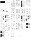
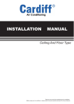
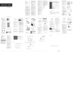
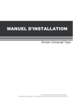
When installing the unit in a small room, take measures
against to keep refrigerant concentration from exceeding
allowable safety limits in the event of refrigerant leakage.
Contact the place of purchase for more information.
Excessive refrigerant in a closed ambient can lead to oxygen
deficiency.
2. INSTALLATION INFORMATION................................................ 2
3. ATTACHED FITTINGS ...................................................... 3
4. INSPECTING AND HANDLING THE UNIT........................ 4
5. INDOOR UNIT INSTALLATION......................................... 4
6. OUTDOOR UNIT INSTALLATION.................................... 9
7. REFRIGERANT PIPE....................................................... 12
8. INSTALL THE CONNECTING PIPE................................. 14
11. TEST OPERATION......................................................... 18
MANUAL
The appliance must be installed 2.3m above floor.
The appliance shall not be installed in the laundry.
1. PRECAUTIONS
Four-way Cassette Type
Be sure to be in conformity with the local, national and
international laws and regulations.
The appliance must be positioned so that the plug is
accessible.
Read "PRECAUTIONS" carefully before installation.
The enclosure of the appliance shall be marked by word,
or by symbols, with the direction of the fluid flow.
The following precautions include important safty items.
Observe them and never forget.
For electrical work, follow the local national wiring
standard, regulation and this installation instructions. An
independent circuit and single outlet must be used.
If electrical circuit capacity is not enough or defect in
electrical work, it will cause electrical shock or fire.
Keep this manual with the owner's manual in a handy place
for future reference.
Use the specified cable and connect tightly and clamp
the cable so that no external force will be acted on the
terminal.
If connection or fixing is not perfect, it will cause heat-up or
fire at the connection.
The safty precautions listed here are divided into two categories.
WARNING
Failure to observe a warning may result in death.
Failure to observe a caution may result in injury or
damage to the equipment.
Be sure only trained and qualified service personnel to
install, repair or service the equipment.
Improper installation, repair, and maintenance may result in
electric shocks, short-circuit, leaks, fire or other damage to
the equipment.
Tubing joint
Hook panel
panel
panel foam1
14. Installation hook
4
Installation accessory
(The product you have might not be
provided the following accessory)
Install the indoor unit;
Install the outdoor unit;
Install the connecting pipe ;
15 .Orifice
Keep the remote controller at least 1m apart from the nearest TV set or stereo
equipment. (it is necessary to prevent image disturbances or noise interferences.)
6.1 Installation Place
All the pictures in this manual are for explanation purpose only.
They may be slightly different from the air conditioner you
purchased(depend on model).The actual shape shall prevail.
Ø75mm
There is enough room for installation and maintenance.
4
5
Fig.5-16
Fig.5-13
Installation cover’s rope
Tap Screw
Slide the four sliders
in the corresponding
channel when installing
the cover
1
Remove the test cover, and stow about 2000ml water to the
water pan.
2
Operate the air conditioner in "COOLING" mode. The sound of
the drain pump shall be heard. Check whether the water is
discharged well (1 min lag is possible, according to the length of
the drain pipe), and check whether the water leaks from the
joints.
Fig.5-14
3
>60cm
>30cm
B
1120
720
30~36
1338
820
1338
To change air outlet is necessary to interchange panels too.
100 300
≥100
00
mm
Fig.6-12
Fig.6-16
Fig.6-14
Table 6-4
NOTE
Keep in mind that fan unit weight is aprox 30kg ,the unit as
Description
Note: Reduced length of the branching tube is the 0.5m of
the equivalent length of the pipe.
1
Outdoor Unit
Table.7-1
2
Vibration-proof rubber
6
during installation work.
installation manual
11
Install the drain joint of the outdoor unit
NOTE
1
Pipe length
Anchor Bolt M10
Drainage (Wide 100×Depth 150)
Drainage
Mortar Hole (Φ100×Depth 150)
The base pan hole
of outdoor unit
Seal
3
For detailed installation acceptance please refer to your
power supplier, if restrictions do apply for products like
washing machines, air conditioners or electrical ovens.
4
For power details of the air conditioner refer to the rating
plate of the product.
5
For any question contact your local dealer.
NOTE
All the pictures in this manual are for explanation
purpose only. They may be slightly different from the
air conditioner you purchased(depend on model).The
actual shape shall prevail.
Protection Board
(farthest from the line
pipe branch)
(farthest from the line
pipe branch)
Indoor unit-outdoor unit
drop height
15m
10m
20m
Indoor unit to indoor unit drop height
0.5m
L1,L2
L1-L2
H1
H2
The test operation must be carried out after the entire
installation has been completed.
The length of the tubing and the added stow capacity of
the refrigerant have been recorded.
3
NOTE
All the pictures in this manual are for explanation
purpose only. They may be slightly different from the
air conditioner you purchased(depend on model).The
actual shape shall prevail.
(Refer to Table10-1~Table10-8)
1.
2.
3.
Fig.10-1
1. Close-off the valve of
vacuum meter.
2. Cut off the connection
between pressure meter
and vacuum pump.
3. Close the vacuum
pump.
Fig.10-8)
4.
Remove the electric parts cover from the outdoor unit.
Connect the connective cables to the terminals as identified
with their respective matched numbers on the terminal block
of indoor and outdoor units. (Connective cable sheath
length to be removed and insert into the terminal block.)
To prevent the ingress off water, from a loop of the
connective cable as illustrated in the installation diagram of
indoor and outdoor units.
Insulate unused cords (conductors) with PVC-tape. Process
them so they do not touch any electrical or metal parts.
Vertical discharge type outdoor unit
4
Horizontal surface
Fig.7-3
According to the user's requirement, install the remote
controller frame where the remote controller's signal can
reach the indoor unit smoothly.
Test operation
Set the air conditioner under the mode of "COOLING" with the
remote controller, and check the following points. If there is
any malfunction, please resolve it according to the chapter
"Troubleshooting" in the "Owner's Manual".
1) The indoor unit
a. Whether the switch on the remote controller works well.
b. Whether the buttons on the remote controller works
well.
c. Whether the air flow louver moves normally.
d. Whether the room temperature is adjusted well.
e. Whether the indicator lights normally.
f. Whether the temporary buttons works well.
g. Whether the drainage is normal.
h. Whether there is vibration or abnormal noise during
operation
I. Whether the air conditioner heats well in the case of the
HEATING/COOLING type.
2) The outdoor unit
a. Whether there is vibration or abnormal noise during
operation.
b. Whether the generated wind, noise, or condensed of by
the air conditioner have influenced your neighborhood.
c. Whether any of the refrigerant is leaked.
NEW FAN
MOTOR
Fig.10-9 (the figure is for the unit with the new fan function)
the power of new fan motor is more than 200W
INDOOR UNIT
The design and specifications are subject to change without prior notice for product
improvement.Consult with the sales agency or manufacturer for details.
N
DC RELAY/
AC CONTACTOR
CAUTION
The wiring must be operated according to the wiring scheme,or it damages the unit.
Before obtaining access to terminals, all supply circuits must be disconnected.
202000192390
20130923
23
Fig.6-2
760
530
290
315
270
285
590
Fig.6-2
845
560
335
360
312
320
700
Fig.6-2
852
582
368
390
328
340
660
Fig.6-2
900
590
333
355
302
315
860
Fig.6-2
990
624
366
396
340
345
965
Fig.6-2
990
624
366
396
340
345
965
Fig.6-2
900
590
333
355
302
315
860
Fig.6-2
990
624
366
396
340
345
965
Fig.6-2
938
634
404
448
368
392
1369
Fig.6-3
990
624
366
396
340
345
965
Fig.6-2
938
634
404
448
368
392
990
624
366
396
340
345
965
900
590
378
400
330
350
1170 Fig.6-3
938
634
404
448
368
392
1369 Fig.6-3
900
590
378
400
330
350
1170
938
634
404
448
368
392
5
18K-24K
25
12
30K
25
15
36K
30
20
15
36K
30
20
48K-60K
50
25
18K-24K
25
10
50Hz/60Hz T3 condition
30K
30
15
(outdoor unit down)
36K
30
20
42K-60K
50
25
18K-24K
25
15
30K
30
20
36K
30
25
42K
50
30
48K-60K
50
35
12K-18K
5
5
PHASE
FREQUENCY AND VOLT
CIRCUIT BREAKER/FUSE(A)
18
24
8.3
Ø9.5
32.7~39.9 N m
(333~407 kgf cm)
12.0
12.4
Ø12.7
49.5~60.3 N m
(504~616 kgf cm)
15.4
15.8
Ø15.9
61.8~75.4 N m
(630~770 kgf cm)
18.6
19.0
Ø19.1
97.2~118.6 N m
(990~1210 kgf cm)
22.9
23.3
90 °± 4
45 °
±2
A
R0.4~0.8
1Phase
1Phase
1Phase
1Phase
1Phase
1Phase
1Phase
208-240 V
208-2 40V
208-2 40V
208-2 40V
208-2 40V
20/16
20/16
20/16
20/16
20/16
1Phase
1Phase
1Phase
1Phase
1Phase
208-240 V
208-2 40V
208-2 40V
208-2 40V
208-2 40V
208-2 40V
208-2 40V
208-2 40V
208-2 40V
20/16
40/25
50/30
60/45
60/50
PHASE
POWER
(outdoor) FREQUENCY AND VOLT
42~60
PHASE
3Phase
3Phase
3Phase
3Phase
FREQUENCY AND VOLT
380-420 V
380-420 V
208-2 40V
208-2 40V
25/20
25/20
40/25
45/35
24
30~36
42~48
60
PHASE
1Phase
1Phase
1Phase
1Phase
FREQUENCY AND VOLT
208-2 40V
208-2 40V
208-2 40V
208-2 40V
40/30
60/40
70/55
70/60
30~36
42~60
PHASE
POWER
(indoor) FREQUENCY AND VOLT
1Phase
1Phase
1Phase
1Phase
208-2 40V
208-2 40V
208-2 40V
208-2 40V
CIRCUIT BREAKER/FUSE(A)
20/16
20/16
20/16
20/16
PHASE
POWER
(outdoor) FREQUENCY AND VOLT
3Phase
3Phase
3Phase
3Phase
380-420 V
380-420 V
208-2 40V
208-2 40V
CIRCUIT BREAKER/FUSE(A)
25/20
25/20
40/25
45/35
3Phase
3Phase
FREQUENCY AND VOLT
380-420 V
380-420 V
208-2 40V
208-2 40V
25/20
25/20
40/25
45/35
Fig.6-3
24
1174 1120 680
720
750
475
300
430
265
393
1369 Fig.6-3
36
1394 1338 783
820
850
568
398 574
342
463
48
1394 1338 783
820
850
568
398 574
342
463
60
1394 1338 783
820
850
568
398
342
463
POWER
(indoor) FREQUENCY AND VOLT
CIRCUIT BREAKER/FUSE(A)
30~36
42~48
F
E
C
D
18
633
554
554
24
633
554
554
36
759
554
554
36
633
600
600
48
759
710
710
60
843
710
710
shaft
9. CONNECT THE DRAIN PIPE
Install the drainpipe of the indoor unit
Hi-lever
Charge hose
You can use a polyethylene tube as the drainpipe
(out-dia.37-39mm, in-dia.32mm). It could be bought at local
market or from your dealer.
Fig.8-7
hexagon hole
4
Turn on the vacuum pump. At the beginning of pumping,
loosen the maintenance nut of stop valve B a little to check
whether the air comes in (the sound of the pump changes,
and the indicator of compound meter turns below zero). Then
fasten the maintenace nut.
5
7
60
220-2 40V
220-2 40V
220-2 40V
220-2 40V
15/10
15/10
15/10
15/10
15/10
PHASE
POWER
(outdoor) FREQUENCY AND VOLT
1Phase
1Phase
1Phase
1Phase
1Phase
208-240 V
208-2 40V
208-2 40V
208-2 40V
208-2 40V
CIRCUIT BREAKER/FUSE(A)
30/20
30/20
40/30
40/35
50/40
Refrigerant may only be charged after performing the leak
test and the vacuum pumping.
220-2 40V
220-2 40V
220-2 40V
220-2 40V
CIRCUIT BREAKER/FUSE(A)
15/10
15/10
15/10
15/10
PHASE
POWER
(outdoor) FREQUENCY AND VOLT
3Phase
3Phase
3Phase
3Phase
380-420 V
380-420 V
208-2 40V
208-2 40V
CIRCUIT BREAKER/FUSE(A)
30/20
30/25
50/40
50/40
installation manual
20
2
Turn on the power, and operate the air conditioner under the
"COOLING" mode. Listen to the sound of the drain pump.
Check whether the water is discharger well (a lag of 1min is
allowed before discharging, according to the length of the drain
pipe), and check whether water leaks from the joints.
3
Stop the air conditioner, turn off the power, and reset the test
cover to its original position.
NOTE
The drain plug is used to empty the water-receiver for
maintenance of the air conditioner. Please stuff it imposition at
all times during operation to avoid leakage.
Charging with an unsuitable substance may cause
explosions and accidents, so always ensure that the
appropriate refrigerant is charged.
Indoor
unit
C
Refrigerant containers shall be opened slowly.
Always use protective gloves and protect your eyes when
charging refrigerant.
Fig.8-6
installation manual
16
Fig.10-6
The power supply is included in the power supply above mentioned can be applied to the table.
Power supply
Power supply
Switch/Fuse
(Available locally)
Wiring figure
Fig.10-3
Power wiring (indoor)
Power supply
Power linking wiring (Outdoor)
Switch/Fuse
(Available locally)
Indoor
Unit
Power wiring (indoor)
Out door
Unit
Power linking wiring (Outdoor)
Outdoor
Unit
Ground wiring
Weak elec-signal link wiring
Ground wiring
Ground the air conditioner properly in case to affect its
anti-interference function
Strong elec-signal link wiring
Fig.10-7 (the figure is for the unit with the twins function)
Power supply
Power wiring (outdoor)
Circuit breaker
Power supply
Indoor
Unit
Power wiring (indoor)
Indoor unit
(primary
unit)
Outdoor unit
Weak elec-signal link wiring
CENTRAL CONTROL
MONITOR(CCM)
Ground the air conditioner properly in case to affect its anti-interference function
Communication Bus
Fig.10-5
Indoor unit
(secondary
unit)
Power supply
Circuit breaker
Power wiring (outdoor)
Power wiring (indoor)
Outdoor
Unit
Ground wiring
Ground wiring
Power wiring (outdoor)
Strong elec-signal link wiring
Ground wiring
Indoor
Unit
Circuit breaker
Communication Bus
Outdoor
Unit
Switch/Fuse
(Available locally)
1Phase
Remove the test cover, and stow water of about 2000ml to the
water receiver through the stow tube.
When charging a system, care shall be taken that its
maximum permissible charge is never exceeded, in view of
the danger of liquid hammer.
Power supply
1Phase
1
Refrigerant cannot be charged until field wiring has been
completed.
Switch/Fuse
(Available locally)
220-240 V
1Phase
Check whether the drainpipe is unhindered.
CAUTION
B
Stop valve
Drainage test
New built house should have this test done before paving
the ceiling.
Disassemble the charge hose from the service port of stop
valve A, and fasten the nut.
Gas side
The end of the drainpipe should be over 50mm higher than
the ground or the bottom of the drainage chute, and do not
immerse it in water. If you discharge the water directly into
sewage, be sure to make a U-form aquaseal by bending the
pipe up to prevent the smelly gas entering the house through
the drain pipe.
R22: (Pipe length-5m)x30g/m
R410A:
Liquid side:φ6.35 (Pipe length - 5m)x15g/m
Liquid side:φ9.52 (Pipe length - 5m)x30g/m
Loosen and remove the cap of stop valves A and B to open
stop valve A and B completely, then fasten the cap.
A
If the outlet of the drainpipe is higher than the body's pump
joint, the pipe should be arranged as vertically as possible.
And the lift distance must be less than 200mm, otherwise the
water will overflow when the air conditioner stops.
The outdoor unit is factory charged with refrigerant. Some
systems require additional charging of refrigerant depending
on pipe lengths. The additional refrigerant to be charged
can be calculated from the following formule:
When the pumping has finished, close the Lo-lever of the
manifold valve completely and turn off the vacuum
pump.Make pumping for 15 minutes or more and check that
the compound meter indicates -76cmHg(-1X10⁵ Pa)
Outdoor
unit
In the case of prolonged drainpipe, you had better tighten its
indoor part with a protection tube to prevent it from loosing.
Power supply
1Phase
1Phase
Do not drag the drainpipe violently when connecting to
prevent the body from being pulled. Meanwhile, one
supportpoint should be set every 1~1.5m to prevent the
drainpipe from yielding.Or you can tie the drainpipe with the
connecting pipe to fix it.
8.3 Additional Refrigerant Charge
Fig.10-4
1Phase
PHASE
POWER
(indoor) FREQUENCY AND VOLT
To prevent water from flowing backwards into the air
conditioner while the air conditioner stops, please lean the
drainpipe down toward outdoor (outlet-side) at a degree of
over 1/ 50. And please avoid any bulge or water deposit.
Ground the air conditioner properly in case to affect its anti-interference function
1Phase
42~60
The body's pump pipe and the drainpipe (especially the
indoor part) should be covered evenly with the out-let pipe
sheath (fittings) and be bound tightly with the constrictor to
prevent condensation caused by entered air.
Weak elec-signal link wiring
1Phase
30~36
Set the mouth of the drainpipe onto the root of the body's
pump-pipe, and clip the drainpipe and the out-let pipe sheath
(fittings) together firmly with the out-let pipe clasp (fitting).
Make sure there is no refrigerant leakage after the
installation.
Leaked refrigerant will generate poisonous gas if
meeting fire.
Open the Lo-lever of the manifold value completely.
Air outlet
Fig.6-9
cap
3
M
Refore to
Fig.6-5
Fig.6-6
Ventilate the air if there was any refrigerant leakage
during the installation.
Leaked refrigerant will generate poisonous gas if
meeting fire.
Connect the joint of the charge hose with the vacuum pump.
P
(Wall or obstacle)
CAUTION
Ground wiring
1Phase
42~60
Maintain channel
Fig.6-8
Three length(3m,5m,10m)of pipes are available to purchase.
Ground wiring
30~36
Air inlet
>30cm
Material and Size of the Pipes
Liquid side D
Ground wiring
574
6.3 Space of installation and maintenance
Requirements are different when installing the outdoor unit,
please refer to outdoor unit installation manual for detailed
information.
2
1) Remove the cap and turn the valve clockwise with the
hexagon wrench.
60/50
Table 10-7
24
J
393
H
C
Power linking wiring (indoor)
18
I
265
Allowed Lenght and Drop of Pipes
Loosen and remove the maintenance nuts of stop valves A
and B, and connect the charge hose of the manifold valve to
the service port of stop valve A. (Be sure that stop valves A
and B are both closed)
6
The Specification of Power for the invert type air conditioner(independence power supply)
42~60
3Phase
60/45
42~60
PHASE
3Phase
50/30
30~36
MODEL
Table 10-4
PHASE
40/25
H
430
8.2. Refrigerant pipe installation
36~44
1
Closing stop valve
Indoor
Unit
MODEL
30~36
20/16
Table 10-6
Table 10-3
CIRCUIT BREAKER/FUSE(A)
60
1Phase
208-240 V
42~60
42~48
1Phase
PHASE
CIRCUIT BREAKER/FUSE(A)
30~36
30~36
G
2. Vertical discharge type outdoor unit
B
CAUTION
1Phase
30~36
MODEL
24
F
300
Lo-lever
15
18
E
475
B
A
11.5~13.9
23~27
3) Make sure to tighten the cap securely.
2.
D
750
18~22
installation manual
POWER
(indoor) FREQUENCY AND VOLT
42~60
CIRCUIT BREAKER/FUSE(A)
Hexagonal
wrench
10 mm
27~33
seal
2) Securely tighten the valve until the shaft contacts the
main bodyseal.
60
The Specification of Power(outdoor power supply)
POWER
8.3
42~48
30~36
MODEL
Hexagonal
13.5~16.5
wrench 6 mm
installation manual
CIRCUIT BREAKER/FUSE(A)
CIRCUIT BREAKER/FUSE(A)
POWER
14.2~17.2 N m
(144~176 kgf cm)
shape
C
720
Vacuum pump
After tightening the cap, check that no refrigerant leaks
arepresent.
Opening stop valve
2) Turn it until the shaft stops.Do not apply excessive force
to the stop valve. Doing so may breakthe valve body, as
the valve is not a backseat type. Always use the special
tool.
B
REMARK
Charge hose
Using the vacuum pump
1) Remove the cap and turn the valve
counterclock-wise with the hexagon wrench.
A
1174 1120 680
DIMENSIONS
Lo-lever
Fig.8-5
1.
mm
Fig.6-6
13.5~16.5
Fig.8-3
Table 8-2
Ø6.4
MODEL
-76 cmHg
Always use a charge hose for service port connection.
Stop valve operation intruduction
Flare
Fig.6-2
unit:mm
Maintenance nut
maintenance nut
Insert a flare nut into a pipe and flare the pipe.
Fig.6-7
H
Table 6-3
service port
How to expel the air with a vacuum pump
E
10
CAUTION
When connecting the flare nut, coat the flare both inside
and outside with either oil or ester oil and initially tighten
by hand 3 or 4 turns before tighting firmly.
burr
30~36
Table 10-2
MODEL
8.1~9.9
Hexagonal
wrench 4 mm
14
MODEL
MODEL
5.4~6.6
Ø25.4
Do not bend the pipe more than three times.
Fig.8-1
Tightening torque
Cap
(Valve lid)
Shaft (valve body)
Ø22.2
Fig.8-4
Refer to Table 8-2 for the dimension of flare nut spaces.
D
G
Manifold valve
Multi-meter Pressure meter
Bending position is preferably in the middle of the
bendable pipe. The larger the bending radius the better it
is.
Table 10-5
Table 10-1
POWER
Ø15.9
The Specification of Power(independence power supply)
The Specification of Power(indoor power supply)
POWER
Ø9.5
After the connecting work is finished, be sure to check
that there is no gas leak.
Pipe gauge
C
installation manual
Tightening torque N.M (Turn clockwise to close)
Ø6.4
Too large torque will harm the bellmouthing and too small
will cause leakage. Please determine the torque
according to Table 8-2.
F
18
Fig.6-5
Table 8-3
Be sure to use both a spanner and torque wrench
together when connecting or disconnecting pipes to /from
the unit. (Fig.8-4)
Flare dimensin A
min (mm) max
A
N
Fig.6-4
Stop
Valve size
CAUTION
J
>60cm
Fig.8-2
Flaring
crude
317
Air inlet
The bending angle should not exceed 90.
How to connect the pipes
Lean
275
287
(Wall or obstacle)
Fig.6-1
Be sure to with insulating materials cover all the exposed
parts of the flare pipe joints and refrigerant pipe on the
liquid-side and the gas-side. Ensure that there is no gap
between them.
Incomplete insulation may cause water condensation.
90
245
B
1369 Fig.6-3
A
min-radius 100mm
CAUTION
1
30-48
48-60
B
Ø12.7
Cover the joints of the connecting pipe with the soundproof /
insulating sheath (fittings), and bind it well with the tapes to
prevent leakage.
7
235
1. Split type outdoor unit
Check the leakage. Check all the joints with the leak detector
or soap water.
6
205
I
C
Make sure to tighten the cap securely.
For the tightening torque, refer to the table below.
19
18
NEW FAN
installation manual
10
If vacuum level could not get to -0.1MPa, please check whether
resulted by leakage and confirm the leakage site.If no leakage,
please operate the vacuum pump again 1 or 2 hrs.
installation manual
installation manual
INDOOR UNIT
NEW FAN
MOTOR
20
Don’t adopt refrigerant gas for air vacuuming.
40mm
the power of new fan motor is less than or equal to 200W
220-240V~
30
12K
MODEL
Fig.10-8 (the figure is for the unit with the new fan function)
L
30K-60K
235
30
235
2. Vertical discharge type outdoor unit
Fig.6-3
Bend the pipe with thumb
open the stop values of the outdoor unit to make the
refrigerant pipe connecting the indoor unit with the outdoor
unit in fluent flow.
5
Don’t mix up the different refrigerants or abuse the tools and
measurements which directly contact with refrigerants.
Wrong wiring connections may cause some electrical parts to
malfunction.
Fuse
X
Table 10-8
QSQ4I-016AEN
NEW FAN
10
Expel the air with a vacuum pump. Refer to "How to expel the
air with a vacuum pump" for details.
Execute heat insulation work completely on both sides of
the gas piping and the liquid piping. Otherwise, this can
sometimes result in water leakage.
CAUTION
17
8
30
Keep the connecting pipe dry, and do not let moisture in
during installation.
Fig.10-2
installation manual
15
The connecting pipe should not be installed until the
indoor and outdoor units have been fixed already.
The power cord type designation is H07RN-F.
Fig.9-2
12K
18K-24K
4
Do not let air, dust, or other impurities fall in the pipe
system during the time of installation.
Do not turn on the power until you have checked
carefully after wiring.
10mm
25
Connect the pipes. Refer to "How to Connect the pipes" for
details.
All field piping must be provided by a licensed
refrigeration technician and must comply with the
relevant local and national codes.
Cord wire
Protection Board
20
50
3
CAUTION
CAUTION
Please confirm the following points before the test operation:
There is no obstacle at the outlet and inlet of the outdoor
and indoor units.
10.4 Outdoor unit
Cover
590
60
Bend the tubing in proper way. Do not harm to them.
Cut a pipe with a pipe cutter. (refer to Fig.8-1)
The ground wiring is connected correctly.
Fig.9-3
50
48K-60K
25
the unit with quick joint
Place the vaccum state unused (1 hrs or above)
The power voltage fits the rated voltage of the air
conditioner.
The wiring work should be done by qualified persons
according to circuit drawing.
Be sure to locate the power wiring and the signal wring
well to avoid cross-disturbance.
50m
The heating insulation works well.
(Refer to Fig.10-1
Protection board
24K+24K/
30K+30K
The drainage is unimpeded.
10.2 The Specification of Power
The air conditioner should use separate power supply
with rated voltage.
Shut down the
vaccun pump
L+L1+L2
The refrigerant pipe system is leakage-checked.
10.3 Wiring figure
An all-pole disconnection device which has at least 3mm
sepaaration distance in all pole and a residual current
device (RCD) with the rating of above 10mA shall be
incorporated in the fixed wiring according to the national
rule.
30m
The air conditioner is pre-heated by turning on the power.
The appliance shall be installed in accordance with
national wiring regulations.
The external power supply to the air conditioner should
have ground wiring, which is linked to the ground wiring
of the indoor and outdoor unit.
18K+18K
Tubing and wiring are correctly completed.
The temperature of refrigerant circuit will be high, please
keep the interconnection cable away from the copper tube.
285
MODEL
Connect the indoor unit at first, then the outdoor
unit.
Bind the connecting pipe and the cables together tightly with
binding tapes.
Pass the bound connecting pipe through the wall conduct
from outside. Be careful of the pipe allocation to do on
damage to the tubing.
10°
10°
Perform the pump (last for 2 hrs or above)
When get the vacuum level
-0.1MPa, the pump should
keep running for 20-60 mins
30K-42K
18K-30K
50Hz/60Hz T3 condition
Correct
10
25
(outdoor unit up)
Wrong
8
30
8
U-shaped branching pipe
Connect with vacuum pump
15
50
unit
A
12K
18K-24K
15
and and Centrifugal fan outdoor
The branching pipe must be installed horizontally, error angle
of it should not large than 10°. Otherwise, malfunction will be
caused.
Model
12K
R410A Split type air conditioner
7.3 Refrigerant amount to be added
Drill a hole in the wall (suitable just for the size of the wall
conduit), then set on the fittings such as the wall conduit and
its cover.
The length of
The max
refrigerant pipe height drop
48K-60K
A direction view
The indoor unit and outdoor unit are installed properly.
Connect the connective cables to the terminals as identified
with their respective mached numbers on the terminal block
of indoor and outdoor units.
10. WIRING
Total pipe length (Actual)
11. TEST OPERATION
2
1
Piping
The gas-side and liquid-side stop valves are both opened.
Re-install the cover or the protection board.
fan outdoor unit
13
1
Dissemble the bolts from the cover.(If there isn't a cover on
the outdoor unit, disassemble the bolts from the maintenance
board, and pull it in the direction of the arrow to remove the
protection board.)
(Refer to Fig.10-1)
R410A inverter Split type air
installation manual
10.1 Connect the cable
Fig.9-1
/60Hz T1 condition/R22 Split type air
12
The power connection for the air conditioner has to be
done at the main power distribution. The distribution has
to be of a low impedance, normally the required
impedance reaches at a 32 A fusing point.
No other equipment has to be connected with this power
line.
50Hz Vertical discharge air conditioner
conditioner and and Centrifugal
installation manual
Centrifugal fan outdoor unit
2
Split type air conditioner
Fig.7-2
Permitted value
Remark per EMC Directive 2004/108/EC
For to prevent flicker impressions during the start of the
compressor (technical process) following installation
conditions do apply.
Fit the seal into the drain joint, then insert the drain joint into the
base pan hole of outdoor, rotate 90° to securely assemble them.
Connect the drain joint with an extension drain hose (Locally
purchased), in case of the condensate draining off the outdoor
unit during the heating mode.
50Hz T1 condition/R22
conditioner and Vertical discharge air
3) Make sure the vacuum pump could result as -0.1MPa or
below after 2 hrs or above operation. If the pump operated 3
hrs or above could not achieve to -0.1MPa or below, please
check whether water mix or gas leak inside of the pipe.
7.1 Length and drop height permitted of the
refrigerant piping
No
Fasten the feet of this unit with bolts firmly to prevent it from
collapsing in case of earthquake or strong wind.(Refer to
Fig.6-15)
well as relevant equipment covered with the vinyl cover
7. REFRIGERANT PIPE(the unit with the
twins function)
Drop height
Make concrete foundation accoding to the sepecif-ications of
the outdoor units.(Refer to Fig.6-15)
L2
2) The outdoor unit is not necessary to vacuum, don’t open the
outdoor unit gas and liquid pipe shut-off valves.
NOTE: Make sure 3-4 degree of angel is kept between the unit and
the floor when the unit is installed in the low temperauture
and humid environment.
Make sure the ice on the chassis of the outdoor unit can be
dealt with when the unit is installed in the low temperature
and humid enviroment.
The outdoor unit should be installed in mounting rack 30cm
high.The enviroment temperature should be above 0°.
The machine must be installed indoor.
mm
5
The line branch pipe
1) Use the vacuum pump which vacuum level lower than
-0.1MPa and the air discharge capacity above 40L/min.
Fig.6-18
≥3
00
Do not lean it more than 45, and do not lay it sidelong.
A
7.2 Vacuum with vacuum pump
b)In case that installing on the floor
4
270
A
The minimum distance between the outdoor unit and
obstacles described in the installation chart does not
mean that the same is applicable to the situation of an
airtight room. Leave open two of the three directions
(M,N,P) (Refer to Fig.6-5)
2
8.1 The Procedure of Connecting Pipes
2
Fig.6-17
Outfall
changing the panels and fan position.
L
Indoor unit
L1
Note: All used branch pipe must be produced by Midea,otherweise it causes malfunction.
The indoor units should be installed equivalently at the both side of the U type branch pipe.
Fig.6-11
3
315
48
9
Fig.7-1
mounted as follow.
Do not touch the fan with hands or other objects.
290
Fig.6-2
installation manual
conditioner
Fan outlet panel is attached to fan structure, which must be
Four different configuration are available for oudoor unit only
530
42
8
The type of models
Suspension Bracket
Foundation could be on flat and is recommended be 100-300mm
higher than ground level.
Install a drainage around foundation for smooth drain
When installing the outdoor unit fix the unit by anchor bolts of
M10.
When installing the unit on a roof or a veranda,drain water
sometimes turns to ice on a cold morning. Therefore, avoid
draining in an area that people often use because it is slippery.
4
760
Fig.5-19
Check whether the height drop between the indoor unit
and outdoor unit, the length of refrigerant pipe, and the
number of the bends meet the following requirements:
Indoor unit to intdoor unit
drop height H≤0.5m
Sling Bolt
Concrete Foundation
6.4 Available configuration
The original air outlet with the same direction of duct should
be sealed.
Table 8-1
unit and outdoor unit H≤20m
>30cm
in specification label plate.
All the pictures in this manual are for explanation
purpose only. They may be slightly different from the
air conditioner you purchased(depend on model).The
actual shape shall prevail.
Never hold the inlet of the outdoor unit to prevent it from
deforming.
The original air outlet with the same direction of duct should
be sealed In case of two duct connection.
820
1. Suspend the unit as the drawing indicates.
NOTE
Fig.6-10
2
3
12
36
installation manual
Outdoor unit
2. Ensure that ceiling can resist the Outdoor unit weight indicated
1
H
Power off the air conditioner and recover the cap.
Drop height between indoor
Fig.6-15
Since the gravity center of the unit is not at its physical
center, so please be careful when lifting it with a sling.
The max. length of duct is 1.5m for one duct.
8. INSTALL THE CONNECTING PIPE
Suspended unit
Air inlet
m
F
One-way
>30cm
All the figures in this manual are for explanation
purpose only. They may be slightly different from the air
conditioner you purchased. The actual unit shall prevail.
The max. length of duct is 2m.
C
18~24
48
6.5 Moving and installation
The air volume in one duct is around 300-500m3/h for model
36 to 60 unit.
O
mm
Model Unit
Fix with bolt
Fig6-13
The air volume in duct is around 400-640m3/h for model 36
to 60 unit.
If possible, please remove the obstacles nearby to prevent
the performance from being impeded by too little of air
circulation.
Two- way
installation manual
to unit chassis.
mm
300
The air volume in one duct is around 200-260m3/h for model
18 to 30 unit.
Fig.5-18
indicated panels position. Both panels use screws to be fixed
Change Panel
The air volume in duct is around 300-360m3/h for model 18
to 30 unit.
The unit with pump.
Table 6-5
0m
≥30
E
A
Locate the outdoor unit as close to the indoor unit as
possible.
Check whether the drainpipe is unhindered.
7
a) In case that suspending in the ceiling
D
Table 6-2
6
3. Centrifugal fan outdoor unit
C
18
Drainage test
installation manual
To change air inlet is only necessary to interchange the
B
30
Select the position where it will not be subject to snow
drifts, accumulation of leaves or other seasonal debris. If
unavoidable, please cover it with a shelter.
New built house should have this test done before paving
the ceiling.
205
3. Centrifugal fan outdoor unit
A
24
During the heating mode, the water drained off the
outdoor unit ,The condensate should be well drained away
by the drain hole to an appropriate place, so as not to
interfere other people.
In case of two duct connection
Relocate the air-in grill in the procedure of reversed order.
Air inlet modification
Air inlet
CLOSED
Test cap
Adjust lower nut
205
24
If necessary, install a blind that does not interfere with the
air flow.
Series A=160mm; Series B=75mm
Series A=160mm; Series B=95mm
In case of one duct connection
Hang the air-in grill to the panel, then connect the lead
terminator of the swing motor and that of the control box
with corresponding terminators on the body respectively.
5
Fig.5-9
installation manual
NOTE
1. Split type outdoor unit
mm
MODEL
Strong wind
After installing the body, the four bolts(M6x12)must be
fastened to the air conditioner onto ensure the body is
grounded well.
model 18 to 30
model 36 to 60
OPEN
CLOSED
If the gap between the panel and ceiling still exists after
fastening the screws, the height of the indoor unit should
be modified again. ( Refer to Fig.5-13-left)
CAUTION
≥
It must be a dry and well ventilating place.
There is no danger of fire due to leakage of inflammable
gas.
NOTE
You can modify the height of the indoor unit through the
openings on the panel's four corners, if the lift of the
indoor unit and the drainpipe is not influenced (Refer to
Fig.5-13-right).
(Wall or obstacle)
6.2 Figure of body size
If possible, do not install the unit where it is exposed to
direct sunlight.
Regulate the panel in the direction of the arrow in Fig.5-10.4
slightly to fit the panel's center to the center of the ceiling's
opening. Guarantee that hooks of four corners are fixed well.
4 Remove the installation paper board.
Table 6-1
The support is flat and horizontal and can stand the
weight of the outdoor unit. And will no additional noise or
vibration.
Loosen upper nut
18
4
It is easy to install the connecting pipes or cables.
Malfunction described in Fig.5-12 can be caused by
inappropriate tightness the screw.
Fig.5-8
The air outlet and the air inlet are not impeded, and can
not be reached by strong wind.
H
installation manual
All the pictures in this manual are for explanation
purpose only. They may be slightly different from the
air conditioner you purchased(depend on model).The
actual shape shall prevail.
The outdoor unit should be installed in the location that
meets the following requiements:
A
Fig.3-1
NOTE
mm
MODEL
Remote
controller
In the case that the installation place is exposed to strong
wind such as a seaside, make sure the fan operating
properly by putting the unit lengthwise along the wall or
using a dust or shield.(Refer to Fig.6-1)
Keep fastening the screws under the panel hooks, until the
thickness of the sponge between the body and the panel's
outlet has been reduced to about 4~6mm. The edge of the
panel should contact with the ceiling well. (Refer to Fig.5-11)
3 Refer to 3 above for installation.
Table 5-1
Remote controller
holder
6. OUTDOOR UNIT INSTALLATION
MODLE (18-60)
Fig.5-3
LOCK CANCEL
3
Fig.5-15
Adjust the four panel hook screws to keep the panel
horizontal, and screw them up to the ceiling evenly. ( Refer to
Fig.5-10.3)
Fig.5-7
Keep indoor unit, outdoor unit, power supply wiring and
transmission wiring at least 1 meter away from televisions
and radios. This is to prevent image interference and
noise in those electrical appliances. (Noise may be
generated depending on the conditions under which the
electric wave is generated, even if 1 meter is kept.)
Determine the air outlet direction where the discharged air
is not blocked.
Do not coil the wiring of the swing motor into the seal
sponge.
Refer to 1 mentioned above for others.
CAUTION
installation manual
Conditioned air can be distributes by means of a distribution duct.
CAUTION
Please first guarantee the flatness and horizontal of
ceiling when installing it.
There is no direct radiation from heaters.
2
Remove the air-in grill.
Wrench off the bolts, loose the rope of the installation covers,
and remove them. (Refer to Fig.5-9)
RESET
installation manual
Fig.5-12
Remove the installation covers at the four corners
The connecting pipe and drainpipe could be extracted out
easily.
TIMER
This manual is subject to changes due to technological improvement without further
notices.
Fig.5-17
2
VENT
Note that the positive and negative poles are right positions when loading batteries.
Fig.5-10
Draw the grill up to an angle of about 45, and remove it.
(Refer to Fig.5-8)
The air flow can reach throughout the room.
FAN
SPEED
ECONOMIC
RUNNING
SWING
Do not install the remote controller in a place exposed to direct sunlight or close to a
heating source, such as a stove.
Fig.5-11
Slide two grill switches toward the middle at the same time,
and then pull them up. (Refer to Fig.5-7)
The outlet and the inlet are not impeded, and the
influence of external air is the least.
TEMP
ON/OFF
MODE
air out
Never crash or strike it.
1
FAN
HIGH
MED
LOW
Fig.5-2
The ceiling is horizontal, and its structure can endure the
weight of the indoor unit.
Mounting screw B
ST2.9x10-C-H
SET TEMPERATURE(°C)
AUTO
COOL
DRY
HEAT
Before installation, operate the remote controller to determine its location in a
reception range.
panel foam 2
Fan
There is enough room for installation and maintenance.
(depending on the models)
Never throw or beat the controller.
Other special conditions.
5.1 Installation place
1
Cautions on remote controller installation:
Cross-screwdriver
2 After installing the body, please fasten the installation paper
board onto the air conditioner with bolts(M6X12) to
determine in advance the sizes and positions of the hole
opening on ceiling.(Refer to Fig.5-6)
>30cm
4
Hook-bolt
Never put the panel face down on floor or against the
wall, or on bulgy objects.
1 In the case of new built house, the hook can be embedded
in advance (refer to 2 mentioned above). But it should be
strong enough to bear the indoor unit and will not become
loose because of concrete shrinking.
Air inlet
13. Expansible hook
80mm
N
OPE
New built houses and ceilings
220-240V~
1
The piping length between the outdoor unit and the indoor
unit may not exceed the allowable piping length.
CAUTION
Locate the air conditioner firmly by wrenching the nuts
after having adjusted the body's position well.(Refer to
Fig.5-5)
The base pan
of outdoor unit
12. Installation manual
5.3 Install The Panel
In general, L is half of the screw length of the installation
hook.(Refer to Fig.5-4)
Drain
joint
1
Fig.5-6
Adjust the position to ensure the gaps between the body
and the four sides of ceiling are even. The body's lower
part should sink into the ceiling for 10~12 mm (Refer to
Fig.5-4).
Drain joint
11. Owner's manual
Water-receiver
If the drainpipe is awry, leakage will be caused by the
malfunction of the water-level switch.
≥3
2
panel sponge
Adjust the hexangular nuts on the four installation hooks
evenly, to ensure the balance of the body.
m
10. Alkaline dry batteries (AM4)
Your neighborhood will not feel uncomfortable with the
noise or expelled air.
Swing Motor
If the ceiling is extremely high, please determine the
length of the installation hook according to facts.
0m
≥40
2
Remote controller & Its Frame
(The product you have might not be
provided the following accessory)
Outlet joint
Face the concave side of the installation hooks toward the
expansible hooks. Determine the length of the installation
hooks from the height of ceiling, then cut off the
unnecessary part.
m
m
9. Mounting screw(ST2.9×10-C-H)
Test operation.
outlet foam
Ceiling
Drill four holes of Ø12mm, 45~50mm deep at the selected
positions on the ceiling. Then embed the expansible
hooks (fittings).
00
The indoor unit should be installed in a location that meets
the following reauirements:
The Volt vibrates violently (in the factories).
Pump-pipe clasp
body
Fig.5-5
Select the position of installation hooks according to the
hook holes on the installation board.
≥4
1
There is acid or alkaline liquid evaporating.
NOTE
Lean over 1/50
4 - 6mm
Fig.5-4
To balance the ceiling and to avoid vibration, please
enforce the ceiling when necessary.
Air inlet
8. Remote controller holder
(the fittings)
Determine the lengths and outlets of the connecting pipe,
drainpipe and cables.
Seal
1-1.5m
<500mm
Press the installation cover into the panel slightly. (Refer to
Fig.5-14-right)
Fix hooks of the panel at swing motor and its opposite sides
to the hooks of corresponding water receiver. ( Refer to
Fig.5-10.1) Then hang the other two panel hooks onto
corresponding hangers of the body. ( Refer to Fig.5-10.2)
The center of the hole should be at the same position of
that of the air conditioner body.
3
If the air conditioner is installed on a metal part of the
building, it must be electrically insulated according to the
relevant standards to electrical appliances.
Fig.5-1
5. INDOOR UNIT INSTALLATION
H
Cut a quadrangular hole of 880x880mm in the ceiling
according to the shape of the installation paper board.
(Refer to Fig.5-2)
2
(Refer to Fig.5-1,Fig.5-2,Fig.5-3 and Table 5-1 for specification.)
5.4 Install the distribution duct
Fasten the rope of installation cover on the bolt of the
installation cover. (Refer to Fig.5-14-left)
When lifting the unit , always use protectors to prevent belt
damage and pay attention to the position of the unit’s centre
of gravity.
1
There is strong electromagnetic wave existing.
Relocate the installation cover.
Align the swing motor on the panel to the tubing joints of the
body properly. ( Refer to Fig.5-10)
The existing ceiling (to be horizontal)
1
6
<750mm
Install the panel
3
4
7. Remote controller
In kitchen where it is full of oil gas.
1
Move this unit as originally package as possible.
When installing the indoor unit or its tubing, please follow
this manual as strictly as possible.
Wiring;
There are inflammable materials or gas.
3
1
There is caustic gas (the sulfide, for example) existing
in the air (near a hot spring).
Do not modify the length of the power supply cord or use
of extension cord, and do not share the single outlet with
other electrical appliances.
Otherwise, it will cause fire or electrical shock.
Choose on before hand the path along which the unit is to be
brought in.
6. Seal ring(on some models)
Connect the drain pipe;
In buses or cabinets.
2
1
There is salty air surrounding (near the coast).
When carrying out piping connection, take care not to let
air substances go into refrigeration cycle.
Otherwise, it will cause lower capacity, abnormal high
pressure in the refrigeration cycle, explosion and injury.
Keep the unit upright in order to avoid compressor
damage.
5. Drain joint(on some models)
Drainpipe Fittings
Select the location;
There is petrolatum existing.
installation manual
5.2 Install the main body
1
Fragile, handle the unit with care.
1
1
Carry out the specified installation work after taking into
account strong winds, typhoons or earthquakes.
Improper installation work may result in the equipment falling
and causing accidents.
Thank you very much for purchasing our air conditioner,
Before using your air conditioner , please read this manual carefully and keep it for future reference.
3. Out-let pipe sheath
(on some models)
INSTALLATION ORDER
Don't install the air conditioner in the following locations:
An all-pole disconnection switch having a contact
separation of at least 3mm in all poles should be
connected in fixed wiring.
WARNING
1
Regret for no further announcement if there is any change
of this manual caused by product improvement.
The appliance is not intended for use by young children
or infirm persons without supervision.
If the supply cord is damaged, it must be replaced by the
manufacture or its service agent or a similarly qualified
person in order to avoid a hazard.
After completing the installation, make sure that the unit operates
properly during the start-up operation. Please instruct the customer
on how to operate the unit and keep it maintained.Also, inform
customers that they should store this installation manual along with
the owner's manual for future reference.
Tubing & Fittings
2. Soundproof / insulation sheath
(on some models)
1
4. Out-let pipe clasp
(on some models)
When all the installation work is finished, please turn on
the power only after a thorough check.
Install the indoor and outdoor units, power supply wiring
and connecting wires at least 1 meter away from
televisions or radios in order to prevent image
interference or noise.
Depending on the radio waves, a distance of 1 meter may not
be sufficient enough to eliminate the noise.
Wiring routing must be properly arranged so that control
board cover is fixed properly.
If control board cover is not fixed perfectly, it will cause
heat-up at connection point of terminal, fire or electrical
shock.
CAUTION
Installation Fittings
The air conditioner must be installed by qualified persons.
While following the instructions in this installation
manual, install drain piping in order to ensure proper
drainage and insulate piping in order to prevent
condensation.
Improper drain piping may result in water leakage and
property damage.
QUANTITY
1. Installation paper board
(on some models)
To install properly, please read this "installation manual" at
first.
Connect the outdoor unit wires , then connect the indoor
unit wires.
You are not allow to connect the air conditioner with the
power source until wiring and piping the air conditioner is
done.
At delivery, the package should be checked and any damage should
be reported immediately to the service agent.
When handling the unit, take into account the following:
2. INSTALLATION INFORMATION
Be sure to install an earth leakage breaker.
Failure to install an earth leakage breaker may result in
electric shocks.
Before obtaining access to terminals, all supply circuits
must be disconnected.
SHAPE
NAME
CAUTION
Ground the air conditioner.
Do not connect the ground wire to gas or water pipes,
lightning rod or a telephone ground wire.Incomplete
grounding may result in electric shocks.
4. INSPECTING AND HANDLING THE UNIT
Please check whether the following fittings are of full scope. If there are some spare fittings , please restore them carefully.
An all-pole disconnection device which has at least 3mm
clearances in all poles , and have a leakage current that may
exceed 10mA, the residual current device (RCD) having a
rated residual operating current not exceeding 30mA, and
disconnection must be incorporated in the fixed wiring in
accordance with the wiring rules.
After completing the installation work, check that the
refrigerant does not leak.
Toxic gas may be produced if the refrigerant leaks into the
room and comes into contact with a source of fire, such as a
fan heater, stove or cooker.
Install at a strong and firm location which is able to
withstand the set' s weight.
If the strength is not enough or installation is not properly
done, the set will drop to cause injury.
3. ATTACHED FITTINGS
80mm
INSTALLATION
Do not operate your air conditioner in a wet room such as a
bathroom or laundry room.
The temperature of refrigerant circuit will be high, please
keep the interconnection cable away from the copper
tube.
Use the attached accessories parts and specified parts
for installation.
otherwise, it will cause the set to fall, water leakage,
electrical shock and fire.
9. CONNECT THE DRAIN PIPE........................................... 16
10. WIRING.......................................................................... 17
The appliance shall be installed in accordance with national
wiring regulations.
>30cm
1. PRECAUTIONS...................................................................... 1
If the refrigerant leaks during installation, ventilate the
area immediately.
Toxic gas may be produced if the refrigerant comes into the
place contacting with fire.
Air Outlet
Install according to this installation instructions strictly.
If installation is defective, it will cause water leakage,
electrical shock and fire.
>120cm
PAGE
>200cm
CONTENTS
Strong elec-signal link wiring
Weak elec-signal link wiring
Ground the air conditioner properly in case to affect its anti-interference function
installation manual
21
installation manual
22
COMPUTER