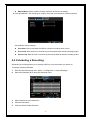
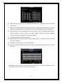
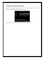
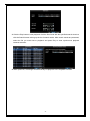
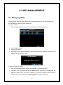
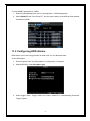
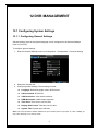
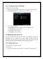
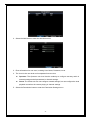
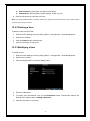
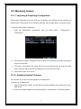
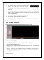
1
RD8504C H.264 LAN DVR User Manual Version 1.0.1 1 Preventive and Cautionary Tips Before connecting and operating your DVR, please be advised of the following tips: • Ensure unit is installed in a well-ventilated, dust-free environment. • Unit is designed for indoor use only. • Keep all liquids away from the DVR. • Ensure environmental conditions meet factory specifications. • Ensure unit is properly secured to a rack or shelf. Major shocks or jolts to the unit as a result of dropping it may cause damage to the sensitive electronics within the unit. • Power down the unit before connecting and disconnecting accessories and peripherals. 2 TABLE OF CONTENTS 1 2 3 4 5 PRODUCTION 6 1.1. Product Key Features 6 1.2. Operating Your DVR 8 1.3. Rear Panel Diagram 11 GETTING STARTED 12 LIVE VIEW 14 3.1. Watching a Live View 14 3.1.1. Understanding Live Preview Icons 14 3.1.2. Operating the Live Preview 14 3.1.3. Using the Mouse in Live Preview 15 3.1.4. Using Digital Zoom 15 3.2. Configuring Live Preview Displays 16 RECORD SETTINGS 17 4.1. Initializing Record Settings 17 4.2. Scheduling a Recording 18 4.3. Starting a Manual Recording 20 PLAYBACK 21 5.1. Understanding the Playback Interface 21 5.2. Playing Back 21 6 BACKUP 23 7 ALARM SETTINGS 25 7.1 Configuring Alarms 25 7.1.1 Setting up Motion Detection 25 7.1.2 Setting up Sensor Alarms 26 7.1.3 Triggering Alarm Outputs Manually 29 7.1.4 Detecting Video Loss 30 7.1.5 Detecting Video Tampering 31 7.2 Set up Exception 32 7.2.1 Setting Exception 32 7.2.2 Understanding Exception Trigger Options 33 3 8 NETWORK SETTINGS 34 8.1 Configuring Basic Settings 34 8.1.1 Static 34 8.1.2 DHCP 34 8.1.3 PPPoE 35 8.2 Configuring Advanced Settings 35 8.2.1 DDNS 35 8.2.2 NTP 36 8.2.3 E-mail Settings 37 8.2.4 FTP Settings 38 8.2.5 IP Filter 39 8.2.6 UPNP 40 PTZ CONTROLS 41 9.1 Navigating PTZ Menus 41 9.2 Configuring PTZ Settings 41 9.3 Setting PTZ Presets, Patrols & Patterns 42 9.3.1 Understanding PTZ Controls 42 9.3.2 Customizing Presets 43 9.3.3 Customizing Patrols 43 9.3.4 Customizing Patterns 45 9 10 CAMERA MANAGEMENT 47 10.1 Configuring OSD Settings 47 10.2 Setting up Privacy Mask 47 10.3 Adjusting Display Settings 48 11 HDD MANAGEMENT 50 11.1 Managing HDDs 50 11.2 Configuring HDD Alarms 51 12 DVR MANAGEMENT 52 12.1 Configuring System Settings 52 12.1.1 Configuring General Settings 52 12.1.2 Configuring Advanced Settings 53 12.2 Managing User Accounts 53 12.2.1 Adding a New User 53 12.2.2 Deleting a User 56 12.2.3 Modifying a User 56 12.3 Managing System 57 12.3.1 Importing & Exporting Configuration 57 12.3.2 Updating System Firmware 57 12.3.3 Restoring Default Settings 58 12.3.4 Viewing System Information 58 4 12.3.5 13 Viewing System Logs 59 REMOTE SURVEILLANCE 61 13.1. Setup ActiveX Plug-In 61 13.2. Remote Live View 63 13.3. Remote Playback 64 13.4. Setup 65 14 APPENDIX 66 14.1. Glossary 66 14.2. FAQ 67 5 1 PRODUCTION Thank you for your purchase of 5400C series Digital Video Recorder (DVR). To get the most out of your DVR, please read through this User Manual thoroughly. The 5400C series DVR is a new generation product. Built on an embedded platform and combining the latest in advanced H.264 video encoding and decoding technologies, the 5400C series DVR contains the perfect combination of rock-solid reliability and high performance. 1.1. Product Key Features Compression Support PAL/NTSC video input. Adopt H.264 video compression standard. Each analog channel supports dual stream. Main stream supports D1/CIF resolution and sub stream supports CIF/QCIF resolution. Video encoding parameters of each channel can be set separately, including resolution, frame rate, bit rate, image quality. Supports both composite stream and video only stream. Audio and video streams are strictly simultaneous. Monitoring Support VGA and CVBS video output. High definition VGA display support up to 1280*1024. Supports 1/4/9 screen live view. Support live view group switch, manual switch and automatic cycle, the interval of automatic cycle can be adjusted. Supports digital zoom on live view. Supports motion detection, view tampering alert and video loss alert. Supports privacy mask. Supports PTZ preset, patrol and pattern. 6 HDD Management Supports 1 SATA HDD up to 2TB capacity. Supports S.M.A.R.T. technology. Use pre-allocating hard disk management technology, and no disk fragments. Recording and Playback Supports cycle and non-cycle recording mode. Supports multiple recording types, including manual, continuous, alarm, motion, motion or alarm and motion & alarm recording, etc. Supports 8 recording time periods with separate recording types. Supports Pre-record and Post-record time for alarm and motion detection, and pre-record time for schedule and manual recording. Supports video data search and playback by channel number, recording type, time, event, etc. Supports pause, rewind, play fast, play slow, skip forward, and skip backward when layback, locating in progress bar by dragging the mouse. Backup Supports USB device and network backup. Alarm and Exception Supports alarm in/out arming schedule setting. Supports various alarm input such as hard disk full, network break, IP conflicted and hard disk error. Supports various alarm response such as camera recording, relay alarm out, on screen warning, audible warning, send email, etc. Network Supports 10/100 adaptive network interface. Supports TCP/IP protocols, PPPoE, DHCP, DNS, DDNS, NTP, UPnP etc. Supports remote search, playback and download video files. Supports remote configuration. Supports remote manual recording Supports remote manual alarm output control. Supports image capturing. 7 Supports remote PTZ control. Others Supports front panel, mouse, IR control operation. Supports multi-level user management, each user can have individual DVR access rights. Powerful DVR log, including operation, alarm, information and exception log. Supports remote manual alarm output control. 1.2. Operating Your DVR There are numerous ways to navigate and operate your DVR. You may use the Front Panel Controls, the included IR (Infra-Red) Remote, a Mouse and the Soft Keyboard. Using the Front Panel Controls The controls on the front panel include: 1. Power Button: Powers DVR on/off. 2. MENU/OKEXIT Button: In preview mode, user press the MENU/OK button will enter the main menu (after successful login): In the main menu mode, user press the MENU/OK button will confirm the selection. 3. DIRECTION Buttons & ESC: The DIRECTION buttons are used to navigate between different fields and items in menus. In Preview mode, these buttons can be used to cycle through channels. ESC button is used to exit the menu. 4. IR Receiver: Receiver for IR remote. 5. Status Indicators: Status indicators for different features of the DVR. POWER: POWER indicator turn on when DVR is power on. REC: REC indicator turns on when DVR is recording. ALARM: ALARM indicator turns on when a sensor alarm is detected. 8 Using remote control To use the remote control: 1. STANDBY: Press to turn standby mode ON/OFF. 2. Playback controls: : Increase rewind speed 2X, 4X, 8X; : Press to start playback; : Press to increase fast-forward speed 2X, 4X, 8X; : Press to slow-down playback by 1/2, 1/4, 1/8; : Press to pause, then press again to play single frame; 3. MENU: Opens the main menu. 4. Navigation/OK: : Move cursor in menus up; : Move cursor in menus right; : Move cursor in menus left; : Move cursor in menus down; OK: In menus, press to confirm selections; 5. Mode: Press to switch between quad and split-screen displays. 6. Number/Channel buttons: While in menus, press buttons 0~9 to enter values; during live viewing, press to view channels in full-screen. 7. ALARM: Clear alarm output. 8. SWITCH: Switch video output. 9. RECORD: Press to start manual recording. 10. STOP: Press to stop manual recording. 11. +/ - : In menus, press to adjust values. 12. PTZ: Press to open the PTZ control window. 13. EXIT: Close menu windows. 14. MUTE: Turn on / off audio output. 15. LOGIN / LOCK: If password has been enabled in the setup menu, press to open the user password login screen. 9 Using a USB Mouse A regular 3-button (Left/Right/Scroll-wheel) USB mouse can also be used with this DVR. To use a USB mouse: 1. Plug USB mouse into one of the USB ports on the front panel of the DVR. 2. The mouse should automatically be detected. If in a rare case that the mouse is not detected, please refer to the recommended device list from your provider. The buttons on the mouse corresponds to: 1. Left Button: Single-Click: Select a component of a menu, such as a button or an input field. This is similar to pressing the ENTER button on the remote/front panel controls. Double-Click: Switch between single screen and multi-screen mode in Preview/ Playback mode. Click and Drag: Clicking and dragging the Left mouse button can be used to control the digital zoom area. It can also be used to setup the alarm areas. 2. Right Button: Single-Click: Shows pop-up menu. 3. Scroll-Wheel: Scroll Up: In Menu mode, it will move the selection to the previous item. Scroll Down: In Menu mode, it will move the selection to the next item. Using the Soft Keyboard When a mouse is used to perform task on the DVR, clicking on a text input field will bring up the Soft Keyboard. The buttons on the soft keyboard represents: Lowercase: Designates lowercase input is being used. Uppercase: Designates uppercase input is being used. Backspace: Delete the character in front of the cursor. Space: Input spaces between letters. 10 Enter: Confirm selection. ESC: Exit out of Soft Keyboard. 1.3. Rear Panel Diagram No. Item Description 1 VIDEO IN BNC connectors for analog video input. 2 VIDEO OUT BNC connector for analog video output. 3 AUDIO IN Connector for 4 channels audio input 4 AUDIO OUT Connector for 1 channel audio output 5 VGA OUTPUT DB9 connector for VGA output. Display local video output and menu. 6 LAN interface Connector for LAN (Local Area Network). 7 USB interface Connector for USB device. 8 POWER SWITCH Power switch 9 RS485 PTZ control port 10 DC POWER IN 12V DC power input 11 2 GETTING STARTED 2.1 Starting and Shutting Down Your DVR Proper startup and shutdown procedures are crucial to expanding the life of your DVR. To startup your DVR: 1. Ensure the power supply is plugged into an electrical outlet. It is HIGHLY recommended that an Uninterruptible Power Supply (UPS) be used in conjunction with the unit. The Power indicator LED on the front panel should turn on, indicating the unit is receiving power. 2. Press the POWER switch on the rear panel. The Power indicator LED should turn on. The unit will begin to start. There are two proper ways to shutdown the DVR. To shutdown the DVR: • OPTION 1: Standard Shutdown 1. Enter the Shutdown menu, shown in Figure 1 by clicking on Menu > Shutdown. 2. Select the Shutdown button. 3. Click the OK button. 4. Press the POWER switch on the rear panel to safely shutting down the system. • OPTION 2: Manual Shutdown 1. Press and hold the STANDBY button for 3 seconds. 12 2. Press the POWER switch on the rear panel to safely shutting down the system. 2.2 Rebooting and Locking Your DVR While in the Shutdown menu, you may also reboot or lock your DVR. Locking your DVR will return you to the Live Preview mode, which will require an user name and password to exit out of it. The Reboot button will reboot your DVR. To reboot or lock your DVR: 1. Enter the Shutdown menu by clicking Menu > Shutdown. 2. Select the Lock button to lock the DVR or the Reboot button to reboot the DVR. 13 3 LIVE VIEW 3.1. Watching a Live View The Live Preview mode is automatically started after the DVR boots up. It is also at the very top of the menu hierarchy, thus hitting the ESC multiple times (depending on which menu you’re on) will bring you to the Live Preview mode. 3.1.1. Understanding Live Preview Icons There are multiple icons on each display in Live Preview mode to indicate different camera status. These icons include: Motion Detection Icon: Indicates motion detection. Video Tamper Icon: Indicates video tampering. Record Icon: Indicates the current channel is recording. Audio Icon: Indicates the current channel is in audio output. Alarm Icon: Indicate there is an alarm or exception. 3.1.2. Operating the Live Preview In Live Preview mode, you can: 1. Display Single Camera: Using Front Panel/Remote: Use Alphanumeric buttons. Using Mouse: Select Single Camera in right-click menu.. 2. Preview Layout Switch: Select Multi-Camera in right-click menu. 3. Manual Switch: Using Front Panel/ Remote: To move to the previous screen, click the Left direction button. To move to the next screen, click the Right direction button. Using Mouse: Select Next screen in right-click menu. 5. Auto Switch: Select Start Tour in right-click menu. 14 6. Digital Zoom: Select Digital Zoom in right-click menu. 3.1.3. Using the Mouse in Live Preview Many features of the Live Preview can be quickly accessed by clicking the right-button of the mouse. Single Camera: Switch to a full screen display of the selected camera. Camera can be selected from a drop down list. Multi-Camera: Switch between different displays layout options. Layout options can be selected from a drop down list. PIP: Picture in picture. To select this, you will have 2 cameras in 1 channel. Next Screen: When displaying less than the maximum number of cameras in Live Preview, clicking this feature will switch to the next set of displays. Playback: Enter into Playback mode. PTZ: Enter PTZ Control mode. Digital Zoom: Enter Digital Zoom interface. Menu: Enter Main menu. Start Tour: Enable sequencing in Live Preview mode. Note: The dwell time of the preview configuration should be set before using Start Tour. 3.1.4. Using Digital Zoom To use digital Zoom in Live Preview mode: 15 1. Right-click using the mouse in Live Preview mode. 2. Select Digital Zoom from Mouse menu. 3. Left-click and drag the red box to the desired area for zoom. The zoomed image will be magnified to full screen. : To enlarge the picture 2 times for each click. 6 times at most; : To shrink the enlarged picture till normal one; : To enlarge the selected area to full screen; : To turn the picture into normal size; : Exit. 3.2. Configuring Live Preview Displays Live Preview displays can be customized to your own needs. These settings can be accessed by entering the Display Settings menu. To access the Display Settings menu: 1. Click the Menu button. 2. Click the Configuration icon. 3. Click the Display Settings icon. The settings available in this menu include: Dwell Time: The time in seconds to dwell between switching of channels when Start Tour is selected in Live Preview. Audio: Enables/disable audio output for the selected video output. Border Adjustment: To adjust the border of video output. 16 4 Record Settings There are multiple ways to setup your DVR for recording. They include setting up a recording schedule, triggering a recording by motion detection and/or a sensor alarm, and manually starting the recording. 4.1. Initializing Record Settings Before setting your DVR up for recording, certain settings should be configured first. The steps to configuring these settings are: 1. You should initialize the HDD through HDD management before proceeding. 2. Navigate to Menu > Configuration > Record Settings. You will be taken to the Record Settings menu. 3. Select the camera you would to configure the settings for. 4. Configure settings for: Encoding Parameters: Select main stream or sub stream. Record Audio: Select to record audio of the camera. Resolution: The resolution is fixed as 4CIF for main stream, CIF for sub stream. BitRate Type: Select either Variable or Invariable bit rate. Video Quality: Select the quality to record cameras when the Bitrates type is selected as Variable. Otherwise, it can't be selected. Frame Rate: Select recordings frame rate. 17 Max Bit Rate: Select or define custom maximum bit rate for recordings. 5. Click ADVANCED. This will bring up another menu with more advance recording options. Set additional record settings: Overwrite: Sets to overwrite the HDD to continue recording when it is full. Pre-record: Sets the time in seconds to pre-record before the actual recording begins. Post-record: Sets the time in seconds to post-record after the actual recording ended. 4.2. Scheduling a Recording Scheduling a recording allows you to setup the DVR to only record when you want it to. To setup a recording schedule: 1. Enter the Record Settings menu (Menu > Configuration > Record Settings). 2. Select the Schedule tab to open the Schedule menu. 3. Select Camera to edit schedule for. 4. Click the Edit button. 5. Click and check Enable Schedule. 18 6. Select the day you would like to setup the schedule for or select All Week to record the entire week. 7. Select to record the entire day by clicking All Day or at different time periods. Up to 8 time periods can be scheduled. It is important to note that time periods cannot be overlapped. 8. Select recording Type. Recording type can be based on time and triggered by schedule, motion detection, motion or alarm and alarm. Motion detected and alarm triggered recordings are further explained in Configuring Alarms. 9. Click the OK button to finish configuration. 10. Repeat steps 3-9 for other cameras or copy settings from one schedule to the next under the Copy To section. 11. Click OK to finish and save the schedule settings. 12. If all the cameras recording settings are the same, please select All under Copy To section as shown: Note: Event encoding parameters will take effect when motion detection or alarm happens. Normal encoding parameters will take effect when there are no events happening. 19 4.3. Starting a Manual Recording A manual recording can be started at any time. To start a manual recording: Start manual recording by selecting Start or Stop for the cameras desired. Note: Only when the scheduled recordings are off can user manually start or stop recording. 20 5 PLAYBACK 5.1. Understanding the Playback Interface There are various controls on the Playback interface that makes viewing recordings more efficient. : Audio on/off: Select to open or close the audio; : Fast backwards: Select to rewind recording files at the speed of x2, x4, x8; : Play; Select to return to normal speed to playback files; : Pause / Single Frame: Select to pause or play in single frame; : Fast Forwards: Select to playback the recording files forward at the speed of x2, x4, x8; : Slow Forwards: Select to playback the recording files forward at the speed of x1/2, 1/4, 1/8; : Hide; Select to hide the playback control panel; : Exit; Select to exit playback; : Playback progress: To drag the playback progress to a desired time; : Recording Type: indicate the recording types during the period. Note: Blue Record Time Line designates schedule/manual recording while red one shows event recording. 5.2. Playing Back To playback files from a video search: 1. Enter into the Video Search menu by clicking Menu > Video Search. 2. Select cameras to search, video type (All, Manual, Schedule, Motion, Alarm, Motion or Alarm) and the start/end time. 21 3. Click the Play button to start playback of all the files found with the specified search criteria or click the Search button to bring up the list of search results. After search results are presented, select the file you would like to playback and press Play to enter synchronous playback cameras selection. 4. When press OK, recordings will automatically be playback in the Playback interface. 22 6 BACKUP Recorded files can be backed up to various devices, such as USB flash drives, or USB HDD. To export recorded files: 1. Enter the record backup menu by clicking Menu >Record Backup. 2. Select desired parameters to search for files to backup. 3. Press the Backup button. This will take you to the Search Results menu. 4. Select the files to export. You may also click the Play button to verify that these files are indeed the ones you would like to export. 5. The size of the currently selected files is displayed in the lower-left corner of the window. Select the Next button to enter the Backup menu. 6. Select device to export to from drop-down list. If backup device is not recognized: Click the Refresh button. Reconnect device. 23 Check for compatibility from vendor. 7. Delete: Delete a file from the backup device 8. Format: Format the backup device. 9. Click Start to begin backup process. 24 7 ALARM SETTINGS 7.1 Configuring Alarms 7.1.1 Setting up Motion Detection Set up properly, using motion detected recording will increase the number of days your DVR is able to record. It will only record relevant events rather than recording everything, making searching for an event easier. To set up motion detection: 1. Enter Camera Settings: Enter the Camera Settings interface by navigating to Menu > Configuration > Camera Settings. Select channel to configure motion detection on. 2. Select the Advanced tab to open up the Advanced Camera Settings menu. 3. Check the checkbox next to Video Motion Detection, and enable Motion Detection as 4. Click the Area Settings button to enter the Motion Detection area and Sensitivity . configuration interface. 5. The Motion Detection area, allows you to mask out areas where you would like motion to be detected in. The maximum area is the whole screen. You can left click mouse, hold and drag it to mask the Motion Detection area. 25 6. Right click mouse to set the Motion Detection Sensitivity. 7. Right click mouse to select Save to return to the Camera Settings menu. 8. Click the Handle button to open the Handle menu. Select the Triggered Camera tab. 9. Select cameras to trigger for recording when motion is detected by checking the checkboxes under the desired cameras. 10. Select Schedule tab to set arm time, 8 periods can be set. 11. Click OK to complete motion settings for the selected camera. You may now add a schedule to start recording when motion is detected (See Scheduling a Recording). 7.1.2 Setting up Sensor Alarms Recordings can also be triggered from an external sensor alarm device. To setup sensor alarms: Enter into the Alarm Settings menu by navigating to Menu>Configuration>Alarm Settings. 26 1. Select the Alarm Input and click the Set button. This will open the Alarm Input Setting menu. 2. Set the alarm input type. The options available are Normally Opened (N.O.) and Normally Closed (N.C.). 3. Select the checkbox next to Handle Alarm In as and click the Handle button to enter the Alarm Input Handle menu. 4. Select the Triggered Camera tab. 5. Select cameras to trigger for recording when alarm occurs by checking the checkboxes under the desired cameras. 27 6. Click the OK button to complete setup. You may now add a schedule to start recording when an alarm is triggered (See Scheduling a Recording). Alarm outputs may also be configured in the Alarm Management menu. To set up Alarm Output: 1. Select the Alarm Output tab. This will bring up the Alarm Output interface. 2. Select the output you would like to configure and click the Set button. This will bring up the settings page for the selected channel. 28 3. Configure the settings for selected output. 4. Select OK to save and exit. Note: If the Hold For option is selected as Manually Stop, the alarm will only stop when you manually stop it (See Triggering Alarm Outputs Manually). 7.1.3 Triggering Alarm Outputs Manually To trigger alarm outputs manually: 1. Enter the Manual Alarm menu by clicking Menu > Manual Alarm. 2. In the Manual Alarm menu, you may: 3. Trigger: Select an alarm from the list and click Trigger to trigger its output. Trigger All: Trigger all alarm outputs at once. Clear All: Stop all alarm outputs at once. Select OK to return to the previous menu. 29 7.1.4 Detecting Video Loss To setup video loss detection: 1. Enter Camera Management/Settings menu by clicking Menu > Configuration > Camera Settings. 2. Select the Advanced tab. 3. Check the Video Loss Detection checkbox to enable feature. 4. Click the Handle button to enter the Handle menu. 5. Select the Handle tab to configure exceptions handling. Exception trigger options are further explained in the next section (See Understanding Exception Trigger Options). 6. Select the Schedule tab. Set the schedule of when you want video loss detection to be enabled. Schedule can be set for all week or any day of the week with up to 8 time periods per day. 30 7. Click the Apply button to finish. 8. Repeat above for other channels. If all channel and all week are the same settings, please select Copy To All Week and Copy to All channel in Advanced tab. 7.1.5 Detecting Video Tampering To setup video tempering detection: 1. Enter Camera Settings menu by clicking Menu > Configuration > Camera Settings. 2. Select the Advanced tab and select camera to configure tamper detection. 3. Select the Tamper Detection checkbox. 4. Select the sensitivity of the camera tamper detection, HIGH, MEDIUM, and LOW. 5. Click the Handle button to enter the Handle menu. 6. Select the Schedule tab. Set the schedule of when you want video tamper detection to be enabled. Schedule can be set for all week or any day of the week with up to 8 time periods per day. 31 7. Select the Handle tab to configure exceptions handling. Exception trigger options are further explained in the next section (See Understanding Exception Trigger Options). 8. Click the Apply button to finish. 9. Repeat above for other channels. If all channel and all week are the same settings, please select Copy To All Week and Copy to All channel in Advanced tab. 7.2 Set up Exception 7.2.1 Setting Exception Setting exceptions allow the DVR to alert you when irregular events occur. These events include: HDD Full: All installed HDD are full. HDD Error: Errors occurred during writing of the HDD, no HDD installed or HDD had failed to initialize. Net Disconnected: Disconnected network cable. 32 IP Conflict: Conflict in IP address setting. To set exceptions: 1. Enter the Exception menu by clicking Menu > Configuration >Exception. 2. Select the exception to configure under Exception Type. 3. Select triggering options. Trigger options are further explained in the next section (See Understanding Exception Trigger Options). 7.2.2 Understanding Exception Trigger Options When setting up exception handlers for such features as motion detection and sensor alarms, you may select triggering options to alert you of these exceptions. The triggering options that you may select include: Audio Warning: Trigger an audible beep when exception is detected. Trigger Alarm Output: Trigger an alarm output when exception is detected. Alarm output can be configured by following the steps listed in Setting Up Sensor Alarms. Send Email: Sending email when exception is detected. Sending email can be configured by following the steps listed in Configuring E-mail Settings. 33 8 NETWORK SETTINGS 8.1 Configuring Basic Settings To configure basic network settings: Enter the Network Settings menu by clicking Menu > Configuration > Network Settings. 8.1.1 Static Select Static under General tab. Fill in IP Address, Subnet Mask, Default Gateway, Preferred DNS Server, Server Port, HTTP Port. Note: The IP address can not be conflict with that of any other device. Every port, including the SERVER PORT, HTTP PORT must be forwarded in the router. SEVER PORT is used for the CMS and Phone Surveillance. To have access via internet through WAN, please be sure that your DNS SERVER has been set correctly. 8.1.2 DHCP Select DHCP in Network Access, and then click OK. Then please check the DHCP status in Network Status tab. 34 Note: when you select DHCP, the IP Address, Subnet Mask and Gateway will be obtained automatically. Please check the DVR IP in the Network Status. 8.1.3 PPPoE Select PPPoE in Network Access, Enter User Name, Password, and Confirm Password for PPPoE access. PPPoE credentials can be obtained from your network administrator. Once the setup is completed, your DVR will automatically dial-up into your network after rebooting. Please check the PPPoE status in Network Status tab. Note: When using PPPoE, there is no need to forward the ports, it will forward the ports automatically. 8.2 Configuring Advanced Settings 8.2.1 DDNS To setup DDNS: 1. Enter the Network Settings menu by clicking Menu > Configuration > Network Settings. 2. Select the Advanced tab. 35 3. Select the Set button next to DDNS to enter the DDNS settings menu. 4. Check the DDNS checkbox to enable feature. 5. Select DDNS Type. Support 3322 and DynDNS. 3322: Enter Device Domain name for 3322 (i.e. test.3322.org) obtained from the website www.3322.org. Lastly, enter the User Name and Password registered in the 3322 network. DynDNS: Enter Device Domain Name (i.e. test.dyndns.org) obtained from the website www.dyndns.com. Lastly, enter the User Name and Password registered in the DynDNS network. 8.2.2 NTP A Network Time Protocol (NTP) Server may also be setup on your DVR to keep the date and time current and accurate. To setup an NTP server: 36 1. Enter the Network Settings menu by clicking Menu > Configuration > Network Settings. 2. Select the Advanced tab. 3. Select the Set button next to NTP to enter the NTP settings menu. 4. Check the NTP checkbox to enable feature. 5. Set NTP settings: • NTP Server: IP address of NTP server. • NTP Port: Port of NTP server. 6. Click Sync to synchronize the time with NTP server. 7. Click OK to save and exit menu. Note: If the DVR is used on a public network, you should use a NTP server that has a time synchronization function, such as the server at the National Time Center (IP Address: 210.72.145.44). If the DVR is setup in a more customized network, NTP software can be used to establish a NTP server used for time synchronization. 8.2.3 E-mail Settings To configure E-mail settings: 1. Enter the Network Settings menu by clicking Menu > Configuration > Network Settings. 2. Select the Advanced tab. 3. Click the Set button next to E-mail to enter the E-mail menu. 37 4. Enter e-mail settings. 5. Click the Send Email button to test e-mail settings. 6. Select Attached Picture if you want to send email with alarm images, the interval of two adjacent pictures is 30s. You can also set SMTP port and enable SSL here. 7. Click the OK button to save and exit the E-mail menu. Note: It is recommended that the e-mail settings be tested after they are entered. This can be accomplished by clicking the Send Email button in the E-mail menu. 8.2.4 FTP Settings FTP is used to upload recording streaming to your FTP server. You can set up an uploading schedule, which triggered by time, motion detection, or/and alarm. To configure FTP settings: 1. Enter the Network Settings menu by clicking Menu > Configuration > Network Settings. 2. Select the Advanced tab. 3. Click the Set button next to FTP to enter the FTP menu. 4. Configure FTP settings. It includes FTP server information and uploading schedule. 38 There are multiple icons on each display in Live Preview mode to indicate FTP uploading status when FTP uploading is triggered. These icons include: This icon indicates the DVR is uploading the streaming of this channel, and it work very well. This icon indicates the DVR is uploading the streaming of this channel, but some streaming packets are lost. You should check the network status and FTP server status. This icon indicates the DVR is trying to upload the streaming of this channel, but it failed. You should check whether the FTP configuration is correct. Also you should check the network status and FTP server status. 8.2.5 IP Filter IP filter is used to manage the remote access to your DVR. The management is based on the IP address of remote visitor. 1. White List: If you select the white list, only the listed IP address can connect your DVR. While 2. Black List: If you select black list, the listed IP address can not connect your DVR. 39 3. None: If you want to disable this function, you can select NONE for restricted type. And any IP can have access to the DVR. 8.2.6 UPNP UPnP Forum is an industry initiative designed to enable simple and robust connectivity among consumer electronics, intelligent appliances and mobile devices from many different vendors. In our DVR, UPNP is used to automatically map the HTTP port and server port in your router. To configure UPNP settings: 1. First of all, enable the UPNP function in your Router. If your router doesn’t support UPNP, this function can’t work. 2. Enter the Network Settings menu by clicking Menu > Configuration > Network Settings, select the Advanced tab, and enable UPNP. By default, the UPNP is enabled. 40 9 PTZ CONTROLS 9.1 Navigating PTZ Menus PTZ menus can be navigated through mouse. For quick access to certain PTZ settings, right clicking with the mouse in a display while in PTZ control mode will bring up the PTZ settings menu. The items that can be found on this menu include: Camera: Select a PTZ camera. Call Preset: Call a PTZ preset. Call Patrol: Call a PTZ sequence. Call Pattern: Call a PTZ pattern. Preset: Enter PTZ preset configuration menu. Patrol: Enter PTZ patrol configuration menu. Pattern: Enter PTZ pattern configuration menu. PTZ Menu: Enter the menu of PTZ. PTZ Settings: Enter PTZ setting menu. 9.2 Configuring PTZ Settings Settings for a PTZ camera must be configured before it can be used. Before proceeding, verify that the PTZ and RS-485 of the DVR are connected properly. 41 To configure PTZ settings: 1. Enter the PTZ Settings menu by clicking Menu > Configuration > PTZ Settings. 2. Select channel where PTZ camera is installed next to Camera label. 3. Enter PTZ settings according to the camera. 4. Click OK button to save and exit menu. 9.3 Setting PTZ Presets, Patrols & Patterns 9.3.1 Understanding PTZ Controls Before setting presets, patrols and patterns, it’s important to understand some of the features of the PTZ control panel, shown in Figure 3. The controls on the PTZ panel include: 1. Directional Pad/Auto-scan Buttons: Controls the movements and directions of the PTZ. Center button is also used to start auto-scan of PTZ. 2. Zoom: Used to zoom in and out with the PTZ. 3. Focus: Used to adjust the focus of the PTZ. 4. Iris: Used to open up or close the iris of the PTZ. 42 5. Speed: Adjusts the movement speed of the PTZ. 6. Light: Turns PTZ light (if applicable) on and off. 7. Wiper: Turns PTZ wiper (if applicable) on and off. 8. Zoom In: Instantly zooms PTZ in. 9. Center: Centers PTZ. 9.3.2 Customizing Presets Presets can be set to move your PTZ camera to a desired preset location at the click of a button. To setup and use custom PTZ presets: 1. Enter the PTZ Control interface, PTZ in the sub menu or the PTZ button on the front panel. 2. Select the Preset button to enter the Preset Management menu. 3. In the Preset menu, you may: Configure Preset: Use the PTZ control panel to adjust the position of the preset. Select a Preset number and click the Set button to save preset location. Clear Preset: Select a Preset number and click the Clear button to delete the preset. You may also select the Clear All button to delete all presets. Call Preset: Select a Preset and click the Call button. Note: Only valid presets can be called and deleted. 9.3.3 Customizing Patrols Patrols can be setup to move the PTZ to different key points and have it stay there for a set duration before moving on to the next point. The key points are defined by presets which can be set following the steps above in Customizing Presets. To set up and use PTZ patrols: 1. Enter the PTZ Control interface, shown in Figure 3 by clicking PTZ in the mouse menu or the PTZ button on the front panel. 43 2. Select the Patrol button to enter the Patrol Management menu. 3. In the Patrol Management menu, you may: Configure Patrol: Step1: Select a Patrol Number to set. Step2: Select valid presets (See Customizing Presets) and click the Set button to enter the Patrol configuration menu. A sequence should have at least 2 valid presets. Step3: Set the Preset Name, Duration, and Speed. The Key Point No. determines the order at which the PTZ will follow while cycling through the patrol. The Duration refers to the time span to stay at the corresponding key point. The Speed defines the rate at which the PTZ will move from one key point to the next. Step4: Click OK to return to Patrol Management menu and repeat steps 2-3 to configure other key points. Step5: After all key points have been configured, click OK to save and exit menu. Clear Patrol: Step1: Select a valid Patrol Number. Step2: Click the Clear button to delete patrol. 44 Call Patrol: Step1: Select a valid Patrol Number. Step2: Click the Start button to call the patrol, select the stop button to stop the patrol. 9.3.4 Customizing Patterns Patterns can be setup by recording the movement of the PTZ. To setup and use PTZ patterns: 1. Select the Pattern button to enter the Pattern Management menu. 2. Select a Pattern Number. 45 3. To record a new pattern, select the Run Record button to start recording of the movements of the PTZ. Use the PTZ control panel to move the PTZ. The PTZ movements will be recorded until the Stop Record button is clicked. 4. To run a pattern, click the Run Pattern button on a valid pattern. The PTZ will move according to the path that was defined until Stop Pattern is clicked. 5. Click OK to save and exit from menu. 46 10 CAMERA MANAGEMENT 10.1 Configuring OSD Settings On Screen Display (OSD) settings can be configured in the Camera Management menu. The OSD is shown in each display during Live Preview mode and includes the time and date as well as the camera name. To configure OSD settings: 1. Enter the Camera Management/Settings menu, by clicking Menu > Configuration > Camera Settings. 2. Select channel to setup OSD settings under Channel #. Click the Set button. 3. Configure desired OSD settings. 10.2 Setting up Privacy Mask You may setup privacy mask to mask off sensitive or private areas in the field of view of a camera. To setup privacy mask: 1. Enter the Camera Management/Settings menu, shown in Figure 1 by clicking Menu > Camera Settings. 47 2. Select channel to setup privacy mask under Channel #. Click the Set button. 3. Select the Advanced tab to enter the Advanced Camera Settings menu. 4. Check the Mask checkbox to enable feature. 5. Click the Area Settings button to enter Area Settings menu. 6. Setup mask area. Up to 4 areas can be set. 7. Select OK to save and exit mask setup. Note: Max. 4 areas can be set. 10.3 Adjusting Display Settings Display settings such as the brightness, contrast, saturation and hue can also be adjusted in the Camera Management menu. To adjust display settings: 1. Enter the Camera Management/Settings menu by clicking Menu > Configuration > Camera Settings. 2. Select channel to adjust display settings under Channel #. Click the Set button. Enter Camera Settings menu when click Camera icon.) 3. Select the Advanced tab to enter the Advanced Camera Settings menu. 4. Click the Set button next to the Image Settings label. 5. Adjust the display settings. Brightness, contrast, saturation and hue can be adjusted. The adjustments of display settings not only affect previewed images, but also recorded images. 48 49 11 HDD MANAGEMENT 11.1 Managing HDDs A newly installed hard disk drive (HDD) must be first initialize before it can be used with your DVR. Initializing the HDD will erase all data on it. To initialize a HDD: 1. Enter the HDD Management menu by clicking Menu > HDD Management. 2. Select HDD to initialize. 3. Click the Init button. 4. Select OK button to begin initialization. After the HDD has been initialized, the status of the HDD will change from No to Yes. To check the status of a HDD: 1. Enter the HDD Management menu by clicking Menu > HDD Management. 2. The status of your HDD is listed under the Status column. If the status is listed as Yes, the HDD is in working order. If the HDD is Uninitialized, you will need to initialize it before it can be used in your DVR. Please refer to Initializing HDDs for further instructions. 50 To view SMART information of a HDD: 1. Enter the HDD Management menu by clicking Menu > HDD Management. 2. Select S.M.A.R.T tab. From S.M.A.R.T, we can see the status of the HDD and the detailed information of HDD. 11.2 Configuring HDD Alarms HDD alarms can be set to trigger when an HDD is full or in an abnormal state. To set HDD alarms: 1. Enter Exception menu by clicking Menu > Configuration > Exception. 2. Select HDD Error under Exception Type. 3. Select trigger action. Trigger actions are further explained in Understanding Exception Trigger Options. 51 12 DVR MANAGEMENT 12.1 Configuring System Settings 12.1.1 Configuring General Settings General settings such as the system language can be configured in the General Settings menu of your DVR. To configure general settings: 1. Enter the General Settings menu by clicking Menu > Configuration > General Settings. 2. Select the General tab. 3. Configure general settings. These settings include: Language: Default language used in DVR menus. Video standard: NTSC/PAL. VGA Resolution: VGA output resolution. HDMI Resolution: HDMI output resolution. Time Zone: Time zone to use for DVR. Display Date Format: Format to use for date. System Time: System time and date. Note: If the video standard is different between the input (camera) and the output (the TV, VGA or HDMI), you may notice flickering in Live Preview mode. 52 12.1.2 Configuring Advanced Settings To configure more advanced settings: 1. Enter the General Settings menu by clicking Menu > Configuration > General Settings. 2. Click the More Settings tab; this will take you to the More Settings menu. 3. Configure settings, including: Enable Password: Enable or disable the password to operate the DVR. Device Name: Name to use for DVR. Device ID: The No. of the DVR. Device Name: The name of DVR. 12.2 Managing User Accounts By default, your DVR comes with one user account, the Administrator account. The Administrator user name is admin and the password is 12345. The default password for Administrator should be changed right away for security reasons. The Administrator has the authority to add, delete or configure parameters for many of the system functions. 12.2.1 Adding a New User You may add up to 10 new users to your DVR. To add new users: 1. Enter the User Settings menu by clicking Menu > Configuration > User Management. 53 2. Select the Add button to enter the Add User menu. 3. Enter information for new user, including User Name, Password, Level. 4. The Level is the user level and is separated into two tiers. Operator: The Operator user level has the authority to configure two-way audio in network settings and all parameters in channel settings. Guest: The Guest user can not configure network settings, but can configure the local playback as well as the remote playing in channel settings. 5. Select the Permission button to enter the Permission Settings menu. 54 6. Configure privileges for local settings under Configuration tab. The Configuration include: General Settings: Set the language, video standard, VGA resolution, HDMI, time zone, display date format and system time, etc. Camera Settings: Enable and disable analog channels. Record Settings: Set the record mode. Network Settings: Set the IP, DDNS, etc. PTZ Settings: Set the PTZ configuration. Alarm Settings: Set the alarm. Display Settings: Set the parameters for display. Exception: Set the exception warning. 7. Click on the Permission Settings tab. Remote Live View: Select and view live video over the network. Manual Record: Locally start and stop manual recording on any of the channels. Playback: Locally play recorded files that are on the DVR. PTZ Control: Locally control PTZ cameras. 55 Manual Alarm: Locally start and stop manual alarm. Maintenance: DVR upgrade, default settings, search log, etc. 8. Click the OK button to save and exit menu. Note: If you forget the password to your DVR, contact your supplier with the serial number of your DVR to obtain a secure code to reset your DVR. 12.2.2 Deleting a User To delete a user from the DVR: 1. Enter the User Settings menu by clicking Menu > Configuration > User Management. 2. Select user to delete. 3. Click the Delete button to delete user. 4. Click the OK button to exit menu. 12.2.3 Modifying a User To modify a user: 1. Enter the User Settings menu by clicking Menu > Configuration > User Management. 2. Select user to modify. 3. Click the Modify button to enter the Modify menu. 4. Edit user information. 5. To modify user permissions, click on the Permission button. Permissions settings are defined in the section above, Adding a New User. 6. Click the OK button to exit menu. 56 12.3 Managing System 12.3.1 Importing & Exporting Configuration Configuration information from your DVR can be exported to a USB device and imported into another DVR. This will allow you to efficiently setup the same configuration on numerous DVRs. To import or export DVR configuration: 1. Enter the Import/Export Configuration menu by clicking Menu > Maintenance > Configuration. 2. Click Export to export a configuration file to USB device. USB device must be connected at this point to the DVR. 3. To import a configuration file, select the file from the USB device and click the Import button. After the import process is completed, you must reboot the DVR. 4. Click Cancel to exit out of menu. 12.3.2 Updating System Firmware The firmware on your DVR can be updated via an USB device. To update via an USB device: 1. Connect USB device to DVR. The firmware file must be located in the root directory of your USB device. 2. Enter the Firmware Update menu by clicking Menu > Maintenance > Firmware Upgrade. 57 3. Select the firmware on the USB device. 4. Select Upgrade to begin the update process. 5. After the system firmware has been updated, reboot the DVR. Note: If the DVR fails to update, please contact your system supplier for further assistance. 12.3.3 Restoring Default Settings To restore default factory settings to your DVR: 1. Enter the Default Settings menu by clicking Menu > Maintenance > Default Settings. 2. Select OK to restore factory defaults. 12.3.4 Viewing System Information To view system information: 1. Enter into the Information menu by clicking Menu > Maintenance > System Information. 58 2. Select OK to exit to the previous screen. 12.3.5 Viewing System Logs Many events of your DVR are logged into the system logs. To access the system logs and search for these events: 1. Enter the Log Search menu by clicking Menu > Maintenance > Log Search. 2. Set search parameters. 3. Click the Search button to begin search. If logs matching the search criteria are found, it will be displayed. 59 4. Click Cancel to exit out of menu. 60 13 REMOTE SURVEILLANCE The system features a built-in browser-based software that allows you to access your system remotely over your local area network (LAN) or over the Internet using Internet Explorer. Install the software through the IE browser of OS and you operate the network remotely and conveniently. DVR supports C/S, B/S, and visit in LAN and WAN, also supports IP and domain name visiting. Note: To ensure PC's stable visiting of DVR, recommend Windows XP, Windows Vista,Windows 7 operation system, recommend browser as IE 6.0, IE 7.0. IE 8.0. 13.1. Setup ActiveX Plug-In With your system connected to your local area network, you can now log in to your system using Internet Explorer. To access the DVR by IE, you must setup an ActiveX control firstly. You can download this ActiveX plug-in from DVR or setup it from the attached CD. Setup ActiveX control from attached CD In the attached CD, enter the directory of Tools; double click the setup file (named as Plugin_Setup_Vx.x.x.x.exe). The setup wizard will instruct you to setup the IE control step by step. Download ActiveX control from DVR To download ActiveX control for your DVR: 1. Start Internet Explorer; Go to Tools / Internet Options; Click on the Security table, select the Trusted sites and click the Sites button. 2. In the Trusted sites page, input your DVR’s IP address or domain name (The default IP address of your DVR is 192.168.1.100), then click Add button to add your DVR’s sites into the trusted sites list. Then close this page. 3. In the Security page click the Default level and set the security level as Low. 4. In IE address bar, enter the IP address of your system (The default IP address of the DVR is 192.168.1.100). 61 5. You must install the ActiveX in order to access your system. Click the attention bar at the top of the main page and select Install ActiveX Control. DVR Net viewer will reset. 6. In the warning box click Install. The login page appears. Note: The process will last for several minutes. If you access the DVR from Internet, it will take more time. 62 13.2. Remote Live View Upon login, the Remote Surveillance main screen appears in your browser. By default, remote surveillance opens in Preview mode (split-screen). 1) Modes: Preview, Playback, and Setup. 2) Channel: Channel number appears in the left of the main screen. You can double click the channel number to open / close the preview of this channel. 3) PTZ Control: PTZ control for any connected PTZ cameras. To control a PTZ camera: Select the channel of the connected PTZ camera(s). Click the navigation arrows to pan and tilt the camera. 3. Click + /- to control zoom, focus, and iris. You can adjust the movement speed of the PTZ by dragging the scroll bar. 4) : Click this button to operate presets. You can add, delete and call the preset. Click this button to operate patrol. You can add, clean, start and set the patrol. Click this button to Instantly zooms PTZ Click this button to turn on/off the PTZ light (if applicable) Click this button to turn on/off the PTZ wiper (if applicable) Image Settings: Adjust the brightness, contrast, saturation and hue of the selected channel. 5) Functions: 63 1. Click this button you can record video of the selected channel directly to your PC. By default, recorded files are saved in C:\Downloadfile. You can modify the directory in Setup -> Local Setup page. 2. Click this button you can take a snapshot of the selected channels on the main display screen. By default, recorded files are saved in C:\Capture. You can modify the directory in Setup -> Local Setup page 3. Click this button you can switch to the previous channel(s). 4. Click this button you can switch to the next channel(s). 6) Display Modes: Click the icons to view channels in single-channel full-screen, quad, and split-screen configurations. 13.3. Remote Playback Use the Replay menu to search and playback recorded video on your system. Search the recording files 1) Click Playback at the top of the main screen. The main screen will be grey; 2) Select a channel to playback (Area 1) ; 3) Select the search condition: Start time, End time and recording file type, then click Search button (Area 2); 4) Seletct a recording file from the search result (Area 3) and then you can control this file, including Play, Pause, Speed-up, Slow-down, single frame, and also you can download this recording file to you PC (Area 4, 5, 6). Playback Control 64 Playback control bar: 1) Play / Pause. 2) Stop 3) Slow-down 4) Speed-up 5) Single frame forward 6) Snap shot 7) Download the recording file. The default 8) Mute / Unmute 9) Volume control 10) Play position scroll bar 13.4. Setup Click Setup at the top of the main screen, you can select local setup or remote setup from the pop-up menu. Local Setup In local setup page, you can setup the directory for recording live streaming, backup files, snap shot and config file. Remote Setup Use the remote setup to configure the settings of your DVR from network. 65 14 APPENDIX 14.1. Glossary 1. Dual Stream: Dual stream is a technology used to record high resolution video locally while transmitting a lower resolution stream over the network. The two streams are generated by the DVR, with the main stream having a maximum resolution of 4CIF and the sub-stream having a maximum resolution of CIF. 2. DVR: Acronym for Digital Video Recorder. A DVR is device that is able to accept video signals from analog cameras, compress the signal and store it on its hard drives. 3. HDD: Acronym for Hard Disk Drive. A storage medium which stores digitally encoded data on platters with magnetic surfaces. 4. DHCP: Dynamic Host Configuration Protocol (DHCP) is a network application protocol used by devices (DHCP clients) to obtain configuration information for operation in an Internet Protocol network. 5. HTTP: Acronym for Hypertext Transfer Protocol. A protocol to transfer hypertext request and information between servers and browsers over a network 6. DHCP: PPPoE, Point-to-Point Protocol over Ethernet, is a network protocol for encapsulating Point-to-Point Protocol (PPP) frames inside Ethernet frames. It is used mainly with ADSL services where individual users connect to the ADSL transceiver (modem) over Ethernet and in plain Metro Ethernet networks. 7. DDNS: Dynamic DNS is a method, protocol, or network service that provides the capability for a networked device, such as a router or computer system using the Internet Protocol Suite, to notify a domain name server to change, in real time (ad-hoc) the active DNS configuration of its configured hostnames, addresses or other information stored in DNS. 8. NTP: Acronym for Network Time Protocol. A protocol designed to synchronize the clocks of computers over a network. 9. NTSC: Acronym for National Television System Committee. NTSC is an analog television standard used in such countries as the United States and Japan. Each frame of an NTSC signal contains 525 scan lines at 60Hz. 10. PAL: Acronym for Phase Alternating Line. PAL is also another video standard used in broadcast televisions systems in large parts of the world. PAL signal contains 625 scan lines at 50Hz. 11. PTZ: Acronym for Pan, Tilt, Zoom. PTZ cameras are motor driven systems that allow the camera to pan left and right, tilt up and down and zoom in and out. 66 12. USB: Acronym for Universal Serial Bus. USB is a plug-and-play serial bus standard to interface devices to a host computer. 14.2. FAQ • Why does the DVR seem unresponsive when operating with the IR remote control? If your DVR seem unresponsive when using the IR remote and you have read through the section Using the IR Remote Control, please check: 1. Check that the batteries are installed correctly in the remote, making sure that the polarities of the batteries are not reversed. 2. Make sure the batteries are fresh and are not out of power. 3. Make sure the remote has not been tampered with. 4. Check around and make sure there are no fluorescent lamps in use. • Why does the PTZ seem unresponsive? If the PTZ seem unresponsive, please check: 1. Check that the RS-485 cable is properly connected. 2. Check that the dome decoder type is correct. 3. Check that the dome decoder speed configuration is correct. 4. Check that the dome decoder address bit configuration is correct. 5. Check to make sure that the main board RS-485 interface is not broken. • Why is there no video recorded after setting the motion detection? If there are no recorded video after setting the motion detection, please check: 1. Check that the recording schedule is setup correctly by following the steps listed in Scheduling a Recording. 2. Check that the motion detection area is configured correctly (See Setting Up Motion Detection). 3. Make sure that channels are being triggered for motion detection (See Setting Up Motion Detection). • Why doesn’t the DVR detect my USB export device for exporting recorded files? There’s a chance that the DVR and your USB device is not compatible. Please refer to our company’s website to view a list of compatible devices. http://www.global-export-import.eu 67 68