1
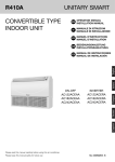
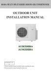
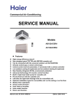
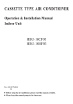
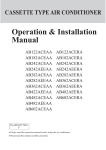
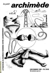
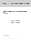
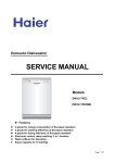
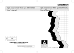
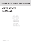
CONVERTIBLE TYPE AIR CONDITIONER
Operation & Installation
Manual
AC142ACERA
AC182ACERA
AC242ACERA
No. 0010576952
A
Please read this operation manual before using the air conditioner.
Please keep this manual carefully and safely.
Contents
Cautions ............................................................................... 1-2
Safety Precautions .................................................................. 3
Name of Parts.......................................................................... 4
Cleaning and Care .................................................................... 5
Operation Tips .......................................................................... 6
Installation................................................................................ 7
Installation Procedures ...................................................... 8-19
Trouble Shooting ...................................................... 20-22
Cautions
Disposal of the old air conditioner
Consult your local authorities for the name and
address of the waste materials collecting centers
and waste paper disposal services nearest to
your house.
Before disposing an old air conditioner that
goes out of use, please make sure it's
inoperative and safe. Unplug the air
conditioner in order to avoid the risk of
child entrapment.
It must be noticed that air conditioner
system contains refrigerants, which require
specialized waste disposal. The valuable
materials contained in a air conditioner can
be recycled. Contact your local waste
disposal center for proper disposal of an
old air conditioner and contact your local
authority or your dealer if you have any
question. Please ensure that the pipework
of your air conditioner does not get
damaged prior to being picked up by the
relevant waste disposal center, and
contribute to environmental awareness by
insisting on an appropriate, anti-pollution
method of disposal.
Disposal of the packaging of your new
air conditioner
All the packaging materials employed in
the package of your new air conditioner
may be disposed without any danger to the
environment.
Safety Instructions and Warnings
Before starting the air conditioner, read the
information given in the User's Guide
carefully. The User's Guide contains very
important observations relating to the
assembly, operation and maintenance of the
air conditioner.
The manufacturer does not accept
responsibility for any damages that may arise
due to non-observation of the following
instruction.
Damaged air conditioners are not to be put
into operation. In case of doubt, consult your
supplier.
Use of the air conditioner is to be carried
out in strict compliance with the relative
instructions set forth in the User's Guide.
Installation shall be done by professional
people, don't install unit by yourself.
For the purpose of safety, the air
conditioner must be properly grounded in
accordance with specifications.
The cardboard box may be broken or cut
into smaller pieces and given to a waste
paper disposal service. The wrapping bag
made of polyethylene and the polyethylene
foam pads contain no fluorochloric
hydrocarbon.
Always remember to unplug the air
conditioner before opening inlet grill.
Always grip plug firmly and pull straight
out from the outlet.
All these valuable materials may be taken to a
waste collecting center and used again after
adequate recycling.
1
Cautions
All electrical repairs must be carried out
by qualified electricians. Inadequate repairs
may result in a major source of danger for
the user of the air conditoiner.
Do not damage any parts of the air
conditioner that carry refrigerant by
piercing or perforating the air conditioner's
tubes with sharp or pointed items, crushing
or twisting any tubes, or scraping the
coatings off the surfaces. If the refrigerant
spurts out and gets into eyes, it may result
in serious eye injuries.
Do not obstruct or cover the ventilation
grille of the air conditioner. Do not put
fingers or any other things into the
inlet/outlet and swing louver.
Do not allow children to play with the air
conditioner. In no case should children be
allowed to sit on the outdoor unit.
Specifications
The refrigerating circuit is leak-proof.
For this model, the all-pole discon-rexion
connection method should be applied in
the power supply.
Such means for disconnection must be
incorporation in the fixed wiring.
Temperature and Humidity Range
Rated Maximum Minimum
32
18
DB C 27
Indoor
23
14
WB C 19
Cooling
DB
C
35
43
-5
outdoor
WB C 24
26
-27
15
Indoor DB C 20
Heating
--WB C 14.5
7
24
-15
DB
C
outdoor
18
-WB C 6
If the air conditioner is used under higher
temperature condition than those listed,
the built-in protection circuit may operate
to prevent internal circuit damage. Also,
during Cooling and Dry modes, if the unit
is used under conditions of lower
temperature than those listed above, the
heat-exchanger may freeze, leading to
water leakage and other damage.
Do not use this unit for any other purposes
except for the Cooling and the Heating,
Dehumidifying, and air-circulation of
rooms should be in ordinary dwellings.
The wiring method should be in line with
the local wiring standand.
The waste battery should be disposed
properly.
If the fuse on PC board is broken, please
change it with the type T 3.15A/250VAC.
The air breaker should be all-pole switch.
and the distance between it's two contacts
should no less than 3mm.
Safety Precautions
WARNING!
If the power supply cord of this air conditioner is damaged, it must be replaced by
the manufacturer or its authorized service personnel only.
Use copper wire only. All the cables shall have got the Local authentication certificate.
the power supply connects from the outdoor side.
The power cable and connecting cable are self-provided.
The parameter of connecting cable:H05RN-F 4G 0.75mm2.
The requirement of the corss section area of the power supply cord: H05RN-F 3G 2.5mm2.
If the fuse on PC board is broken please change it with the type of T3.15A/250VAC.
DANGER!
Do not attempt to install this air conditioner by yourself.
This unit contains no user-serviceable parts. Always consult authorized service personnel for repairs.
When moving, consult authorized service personnel for disconnection and installation of the unit.
Do not become excessively chilled by staying for lengthy periods in the direct cooling airflow.
Do not insert fingers or objects into the outlet port or intake grills.
Do not start and stop air conditioner operation by connecting and disconnecting the power supply cord and so on.
Take care not to damage the power supply cord.
In the event of a malfunction (burning smell, etc.), stop operation immediately, turn off the circuit breaker,
and consult authorized service personnel.
CAUTION!
Provide occasional ventilation during use.
Do not direct air flow at fireplaces or heating apparatuses.
Do not climb on place objects on the air conditioner.
Do not hang objects from the indoor unit.
Do not set flower vases or water containers on top of the air conditioner.
Do not expose the air conditioner directly to water.
Do not operate the air conditioner with wet hands.
Do not pull power supply cord.
Turn off power source when not using the unit for extended periods.
Check the condition of the installation stand for damage.
Do not place animals or plants in the direct path of the air flow.
Do not drink the water drained from the air conditioner.
Do not use in applications involving the storage of foods, plants or animals, precision equipment, or art works.
Do not apply any heavy pressure to radiator fins.
Operate only with air filters installed.
Do not block or cover the intake grill and outlet port.
Ensure that any electronic equipment is at least one metre away from either the indoor or outdoor unit.
Avoid installing the air conditioner near a fireplace or other heating apparatuses.
When installing the indoor and outdoor unit, take precautions to prevent access to infants.
Do not use inflammable gases near the air conditioner.
Name of Parts
10
1
11
TIMER
4
5
6
COMP
7
EMER
2
POWER
OPER
3
9
8
Fig.1
Fig.2
3
Fig.1 Indoor Unit
1
2
3
4
5
6
7
8
9
10
11
Operating Control Panel (Fig.2)
Emergency switch
Remote Control Signal Receiver
Power Indicator Lamp (Red)
OPERATION Indicator Lamp (Green)
TIMER Indicator Lamp (Yellow)
Compressor Run Lamp (Green)
Intake Grill
Air Filter
UP/DOWN Air Direction Flaps
RIGHT/LEFT Air Direction Louvers
(behind UP/DOWN Air Direction Flaps)
Fig.3
12
Fig.3 Outdoor Unit
12 Intake grill
13 Outlet grill
14 Pipe Unit
13
14
Note : For the wired control type unit, the unit state should be checked by the the wired
controller, instead of the remote receiver; and if you set the TIMER function, the
TIMER LED on the remote receiver will not be on.
4
Cleaning and Care
CAUTION!
Before cleaning the air conditioner ,be sure to turn it off and disconnect
the Power Supply Cord.
Be sure the Intake Grill is installed securely.
When removing and replacing the air filters, be sure not to touch the heat
exchanger, as personal injury may result.
4. Re-attach the Air Filters to the Intake Grill.
The Filters fit onto the inside of the intake
Grill. (figure 1)
2 The bottom edges of the Air Filters should
fit into the filter brackets. (figure 1)
3 The Air Filters should be pushed down so
that their top edges fit under the projections
at the top of the Intake Grill. (figure 2)
1
Cleaning the Air Filter
Open the Intake Grill
1. Pull out both sides and the center of the
Intake Grill.
Air Filter
Side Panel
About 30 mm
(Figure 1)
Hook
(Figure 2)
Notch
Filter bracket
Arm
Arm
Intake Grill
2. Pull the Air Filters upward to remove
them.
Push the Air Filter handles away from the
Intake Grille in direction as illustrated, then
pull out Air Filters.
5. Push in both sides and the center of the
Intake Grill.
Air Filter
Bracket
Base
Handle
3. Clean the Air Filters.
Remove the dust from the Air Filters by
vacuum cleaner or washing them. After
washing, allow the Air Filters to dry
thoroughly in an area protected from sunlight.
5
Dust can be cleaned from the Air Filter
either with a vacuum cleaner, or by washing
the filter in a solution of mild detergent and
warm water. If you wash the filter, be sure
to allow it to dry thoroughly in a shady
place before reinstalling.
If dirt is allowed to accumulate on the Air
Filter, air flow will be reduced, lowering
operating efficiency and increasing noise.
During periods of normal use, the Air
Filters should be cleaned every two weeks.
Operation Tips
Operation and Performance
*Heating Performance
STANDARD PARTS
This air conditioner operates on the heat-pump
principle, absorbing heat from outdoor air and
transferring that heat indoors. As a result, the
operating performance is reduced as outdoor air
temperature drops. If you feel that insufficient
heating perfomance is being produced, we
recommend you use this air conditioner in
conjunction with another kind of heating
appliance.
The following installation parts are furnished. Use
them as required.
Optional parts
Heat-pump air conditioners heat your entire
room by recirculating air throughout the room,
with the result that some time may be required
after first starting the air conditioner until the
room is heated.
Instructions relating to heating (*) are applicable
only to "HEAT & COOL TYPE".
*Microcomputer-controlled Automatic Defrosting
When using the Heating mode under
conditions of low outdoor air temperature high
humidity, frost may form on the outdoor unit,
resulting in reduced operating performance.
In order to prevent this kind of reduced
performance, this unit is equipped with a
Microcomputer-controlled Automatic
Defrosting function. If frost forms, the air
conditioner will temporarily stop, and the
defrosting circuit will operate briefly (for
about 7 to 15 minutes).
6
Mark
Parts name
A
Adhesive tape
B
C
Saddle (L.S) with screws
Drain hose
D
Heat insulation material
E
Piping hole cover
F
Putty
G
Plastic clamp
Installation
Please ask the dealer or specialist to install, never try by the users themselves. After the installation please
be sure of the following conditions.
WARNING !
Please call dealer to install the air-conditioner.
Incorrect installation may cause water leaking, shock and fire hazard.
CAUTION !
Air-conditioner can't be installed in the environment with inflammable gases because the
inflammable gases near to air-conditioner may
cause fire hazard.
Connect earthing wire.
Earthing wire should not be connected to the gas pipe, water pipe,
lightning rod or phone line, incorrect earthing may cause shock.
Installed electrical-leaking circuit breaker.
It easily cause electrical shock without circuit
breaker.
Earthing
Use discharge pipe correctly to ensure efficient
discharge.
Incorrect pipe use may cause water leaking.
[Location]
Air-conditioner should be located in well-vented
and easily-accessible place.
Air-conditioner should not be located in the
following places:
(a) Places with machine oils or other oil vapours.
(b) Seaside with high salt content in the air.
(c) Near to hot spring with high content of sulfide
gases.
(d) Area with frequent fluctuation of voltage e.g.
factory, etc.
(e) In vehicles or ships.
(f) Kitchen with heavy oil vapour or humidity.
(g) Near to the machine emitting electric-magnetic
waves.
(h) Places with acid, alkali vapuor.
TV, radio, acoustic appliances etc are at least 1 m
far away to the indoor unit, outdoor unit, power
supply wire, connecting wire, pipes, otherwise
images may be disturbed or noises be created.
As required, take measures against heavy snow.
[Wiring]
Air-conditioner should be equipped with special
power supply wire.
[Operating noise]
Choose the following locations:
(a) Capable of supporting air-conditioner weight,
don't increase operating noise and vibration.
(b) Hot vapour from outdoor unit outlet and operating noise don't disturb neighbour.
No obstacles around the outdoor unit outlet.
7
Installation Procedures
SELECTING THE MOUNTING POSITION
Under ceiling
WARNING
Install at a place that can withstand the weight of the
indoor and outdoor units and install positively so that
the units will not topple or fall.
Right
Indoor unit
Left
30 cm
or more
CAUTION
1.5m
Ceiling
(1)Do not install where there is the danger of combustible gas leakage.
(2) Do not install near heat sources.
(3) If children under 10 years old may approach
the unit, take preventive measures so that they
cannot reach the unit.
2 cm
or more
Decide the mounting position with the customer as follows:
1. INDOOR UNIT
(1) Install the indoor unit level on a strong wall, floor,
ceiling which is not subject to vibration.
(2) The inlet and outlet ports should not be obstructed:
the air should be able to blow all over the room.
(3) Install the unit near an electric outlet or special
branch circuit.
(4) Do not install the unit where it will be exposed to
direct sunlight.
(5) Install the unit where connection to the outdoor
unit is easy.
(6) Install the unit where the drain pipe can be easily
installed.
(7) Take servicing, etc. into consideration and leave the
spaces shown in Fig.A. Also install the unit where
the filter can be removed.
6.35mm
12.7mm
Outdoor unit
Floor console
Fig.A
may be difference
1.5m
Left
Right
Indoor unit
30 cm
or more
1.5m
30 cm
or more
8
Installation Procedures
2. OUTDOOR UNIT
Fig.B
WARNING
(1) Install the unit where it will not be tilted by more
than 5 .
30 cm
or more
(2) When installing the outdoor unit where it
may be exposed to the strong wind, fasten
it securely.
40 cm or more
30 cm
or more
(1) If possible, do not install the unit where it will be
exposed to direct sunlight.(If necessary, install a
blind that does not interfere with the air flow.)
(2) Install the outdoor unit in a place where it will be
free from being dirty or getting wet by rain as much
as possible.
(3) Install the unit where connection to the indoor unit
is easy.
(4) During heating operation, drain water flows from the
outdoor unit. Therefore, install the outdoor unit in a
place where the drain water flow will not be obstructed.
(Reverse cycle model only)
(5) Do not place animals and plants in the path of the
warm air.
(6) Take the weight of the air conditioner into account
and select a place where noise and vibration are small.
(7) Select a place where the warm air and noise from
the air conditioner do not disturb neighbors.
(8) Provide the space shown in Fig.B so that the air flow
is not blocked. Also for efficient operation, leave open
three of the four directions front, rear, and both sides.
60 cm
or more
60 cm
or more
9
Installation Procedures
PREPARING INDOOR UNIT INSTALLATION
1. REMOVE THE INTAKE GRILL
Open the intake grill and remove the three or four or six screws.(Fig. 1)
Fig. 1
Remark:
The main unit can be wired before the indoor
unit is installed. Select the most appropriate
installation order.
Intake grill
A. FLOOR CONSOLE TYPE
When the directions are selected, drill a 7 cm dia.
hole on the wall so that the hole is tilted downward
toward the outdoor for smooth water flow. When
the pipe is led out from the rear, make a hole in
Fig.4, at the position shown.
1. DRILLING FOR PIPING
Select piping and drain directions.(Fig.2)
The piping and drain can be made in three
directions as shown below.
(Fig.4)
(Fig.2)
Wall
6mm
7cm
rear
Indoor unit
right
outdoor unit
down
When installing set to wall, install the accessory wall
bracket at the position shown in Fig.5,and mount the
set to it.
The drain hose can be connected to either the
left or right side.(Fig.3)
(Fig. 3)
(Fig. 5)
99cm
50cm
24.5cm
Wall bracket
Drain hose (Left side)
Drain hose (Right side)
10
7cm hole
3.5cm hole
12.5cm
10cm
6.5cm
53cm
4.5cm
65.5cm
Side of set
6.5cm
Installation Procedures
2. INSTALLING DRAIN HOSE
Wrap the insulation (drain hose) around the drain
hose connection. (Fig.7)
Select whether the drain hose will be connected
to the left or right side.(Fig.3) Insert the drain
hose into the drain pan, then secure the drain
hose with a nylon fastener. (Fig.6)
(Fig. 6)
(Fig. 7)
Drain pan
Drain pan
Nylon fastener
Insulation
(Drain hose)
Drain hose
Drain hose
Be sure to arrange the drain hose correctly so that it is leveled lower than the drain hose connecting port
of the indoor unit.
OK
Fig. 8
NO
Arrange the drain hose
lower than this portion.
NO
Drain hose
CAUTION
Do not install the unit drain hose side is too high. Height A should be less than 5 mm.(Fig.9)
Fig. 9
Drain hose
A
A
B. UNDER CEILING TYPE
Using the installation template, drill holes for
piping and anchor bolts(for holes).(Fig.10)
900mm
200mm
Installation
template
Ceilling
Wall
Fig. 10
Drilling position
for piping
11
Drilling position
for anchor bolt
Installation Procedures
1. DRILLING FOR PIPING
3. INSTALLING BRACKETS
Select piping and drain directions.
(Fig.11)
Install the brackets with nuts, washers and spring
washers.(Fig. 15)
Rear (Install the drain
hose in the direction.)
Fig. 15
Right
Spring washer
Bracket
Special nut
Fig. 11
CAUTION
Bracket (Left)
Bracket (Right)
Install the drain hose at the rear; it should not
be installed on the top or right side.
When the directions are selected, drill 80mm and
50mm or 150mm dia. hole on the wall so that the
hole is tilted downward toward the outdoor for
smooth water flow.
Fig. 12
4. INSTALLING INDOOR UNIT
Reset the hex bolts as shown in Fig.16.
Wall
Fig. 16
6mm
Hex bolt
8 to 13mm
Indoor unit
2. DRILLING HOLES FOR ANCHOR BOLTS AND
INSTALLING THE ANCHOR BOLTS
With a concrete drill, drill four 12.7 mm dia. Holes.
(Fig.13)
Apply the indoor unit to the brackets.(Fig.17)
Fig. 13
60 to 70mm
Fig. 17
12.7mm
Bolt
Insert the anchor bolts into the drilled holes, and drive
the pins completely into the anchor bolts with a hammer.
(Fig. 14)
Bracket
Indoor unit
Now, securely tighten the hex bolts in both sides.
Fig. 14
12
Installation Procedures
5. INSTALL THE DRAIN HOSE
OUTDOOR UNIT INSTALLATION
Select whether the drain hose will be connected to
the left or right side.(Fig.3)
Insert the drain hose into the drain pan, then secure
the drain hose with a nylon fastener.(Fig.6)
Wrap the insulation (drain hose)around the drain
hose connection.(Fig.7)
Be sure to arrange the drain hose correctly so that
it is leveled lower than the drain hose connecting
port of the indoor unit.(Fig.18)
CONNECTING THE PIPING
1. FLARE PROCESSING
(1) Cut the connection pipe with pipe cutters so
that the pipe is not deformed.
(2) Holding the pipe downward so that cuttings
cannot enter the pipe, remove the burrs.
(3) Remove the flare nut from the indoor unit pipe
and outdoor unit and assemble as shown in
(Table1) and insert the flare nut onto the pipe,
and flare with a flaring tool.
Fig. 18
Remove the hole cover.
(4) Check if the flared part "L" (Fig.20)is spread
uniformly and that there are no cracks.
Table 1
Arrange the drain hose
lower than this portion
Drain hose
OK
Pipe
Flare nut
Small pipe
Small (width across flats 22mm)
Large pipe
Large (width across flats 24mm)
Fig. 20
Width across flats
L dimension
L
NO
Diameter of pipe
AC142ACERA
AC182ACERA
AC242ACERA
Fig. 19
Liquid pipe
6.35mm (1/4”)
Gas pipe
12.7mm (1/2”)
Liquid pipe
9.52mm (3/8”)
Gas pipe
15.88mm (5/8”)
Dimension A (mm)
1.0~1.2
1.4~2.2
Piping hole
2. BENDING PIPES
Base (Bottom)
The pipes are shaped by your hands. Be careful
not to collapse them.
VT wire hole
Intake grill
Fig. 21
Pass the drain hose through here
Cut the grill
VT wire
OK
NO
Extend the pipe by unwinding it
Drain hose
13
Installation Procedures
1.Selection of hte place of installation
Select the place of installation satisfying the following conditions and, at the same time,
obtain consent from the client or user.
Place where air circulates.
Place free from heat radiation from other heat sources.
Place where drain water may be discharged.
Place where noise and hot air may not disturb the neighbors.
Place where there is not heavy snowfall in winter.
Place where obstacles do not exist near the inlet air port and outlet air port.
Place where the outlet port may not be exposed to a strong wind.
Place surrounded at four sides are not suitable for installation. A 1m or more
of overhead space is needed for the unit.
Mount guide-louvers to place where short-circuit is a possibllity.
When installing several units, secure sufficient suction space to avoid short circuiting.
2. Installation of outdoor unit
Fix the unit in a proper way according to the condition of a place where it is installed by
referring to the following.
Fig. 22
(b) Foundation anchor
(a) Concrete foundation(Fig. 22)
Unit
Unit
Anchor bolt
Concrete foundation
Concrete foundation
Anchor bolt
Note (1)Place the concrete foundation
deep enough.
Note (1)Give enough room for the concrete
foundation to fix anchor bolts.
Install the unit so that the angle of inclination must be less than 3 degrees.
3. Refrigerant piping
(3) Limitations for one way piping length and
vertical height difference.
(1) Outline of piping
Flare connection
3-way valve
Gas pipe
(Fig. 23)
Precautions for refrigerant piping
Outdoor
unit
Indoor
unit
Liquid
pipe
3-way valve
Flare connection
Do not twist or crush piping.
Be sure that no dust is mixed in piping.
Bend piping with as wide angle as possible.
Keep insulating both gas and liquid piping.
Check flare-connected area for gas leakage.
(4) Piping connection (Fig.23)
(2) Piping size
AC142ACERA AC242ACERA
AC182ACERA
Liquid pipe
6.35x0.8mm
9.52x0.8mm
Gas pipe
12.7x0.8mm
15.88x1.0mm
Install the removed flare nuts to the pipes to be
connected, then flare the pipes.
90 0.5
One way piping length: Less than 15 mm
Vertical height difference: Less than 5 m
Connecting method
Apply refrigerant oil at half union as large and flare nut.
To bend a pipe, give the roundness as possible not to
crush the pipe.
When connecting pipe, hold the pipe centre to centre
then screw nut on by hand, refer to Fig.
Be careful not to let foreign matters, such as sands
enter the pipe.
Fastening
Pipe dia
Forced fastening without
centering may damage
the threads and cause a
gas leakage.
14
torque N.m
Liquid pipe 6.35mm
11.8
Gas pipe 12.7mm
49.0
Liquid pipe 9.52mm
40
Gas pipe 15.88mm
60
Installation Procedures
AIR PURGING METHOD (TO USE VACUUM PUMP)
For these models , the refrigerant is R410A.
Liquid pipe
To use vacuum pump (for eg.AC182ACERA).
6.35mm(1/4'')
1
Gas pipe
2-way valve
Detach the service port's cap of 3-way valve, the
valve rod's cap for 2-way valve and 3-way's, connect
the service port into the projection of charge hose
(low) for gaugemanifold. Then connect the projection
of charge hose (center) for gaugemanifold into
vacuum pump.
12.7mm(1/2'')
3-way valve
Gaugemanifold (R410A)
Vacuum pump(R410A)
2
Open the handle at low in gaugemanifold, operate
vacuum pump. If the scale-moves of gause (low)
reach vacuum condition in a moment, check 1 again.
2 Open
3
Vacuumize for over 15min. And check the level gauge
which should read -0.1 MPa (-76 cm Hg) at low
pressure side. After the completion of vacuumizing,
close the handle 'Lo' in gaugemanifold and stop the
operation of the vacuum pump.
Check the condition of the scale and hold it for 1-2min.
If the scale-moves back in spite of tightening, make
flaring work again, the return to the beginning of 3 .
3 Close
2-way valve
4
3-way valve
90
Open the valve rod for the 2-way valve to and angle of
anticlockwise 90 degree.
After 6 seconds later, close the 2-way valve and male
the inspection of gas leakage.
5
No gas leakage?
In case of gas leakage, tighten
parts of pipe connection. If
leakage stops, then proceed 6
steps.
6
90
Service port
4 90 for 6 sec.
If it does not stop gas leakage, discharge
whole refrigerants from the serice port.
After flaring work again and vacuumize,
fill up prescribed refrigerant from the gas
cylinder.
Detach the charge hose from the service port, open
2-way valve and 3-way. Turn the valve rod
anticlockwise until hitting lightly.
2-way valve
6
3-way valve
7
To prevent the gas leakage, turn the service port's
cap, the valve rod'd cap for 2-way valve and 3-way's
a lottle more than the point where the torque increases
suddenly.
6
8
After attaching the each caps, check the gas leakage
around the caps.
2-way valve
3-way valve
CAUTION:
If the refrigerant of the air conditioner leaks, it is necessary to make
all the refrigerant out, then charge the liquid refrigerant into air
conditioner according to the amount marked on the name plate.
7 Valve rod cap
7 Valve rod cap
7 Service port cap
CAUTION
After connecting the piping, check the joints for gas leakage with gas leakage detector.
15
Installation Procedures
HOW TO CONNECT WIRING TO THE TERMINALS
A. For solid core wiring (or F-cable)(Fig.24A)
(1) Cut the wire with a wire cutter or wire-cutting pliers, then strip the insulation to about 25mm of the
exposed solid wire.
(2) Using a screwdriver, remove the terminal screw(s) on the terminal board.
(3) Using pliers, bend the solid wire to form a loop suitable for the terminal screw.
(4) Shape the loop wire properly, place it on the terminal board and tighten securely with the terminal
screw using a screw driver.
B. For strand wiring(Fig.24B)
(1) Cut the wire with a wire cutter or wire-cutting pliers, then strip the insulation to about 10mm of the
exposed strand wiring.
(2) Using a screwdriver, remove the terminal screw(s)on the terminal board.
(3) Using a round terminal fastener or pliers, securely clamp a round terminal to each stripped wire end.
(4) Position the round terminal wire, and replace and tighten the terminal screw using a screw driver.
Fig. 24
Strip 25mm
A. Solid wire
B. Strand wire
Strip 10mm
Loop
Insulation
Screw with
special washer
Wire
Round
terminal
Screw with
special washer
Round
terminal
Terminal
board
Round
terminal
Wire
HOW TO FIXED CONNECTION CORD AND POWER CABLE AT
THE CORD CLAMP
After passing the connection cord and power cable through the insulation tube, fasten it with the cord
clamp, as shown in Fig.25
Fig. 25
Insulation tube
Cord clamp
Use VW-1, 0.5 to 1.0 mm thick, PVC tube as the insulation tube.
16
Installation Procedures
ELECTRICAL REQUIREMENT
(2) Pull out the electric component box.
Electric wire size and fuse capacity:
Fig.28
Table 5
Type
AC142ACERA AC182ACERA AC242ACERA
Connection cord
(mm2)
0.75
0.75
0.75
Power supply
2.5
2.5
4.0
30
30
4.0
cord (mm2)
Fuse capacity(A)
Electric component box
(3) Remove the electric component box cover.
Fig. 29
ELECTRICAL WIRING
CAUTION
(1) Match the terminal block numbers and connection
cord colors with those of the outdoor unit.
Erroneous wiring may cause burning of the electric
parts.
Base
Electric component box cover
(2) Connect the connection cords firmly to the terminal
block. Imperfect installation may cause a fire.
Remove the three tapping screws.
(3) Always fasten the outside covering of the connection
cord with the cord clamp.(If the insulator is chafed,
electric leakage may occur.)
CAUTION
Be careful not to pinch the lead wires
between the electric component box
and base.
(4) Always connect the ground wire.
1. INDOOR UNIT SIDE
(4) Wiring
(1) Remove the electric component box.
(1) Remove the cord clamp.
(2) Process the end of the connection cords to the
dimensions shown in Fig.34.
(3) Connect the end of the connection cord fully into the
terminal block.
(4) Fasten the connection cord with a cord clamp.
(5) Fasten the end of the connection cord with the
screw.
Fig. 26
Electric component box
Fig. 27
1 2 3 N L
INDOOR UNIT
TERMINAL BLOCK
Electric component box
OUTDOOR UNIT
TERMINAL BLOCK
L N
1 2 3
Power supply: 1PH, 220-230V~, 50Hz
060309*****
Remove the four tapping
screws.
CAUTION
Do not remove the screws. If the screws
are removed, the electric component
box will fall.
17
Installation Procedures
ELECTRICAL WIRING
(2) Air filter removal and cleaning, and how to use
air louvers.
(3) Give the operating and installation manuals to
the customer.
WARNING
(1) Always use a special branch circuit and install a special
receptacle to supply power to the room air conditioner.
MOUNT THE COVER PLATE AND
THE INTAKE GRILL
(2) Use a circuit breaker and receptacle matched to the
capacity of the room air conditioner.
(3) The circuit breaker is installed in the permanent wiring.
Always use a circuit that can trip all the poles of the
wiring and has an isolation distance of at least 3mm
between the contacts of each pole.
1.Mount the cover plate. (Right)
(1) Cut a pipe exit hole in the right plate. This is
only when the pipe exits from the right side.
(This operation is not required when the
protrusion is on the top or rear.)
(4) Perform wiring work in accordance with standards so
that the room air conditioner can be operated safely
and positively.
(5) Install a leakage circuit breaker in accordance with the
related laws and regulations and electric company
standards.
Fig. 31
Cover plate (Right)
CAUTION
(1) The power source capacity must be the sum of the
room air conditioner current and the current of other
electrical appliances. When the current contracted
capacity is insufficient, change the contracted capacity.
(2) Join the cover plates (right) and mount with screws.
Fig. 32
(2) When the voltage is too low and the air conditioner is difficult to start, contact the power company the voltage
raised.
TEST RUNNING
1. CHECK ITEMS
(1) INDOOR UNIT
(1) Is operation of each button on the remote control
unit normal?
(2) Does each lamp light normally?
(3) Do not air flow direction louvers operate normally?
(4) Is the drain normal?
2. Mount the cover plate.(Left)
(1) Join the cover plate (left) and mount with screws.
Fig. 33
(2) OUTDOOR UNIT
(1) Is there any abnormal noise and vibration during
operation?
(2) Will noise, wind, or drain water from the unit disturb
the neighbors?
(3) Is there any gas leakage?
CUSTOMER GUIDANCE
Explain the following to the customer in accordance
with the operating manual:
(1) Starting and stopping method, operation switching,
temperature adjustment, timer, air flow switching,
and other remote control unit operations.
18
Installation Procedures
3. Mount the intake grill.
(1) Cut the right side of the intake grill. This is only when the pipe exits from the right side
Fig. 34
(2) Insert the hinges on the bottom of the intake grill into the holes in the base assembly. Then
mount the arms to the three areas on the top of the intake grill.
Fig. 35
19
Trouble Shooting
Followings are not problems
Sound of water flowing is
not a problem.
During unit operation or at stop, a swishing or
gurgling noise may be heard. This noise is generated
by refrigerant flowing in the system.
Sound of cracking is heard.
During unit operation, a cracking noise may be heard.
This noise is generated by the casing expanding or
shrinking because of temperature changes.
Smell are generated.
This is because the system circulates smells from the
interior air such as the smell of cigarettes or the
painting on the furniture.
During operation, white fog or steam
comes out from the indoor unit.
When unit is running at places like restaurant, etc. where
dense edible oil fumes always exist, this will happen.
In cooling operation, unit switches to
blowing operation.
To prevent frost from accumulating on indoor heat
exchanger, unit will switch to blowing operation for a
while then resume cooling operation.
Unit will not restart after stop.
Though ON/OFF button is set
to ON, unit won't resume cooling,
dry or heating operation
in 3 min after it is stopped, this
is because of 3-min-delay
protection circuit.
Please wait 3 minutes
Won't start?
No outlet air or fan speed can't be changed
in dry mode.
Unit will reduce fan speed repeatedly and automatically
if room temp. is too low in dry operation.
In heating operation, water or steam are
blown out of outdoor unit.
This occurs when frost accumulated on the outdoor
unit is removed.
(during defrosting operation)
In heating operation, indoor fan won't stop
even if unit is stopped.
After unit stop, indoor fan will go on running
until indoor unit cools down.
20
Trouble Shooting
Before ask for services, please first check your unit against the following.
Air conditioner won't start.
Is power supply switch
turned on?
Power supply
switch is not
set at ON.
Is city power supply normal?
Power
failure?
Is leakage current breaker
activated?
This is very dangerous, please
disconnect power supply
immediately and contact your
dealer.
Poor cooling or heating
Are operation control
adjusted correctly
as specified?
Is air filter too dirty?
Are there any obstacles in inlet
or outlet grill?
Proper
temp
Are horizontal louvers at
up position (in heating
mode)?
Any doors or windows left
open?
Poor cooling
Is there any direct sunlight
in the room?
Cold air blows out
(in heating mode)
Is air conditioner in standby
condition in heating mode?
If there are unexpected heat
sources in the room?
Too many people in the room?
If your unit still can't work properly after above mentioned
checks, or following problems occur, please stop it immediately
and contact your dealer.
Fuses or circuit breakers often blow out.
Water comes out in cooling/dry operation.
Operation is abnormal or sound is heard.
21
22
Communication abnormal for more than 4m continuously
Communication abnormal for more than 4m continuously
Float switch broken down for more than 25m continuously
Outside signal broken down for more than 10s
Sensor broken down or short circuit for more than 2m continuously
Solenoid valve act incorrectly 3 times continuously
Sensor broken down or short circuit for more than 2m continuously
EEPROM data missing
Low pressure switch acts in normal running
CT check abnormal 3 times in 30m
High pressure switch acts 3 times in 30m
Fault phase, short of phase, out of balance greatly
Sensor broken down or short circuit for more than 2m continuously
Sensor broken down or short circuit for more than 2m continuously
Sensor broken down or short circuit for more than 2m continuously
Sensor broken down or short circuit for more than 2m continuously
Reason
17
Compressor overheat
The discharging temperature is higher than 120degree
18
Abnormal mode
Indoor operation mode is different with the running indoor unit.
19
Outdoor coil B(suction temp sensor-for MRV II)
Sensor broken down or short circuit for more than 2m continuously
20
Outdoor discharging B(oil temp sensor-for MRV II) Sensor broken down or short circuit for more than 2m continuously
shows resumable fault, * shows it is not resumable fault.
For remote Failure description
type, flash
times
1
Indoor ambient temp. sensor failure
2
Indoor coil temp. sensor failure
3
Outdoor ambient temp. sensor failure
4
Outdoor coil temp. sensor failure (compressor
discharging temp. sensor)
5
Over-current protection
6
High pressure abnormal
7
Power supply abnormal
Communication between wired
8
controller and indoor abnormal
9
Communication between indoor and outdoor abnormal
10
Drainage system abnormal
11
Outside alarm signal input
12
Gas pipe temp. sensor abnormal
13
Solenoid valve abnormal
14
Discharging temp. sensor abnormal
15
EEPROM abnormal
16
Pressure abnormal(low pressure)
Resumable if
lower than 100
degree
Remarks
Trouble Shooting
HAIER GROUP
Qingdao Haier Air Conditioner Electric Co., Ltd.
Address: Haier Garden, Qianwangang Road, Economic Development Zone,
Qingdao, Shandong 266500, P.R.China
Web Site: http://www.haier.com