1
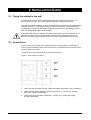
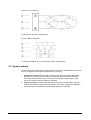
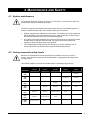
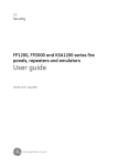
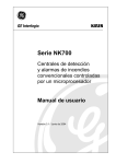
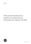
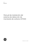
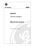
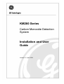
KM260 Series
Carbon Monoxide Detection
System
Installation and User
Guide
Version 2.1 / April 2004
Kilsen and Aritech are GE Interlogix brands.
http://www.geindustrial.com/ge-interlogix/emea
© 2003 GE Interlogix B.V.. All rights reserved. GE Interlogix B.V. grants the right to reprint this manual for internal use only. GE
Interlogix B.V. reserves the right to change information without notice.
CONTENTS
1
Introduction............................................................................................................................................ 4
1.1 General description ....................................................................................................................... 4
1.2 System components...................................................................................................................... 4
2
Installation Guide .................................................................................................................................. 5
2.1 Fixing the cabinet to the wall......................................................................................................... 5
2.2 Connections .................................................................................................................................. 5
2.3 System startup .............................................................................................................................. 6
3
User Guide ............................................................................................................................................. 7
3.1 Zone module keypad..................................................................................................................... 7
3.2 Zone module keys......................................................................................................................... 8
3.3 Operating states............................................................................................................................ 9
3.4 Configuration................................................................................................................................. 9
4
Maintenance and Safety ..................................................................................................................... 11
4.1 System maintenance................................................................................................................... 11
4.2 Carbon monoxide safety levels................................................................................................... 11
5
Technical Specifications .................................................................................................................... 12
KM260 Series Carbon Monoxide Detection System
3
1 INTRODUCTION
1.1 General description
The GE Interlogix carbon monoxide (CO) detection system is the ideal solution for
detection of dangerous levels of CO gas in car parks and other enclosed spaces where
levels of CO gas must be monitored and controlled effectively.
The detection system is based on the analysis of polyatomic gas molecules in the air and
uses a rapid-acting (under ten seconds) SnO2 doped semiconductor housed in the head
of the detector. CO levels are sent to and displayed in the control panel and ventilation
and alarm relays triggered automatically when user-defined CO levels are detected.
System features:
Easy to use modular design that provides flexible CO protection for 1 to 5 zones.
Detection response of less than 10 seconds (using GE Interlogix KM170 CO
detectors).
Use of up to 15 detectors per zone.
Coverage from 300m2 (single zone) up to 22,500m2 (five zones) using a single
cabinet.
Two relay outputs (ventilation, alarm) triggered by user-defined CO levels.
Advanced system testing and self-testing functions to ensure reliable detection at all
times.
The CO detection system is available in the following versions:
Model
Zones
Cabinet size
Extra zones installable
KM260/1
1
275 mm x 335 mm x 130 mm
1
KM260/3
3
470 mm x 335 mm x 130 mm
2
1.2 System components
1 x cabinet, available in two sizes:
275 mm x 335 mm x 130 mm (for 1 or 2 zone modules).
470 mm x 335 mm x 130 mm (for 3 to 5 zone modules).
1 x voltage transformer.
1 x mains source connecting header.
KM170 CO detectors (sold seperately).
4
KM260 Series Carbon Monoxide Detection System
2 INSTALLATION GUIDE
2.1 Fixing the cabinet to the wall
Fix the cabinet to the wall at an approximate height of 1.5 metres from the floor, in a
place with easy access. The zone module LED display should be at eye-level.
The cabinet must be installed in a clean, dry place free from vibrations with a temperature
between 0 and 60º C. The relative humidity must not exceed 95%. There should be no
condensation. The place of installation should be protected by the CO detection system.
Risk of mechanical damage must be avoided.
Create the cable holes you require in the metal cabinet before fixing it to the wall. Do not
perforate the panel in places other than those indicated. Avoid dropping shavings or
pieces of removed casing inside the cabinet. PG11-type cable adapters may be used.
2.2 Connections
There is a three-terminal connector shared by all the zone modules for connecting the
mains 230 VAC and earth cables. The mains fuse is incorporated into the connector (see
Figure 3: Mains connection).
In addition each zone module has a nine-terminal connector:
Figure 1: Zone module connector
1.
Three zone line terminals: positive, negative and data. See Figure 2: Line connection.
2.
Three terminals for the ventilation output relay (EXTR. 1): common (C), normally
open (NO), normally closed (NC)..
3.
Three terminals for the alarm output relay: common (C), normally open (NO),
normally closed (NC).
KM260 Series Carbon Monoxide Detection System
5
Figure 2: Line connection
1. Positive line; 2. Data; 3. Negative line.
Figure 3: Mains connection
1. Fuse (pre-installed); 2. Live AC (fused); 3. Earth; 4. Neutral AC.
2.3 System startup
Once all connections have been completed and zone detectors installed the zone module
may be switched on and a system test performed. To do this:
6
1.
Press the on-off key. When the zone module is first switched ON the LED display
indicates On until an initial CO reading is provided by the zone module detectors.
During this initial period the power on-off key LED indicator will flash green. It will
remain lit once the initial CO reading is confirmed.
2.
Press the Test key. This will verify the proper working of the LED display, the zone
module LED indicators and the acoustic buzzer. The number of detectors installed in
the zone will also be assessed. Any fault discovered will be indicated.
KM260 Series Carbon Monoxide Detection System
3 USER GUIDE
Each zone in the CO detection system is controlled and configured by an independent
zone module.
Zone CO levels are passed to the zone module from the detectors and the highest CO
level detected is displayed on the LED display as Parts Per Million (PPM) of the sampled
air.
3.1 Zone module keypad
1.
2.
3.
4.
5.
6.
7.
8.
LED display
Power on-off key / LED
Mute key / LED
Test key
* (star) key
Alarm LED
Ventilation LED
Fault LED
KM260 Series Carbon Monoxide Detection System
150 PPM LED
100 PPM LED
50 PPM LED
Level key
Automatic mode LED
14. Manual mode LED
15. Stopped LED
16. Mode key
9.
10.
11.
12.
13.
7
3.2 Zone module keys
Power on-off Key
The on-off key switches the zone module ON and OFF.
When the zone module is OFF it is indicated in the unit LED display and in the power onoff key LED indicator.
Mute key
The mute key silences the internal buzzer and disables the alarm output relay. When the
mute key is active the key LED indicator is red.
Test key
Used to verify the proper working of the LED display, the zone module LED indicators
and the acoustic buzzer.
* (star) key
The * key has two functions:
1.
Alarm level indication and selection
If the zone is quiescent pressing the * key will display the pre-defined CO alarm level
flashing in the unit LED display. This level may be changed using the Level, Mode
and Mute keys:
Mute = increments of 5
Mode = increments of 10
Level = increments of 100
2.
Fault code indication
If the zone is in fault condition, (indicated by the fault warning indicator and the
intermittent buzzer), pressing the * key displays the code of the fault detected.
The fault codes are:
500
Scanning fault.
501
Detector fault (filament breakage).
502
Low line voltage level.
503
Detector missing.
504
Excessive power consumption.
Exit alarm or fault indication by pressing the * key. Indication will exit automatically if no
key is pressed for 15 seconds.
Level key
Used to set the CO concentration level that will trigger the ventilation relay output.
8
KM260 Series Carbon Monoxide Detection System
Mode key
Used to select the different operating modes for ventilation:
Stopped.
Manual.
Automatic.
Stopped mode disables the ventilation system.
Manual mode manually activates the ventilation relay output.
Automatic mode triggers the ventilation output when one of the detectors in the zone
reaches the pre-defined alarm level. Ventilation is preceded by a short user-defined
waiting period in which the ventilation LED indicator flashes. This LED indicator is
constant during ventilation. Ventilation continues for a short period after CO levels have
decreased.
3.3 Operating states
The CO detection system operates in the following states:
Quiescent.
Alarm.
Ventilation.
Fault.
An alarm, ventilation or fault state is indicated by the red, green or yellow LED indicators
on the zone module keypad (see section 3.1 Zone module keypad).
Quiescent: This is the normal operating state where no event is indicated. The module
displays the highest CO concentration level in the zone covered by the module in the
display LED.
Alarm: There is an alarm. When the alarm level is reached, and after a set period for
verification, the module activates the red alarm LED indicator, the alarm output relay and
the acoustic signal..
Ventilation: Ventilation is active. The green ventilation LED indicator is lit.
Fault: There is a fault. Once a fault is detected the module will activate an intermittent
acoustic signal and the yellow fault LED indicator: The fault code is displayed by pressing
the * key. There is a user-defined delay before any fault is indicated by the system. Once
a fault has been fixed press the Power on-off key to reset the system.
3.4 Configuration
To enter Configuration Mode press the * key and the Test key at the same time.
There are 17 numbered options that may be configured. On entering Configuration Mode
option 1 (Ventilation level 1) is displayed.
Use the Level, Mode and Mute keys to modify numeric values.
Use the Mute key to modify on / off values.
The * key confirms the entry and displays the next option.
KM260 Series Carbon Monoxide Detection System
9
To exit Configuration Mode use the * key to cycle through all options – Configuration
Mode will exit after the final option. Configuration Mode will exit automatically if no key is
pressed for 15 seconds.
Configuration options and their default values can be seen in Table 1: Configuration
options and default values.
Table 1: Configuration options and default values
Option
Description
Default value
1
Ventilation level 1
50
2
Ventilation level 2
100
3
Ventilation level 3
150
4
Relay alarm activated with alarm
ON
5
Relay alarm activated with fault
OFF
6
Relay alarm activated with ventilation
OFF
7
Relay alarm deactivated with mute
ON
8
Missing detector detection
OFF
9
Number of alarms detected *
0
10
Number of ventilations performed *
0
11
Delay time for Mode key (in seconds)
20
12
Confirmation delay to activate ventilation
(in seconds)
60
13
Confirmation delay to deactivate ventilation
(in seconds)
120
14
Idle time to exit * mode (in seconds)
15
15
Confirmation time to alarm activation
(in seconds)
20
16
Confirmation time to fault activation
(in seconds)
120
17
Number of detectors in loop
Calculated automatically
during test procedure after
system setup.
* Use the Mute key to reset alarm and ventilation values.
10
KM260 Series Carbon Monoxide Detection System
4 MAINTENANCE AND SAFETY
4.1 System maintenance
Do not tamper with zone module circuit board or electronics. In the event of a fault only
qualified personel should attempt fault repair.
The built in system and self-testing functions ensure that your CO detection system is
always in perfect working order. For increased safety we recommend:
Regular inspection and calibration of the system. The frequency of such inspections
will be decided by environmental factors such as relative humidity, excessive dirt or
dust and concentration of any other contaminating gases.
A log book of all faults reported by the system (or the result of an inspection) should
be kept and the resolution date recorded. The log book should be referred to
regularly to ensure all faults have been repaired.
The useful lifespan of GE Interlogix CO detectors is 4 years. Detectors and / or
sensing elements must be serviced or replaced within this time frame.
4.2 Carbon monoxide safety levels
Maximum recommended CO levels and exposure guidelines vary from country to
country. Your detection system should be calibrated to comply with local safety levels
and regulations.
The following table of CO levels and health effects is provided as a guide only.
2
5
15
40
120
minutes
minutes
minutes
minutes
minutes
200
Headache
PPM
400
Headache
Dizziness
Headache
Dizziness
Unconsciousness
Headache
Dizziness
Unconsciousness
Death
Headache
Dizziness
Unconsciousness
Death
Dizziness
Unconsciousness
Death
Unconsciousness
Death
PPM
800
PPM
1600
PPM
3200
PPM
6400
PPM
12800
PPM
KM260 Series Carbon Monoxide Detection System
11
5 TECHNICAL SPECIFICATIONS
Cabinet size (1 or 2 zones).....................................................275 mm x 335 mm x 130 mm
Cabinet size (3 to 5 zones) .....................................................470 mm x 335 mm x 130 mm
Mains power supply ........................................................................... 230 VAC ±10% / 95W
Maximum consumption................................................................. 100 mA per zone module
Mains fuse................................................................................................. 500 mA 5x20 mm
Zone module input voltage .................................................................................... 9-23 VAC
Number of relays............................................................................................. 3 (C, NO, NC)
Maximum line length ....................................................................................................350 m
Maximum number of detectors per zone ...........................................................................15
Measurement range.........................................................................................0 to 300 PPM
Programmable alarm level...............................................................................0 to 295 PPM
Selectable ventilation relay levels.............................................................50, 100, 150 PPM
LED Display ............................................................................................................... 3 digits
Ventilation level indication ............................................................................... LED indicator
Ventilation modes ..................................................................... automatic, manual, stopped
Ventilation mode indication.............................................................................. LED indicator
Alarm indication ..........................................................................acoustic and LED indicator
Fault warning indication ..............................................................acoustic and LED indicator
Operating temperature............................................................................................0 to 60ºC
Storage temperature ........................................................................................... -10 to 70ºC
Maximum humidity ......................................................................................................... 95%
12
KM260 Series Carbon Monoxide Detection System
1049370