1
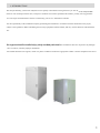
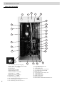
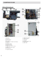
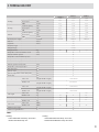
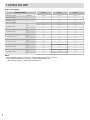
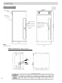
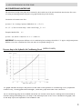
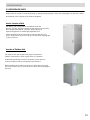
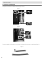
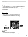
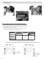
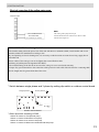
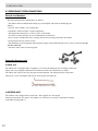
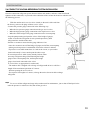
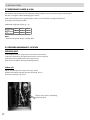
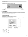
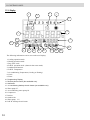
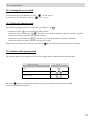
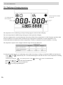
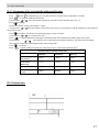
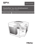
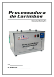
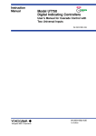
SPLIT MULTIFUNCTIONAL
GEOTHERMAL HEAT PUMP
(Heating, Cooling and Domestic Hot Water)
Built-in 2 water tanks
3GEO-15
3GEO-19
3GEO-23
INSTALLATION AND START-UP MANUAL
INDEX
1. INTRODUCTION
........................................................................................................................
1
2. DESCRIPTION OF UNIT ............................................................................................................ 2
3. TECHNICAL DATA ....................................................................................................................... 5
4. ELECTRIC DATA ..........................................................................................................................
6
5.OPERATING LIMITES
..................................................................................................................7
6. DIMENSIONS
..................................................................................................................8
7. SERVICE AREA
10
...................................................................................................................
8. AIR CONDITIONING WATER PUMP ....................................................................................11
9. INSTALLATION
.....................................................................................................................12
9.1.Safety Consideration
.................................................................................................12
9.2. Location of the units
................................................................................................13
9.3. Hydraulic Connection...............................................................................................14
9.4. Electrical Connection ................................................................................................19
9.5. Refrigerant Connetion................................................................................................22
9.6. vacuum in the refrigeration system .....................................................................23
9.7. Recharge Refrigerant (R-410A) ............................................................................24
9.8. Pressure Measurements ............................................................................................24
10. STARTING UP
.................................................................................................................................25
10.1. Checks before Startup.............................................................................................25
10.2. Checking Power Supply.........................................................................................25
10.3. Temperature Settings
............................................................................................ 25
10.4. D.H.W. (Domestic hot water) mode operation.............................................26
10.5. Air Condition Mode Operation
.......................................................................................
26
11.CONTROL PANEL ...........................................................................................................................28
11.1. Pressure Indicator ...................................................................................................... 27
11.2. Electronic Controller ............................................................................................... 27
11.3. LCD Screen .................................................................................................................
28
12. UNIT OPERATION ..................................................................................................................... 29
12.1. Startup and Shutdown of Unit .............................................................................. 29
12.2. Operation Mode Selection .....................................................................................
29
12.3. Signaling Mode Operation..................................................................................... 29
12.4. Temperature Display and Modification ........................................................... 30
12.5. Clock and Timer.........................................................................................................
31
13. ALARMS.............................................................................................................................................. 34
14. SOLAR SYSTEM CONNECTION ..................................................................................... 36
15. ELECTRIC DIAGRAM............................................................................................................. 38
16. MAINTENANCE .......................................................................................................................... 42
17. HEAT PUMP TEST RUN.............................................................................................................43
1. INTRODUCTION
The unit purchased by you has been subjected to strict quality control before leaving the factory. It also me ets the safety standards
of the CE. Do not tamper with the unit ,or subject to conditions of work not specified in this manual, you may lose any guarantee
on it. The repair and maintenance must be con ducted by your service / maintenance installer.
It is the responsibility of the installation company performing the installation in accordance with the characteristics the project,
subject to the regulations. Before installating the necessary equipment read this manual, and carry out the directions and obserations
in it.
This equipment should be installed only by a duly accredited professional.The manufacturer does not responds to any damages
and / or indirect, caused by improper installation.
You should check the receiving unit, which is in perfect condition. If otherwise appropriate to make a written complaint to the carrier.
1
2. DESCRIPTION OF UNIT
Indoor Unit (all models)
1
2
25
4
3
24
6
5
20
7
8
10
9
11
14
12
14
21
13
22
15
16
26
17
2
1. Air conditioning water pressure gauge
2. Electric heater 2kW with thermostat for DHW
3. Check Valve ¾ "
for DHW
4. LCD controller
5. Heat exchanger for DHW
6. DHW temperature sensor
7. DHW accumulation water tank
8. Check Valve ½ " for DHW
9. DHW water pump (secondary)
10. Check Valve ½ " for DHW
11. DHW water pump (primary)
12. Air Conditioning Water inlet temperature sensor
13. Air conditioning Heat exchanger
14. Air conditioning water shut off valve 1 "
23
18
19
15. Air conditioning water tank
16. 1-way electric valve
17. 3-way electric valve
18. Air-conditioning water outlet sensor
19. Air conditioning expansion tank
20. DHW safety valve
21. air conditioning control safety valve
22. 1-way electric valve
23. 3-way electrical valve
24. DHW expansion tank
25. Electric control box
26. Electric heater 3x2kWwith thermostat for A/C
2. DESCRIPTION OF THE UNIT
3GEO-15/19/23 outdoor unit
5
6
7
13
20
14
11
16
8
10
12
9
21
13
1
17
18
3
4
19
2
22
1.water inlet
2. water outlet
3. Liquid connection
4. Gas connection
5. Flow switch
6. Temperature control plate heat exchanger
7. Compressor
8. Low pressure switch
9. Gas-liquid separator
10. High pressure switch
11. High-pressure liquid accumulator
12. Bypass valve
13.Compressor crankcase heater
14. Four-way valve
15. Compressor Capacitor
3
16. High pressure switch
17. Electronic board
18.
19.
20.
21.
22.
Transformer
Contactor
Thermal expansion valve
Needle valve
Drain valve
4%#(.)#!,$!4!3(%%4
TECHNICAL DATA
Heating
Cooling
D.H.W.
3GEO-19
3GEO-15
Nominal capacity
kW
13,20
17,30
21,00
Power input
kW
3,05
3,65
4,80
COP
W/W
4,33
4,74
4,38
Nominal capacity
kW
15,10
18,80
23,20
Power input
kW
3,25
3,95
5,20
EER
W/W
4,65
4,76
4,46
Nominal capacity
kW
12,50
16,10
19,40
Power input
kW
3,80
4,75
5,65
COP
W/W
Electrical power supply
V/Ph/Hz
Gas line
Inches
Liquid line
Inches
3,29
3,39
3,43
230/1/50
400/3/50
400/3/50
3/4
3/8
Compressor type
Scroll
Refrigerant type
R-410A
Refrigerant load
Kg
Temperature control accumulator volume
Litres
50
D.H.W. maximum pressure
Litres
90
Temperature control maximum pressure
Bar
3
Temperature control expansion tank volume
Litres
6
D.H.W. maximum pressure
Bar
7
D.H.W. expansion tank volume
Litres
2
Temperature control input/output
mm
28
Tap water input
mm
15
D.H.W. output
mm
15
D.H.W./Temperature control safety valve
mm
15
Drain valve
mm
15
Net weight
Packaged weight
Noise level
3,0
3,15
Indoor unit
mm
(Height xWidth x Length)
1.360x590x590
Outdoor unit
mm
(Height xWidth x Length)
645x692x452
Indoor unit
mm
(Height xWidth x Length)
1.470x650x650
Outdoor unit
mm
(Height xWidth x Length)
700x750x500
Indoor unit
kg
Outdoor unit
kg
70
Indoor unit
kg
140
Outdoor unit
kg
75
80
Indoor unit
dB(A)
Outdoor unit
dB(A)
32
33
Dimensions
Dimensions Packaged
Product
3GEO-23
128
4,1
132
75
80
144
85
28
Maximum pipe length
m
50
Maximum height difference
m
30
34
NOTES:
Heating:
- Indoor inlet/outlet water temp. 30°C/35°C
- Outdoor inlet brine temp. 0°C
Cooling:
- Indoor inlet/outlet water temp. 23°C/18°C
- Outdoor inlet/outlet brine temp. 30°C/35°C
4
%,%#42)#!,$!4!3(%%4
Power consumption
TECHNICAL PROPERTIES
3GEO-15
3GEO-19
3GEO-23
230/1/50
400/3/50
400/3/50
Operating voltage
V/Ph/Hz
Minimum voltage
V
200
345
345
Maximum voltage
V
253
440
440
kW
3,25
3,95
5,20
A
14,1
5,70
7,51
kW
3,05
3.65
4,80
A
13,3
5,27
6,93
kW
3,80
4,75
5,65
A
16,5
6,86
8,16
kW
4,05
5,25
6,25
A
17,6
7,6
9,0
kW
4,20
5,20
6,30
A
18,3
7,5
9,1
kW
4,20
5,20
6,30
A
18,3
7,5
9,1
Power consumption
Nominal cooling *
Nominal heating **
Nominal D.H.W. ***
Maximum cooling
Maximum heating
Maximum D.H.W.
NOTES:
* Indoor inlet/outlet water temp. 23°C/18°C ; Outdoor inlet/outlet brine temp. 30°C/35°C
* * Indoor inlet/outlet water temp. 30°C/35°C ; Outdoor inlet brine temp. 0°C
* * * Water storage temp 40°C; Outdoor inlet brine temp. 0°C
5
6. DIMENSIONS
Indoor Unit (all models)
Controlador
electrónico
Manómetro
Switchboard
Output connections
Output connections
electrical, hydraulic
electrical, hydraulic
refrigerant gas and
refrigerant gas and
liquid line
liquid line
1.360/1.380
Gateway to
Indoor unit
590
NOTA:
Dimensions in mm.
590
Outdoor Unit Dimensions 3GEO-15/19/23
C
A
Liquid
connection
Gas
connection
E
D
MODEL
6
3GEO-15
3GEO-19
3GEO-23
B
A
645
645
645
B
692
692
692
MEASUREMENTS (in mm)
C
452
452
452
D
470
470
470
E
420
420
420
7. SERVICE AREA
The following is the minimum space needed to carry out the tasks of service and maintenance of the units.
1.000
Indoor Unit (all models)
Outdoor Unit (all models)
NOTE:
Dimensions in mm.
7
8. AIR CONDITIONING WATER PUMP
AIR CONDITIONING WATER PUMP
The selection of coolig water pump to be mounted by the installer out of the unit should take based on the flow rates
of cooling and heating,internal drop unit (see graph) and the drop of the facility.
Calculation of nominal water flow:
Q water (l / h) = Cooling Capacity* 0.86 (Kcal / h) / △T (º C)
As △T = (T first exit water temp - water return Temp) _T = 5 º C
Example: Model 3GEO
-15
Q water = (16,300 W * 0.86) Kcal / h / 5 ° C = 2800 l / h
IMPORTANT: The temperature difference in air conditioning heat exchanger should be 5 º C approx.A high temperature
difference can cause a malfunction of the unit and even irreparable damage to it.
Available pressure (kPa/m.c.a)
Pressure drop in the Hydraulic Air Conditioning Circuit (3GEO-15/19/23)
Water flow (m3/h - l/s)
This graph indicates the drop in the pressure of the water in the hydraulic air conditioning circuit (components
inside the unit), including plate heat exchangers, water filter, pipes and water hose connection.
The air conditioning pump to be installed outside the unit must be chosen by the installing technician based on
nominal cooling and heating flows, on drops in the internal pressure of the unit as indicated in the graph, and
on the drop in pressure expected in the installation itself.
8
9. INSTALLATION
9.1 SAFETY CONSIDERATIONS
Here are a series of recommendations to follow for proper installation of the unit.
Installation,repair and maintenance of these units must be made with caution because the presence of electrical,
electronic and circuit pressure system refrigerant.Only trained and qualified personnel should perform all
installation,adjustment and maintenance unit.
The manufacturer declines all liability for negligence and breach of safety standards described below:
- Work in total safety, free from obstacles and clean environment.
- Comply with regulations.
- Before commissioning of the unit, excellent condition confirm the same and its components.
- Wear safety goggles and gloves while working. Use quenching cloth during operations welding.
- Put in place strong units that can support the weight bearing and allow the right posterior maintaining it.
- Use the specified cables and make a proper connection at the terminals.
- Make a separate attack unit.
- Check the supply voltage corresponds to the plate.
- Perform the corresponding ground.
- Perform the work safely install hydraulic and drainage pipes as shown of this manual.
- During operation of the drive circuit part5s refrigerant. (compressor line download) can reach temperatures.
above 70 º C. Take special care when accessing the inside the unit.
- The unit can work in environments "normal" residential, commercial or light industry. The unit can not be installed in
explosive atmosphere environment. For applications Special should consult the manufacturer.
Very important!
Before starting the installation or maintenance operations of the unit disconnect switch general power. Electrical
shock can cause personal injury.
9
9. INSTALLATION
9.2 LOCATION OF UNITS
Inspect units of receipt to verify any damage or damage during transport. If the unit is damaged you must file a claim
immediately to the company who made the shipment.
Interior Location of Unit
The indoor unit is designed for installation inside the
housing. For this, the inner cabinet has the same action at its base
that a common household. It also has the possibility of
adjust its height due to small height-adjustable feet.
When installed inside the unit must be left open the door area
access, being necessary to leave the spaces described in paragraph
7 (Service Areas).
Location of Outdoor Unit
The outdoor unit must be placed in proper orientation to
climatic characteristics of the region where it is installed.
It should be positioned so that air circulation is free and well
avoid recirculation effects detrimental to performance.
When installing the outdoor unit must be left free the front of the
unit, which is necessary to leave the spaces described in paragraph 7
(Service).
10
9. INSTALLATION
9.3 HYDRAULIC CONNECTIONS
All hydraulic connections are labeled as shown in Figures 1 and 2:
Figure 1
DHW output.
Main water inlet
Figure 2
Climate water inlet
Climate water outlet
The unit is supplied with a flexible sleeve to facilitate circuit hydraulic connections air conditioning (Figure 3).
Figure 3
11
9. INSTALLATION
It is necessary to conduct the common outlet safety valves of the two tanks to drain (figure 4).
Figure 4
Drain output
Hydraulic Circuit Climate
- Water pump
The operation of closed circuit cooling, means that water must be transported heating or cooling energy from the unit Triaqua to
secondary and this installation is performed by forced circulation water pump.
.
This water pump must be placed by the installer and should be calculated for water flow required and to overcome the pressure drop
(installation + machine) .See section 8
For electrical connection, see Section 9.4 (Electrical Connections).
IMPORTANT: A small pump may cause a malfunction or even a fault irreparable.
- Flow Switch
To avoid potential problems in the unit for lack of water in the cooling circuit, the unit incorporates a flow switch.
IMPORTANT: The water shortage could cause irreparable damage to the unit.
- Differential pressure valve
To ensure that water always returns to the unit in the cooling circuit,install a differential pressure valve. The differential pressure
valve guarantees the minimum flow required for proper functioning of the heat pump when there is closure of the thermostatic
valve and limits differential pressure of the installation.
IMPORTANT: If water does not return the unit, it could cause an irreparable damage to that unit.
12
9. INSTALLATION
Filling and pressure testing for DHW circuit
To fill water tank DHW, proceed as follows:
Filter built inside of pressure reducer
3
2
1
Figure 5.1
1. Mains water inlet
4
2. Pressure reducer
3. Manometer
4. Stopcock pressure reducer
5. Conditioning circuit filling valve
5
-
- Connect the power supply, NOT SWITCHING ON THE UNIT.
- Perform opening the water inlet tap the network of the unit (see Fig.5.1)
- Open tank trap DHW (Fig.5.2) and the bleeder on the top of the water pipe connecting the heat exchanger climate with
DHW (Fig. 5.3). Close both traps when you stop air and water comes out.
- Open a point of hot water consumption to flush the system.
- The indoor unit includes a pressure regulating valve (factory calibration 2.5 Bar). If necessary, adjust the inlet
pressure to the unit (n ormal 2.5 to 3 Bar).
Figure 5.2
Figure 5.3
- Check the correct rotation DHW pumps through access to the same axis through the screw maintenance.
13
9. INSTALLATION
Filling and Pressure Testing Air Conditioning Hydraulic Circuit
-To fill water cooling tank, proceed as follows:
- Ensure that the secondary installation, underfloor heating, fan-coil, etc, has previously been filled and purged.
- With the tap water inlet of the unit open network (1) Fig.5.1, open the manual filling key conditioning circuit
(Fig.6.1) and taps (and out )air conditioning circuit unit.(Fig.6.2).
- 10 ° C AS SET SETPOINT HEATING AND DHW. Put the unit in HEATING up mode.
Input
Cut off
valve
Figure 6.2
Output
Figure 6.1
Cut off
valve
Figure 6.3
- Open the manual trap located at the top of the cooling tank and keep it open until all air is removed from the
circuit (Fig.6.3).
- Secondary installation should incorporate a trap in the top. Open the trap if necessary.
- Having gained the venting unit, shut off the circuit manual filling air conditioning (Fig.6.1), the keys must be cut
(and out) of the cooling circuit open.
- Check the cooling circuit pressure on the gauge installed in the control panel indoor unit, must be between 1 and
2.5 bar (normal 1.5 bar) for proper operation.
- Ensure that all secondary facility is found with water pressure and completely purged of air. The existence of air
in the cooling circuit can cause irreparable damage unit. It is becoming essential to make a proper venting cooling
circuit of the installation. For this reason, traps will be installed in the highest part of the circuit housing proceed to
remove all air from the facility in an appropriate manner..
14
9. INSTALLATION
- It is recommended to connect the cooling pump directly to the network, ie, pump-only water-cooling circult for a
time,to eliminate the existence of such air circuit.
Attention!
Do not connect the unit for operation of the pump. When connecting the unit and not the water pump
independently, it could cause irreparable damage in the unit.
- The unit has air conditioning in the circuit (return) a mesh filter (Fig-7), whose mission is retaining dust or dirt
which might remain in the cooling circuit of the house.
Figure 7
Attention!
The dirt from the installation may cause irreparable damage to the unit.
- Once the connections and filling, and prior to starting the unit, it is recommended operating the air conditioning
circuit pump for a while, to retain the mesh filter particles and impurities that could be installed. To this should be
wired air conditioning pump directly to the network.
- Once that is done, and the pump stopped, it should close the stopcocks input and output conditioning circuit
(Fig.6.2), drain water tank cooling through the same drain and clean the filter screen. Then fill again circuit.
- To ensure that no dirt on the circuit, should make this operation as often as necessary.
- Having established that the cooling circuit is clean, insert glycol, if necessary, approximately 20%.
- Should perform periodic reviews, including cleaning the filter screen, to ensure that there is no dirt inside the
circuit.
15
9. INSTALLATION
9.4 ELECTRICAL CONNECTIONS
Before any electrical installation work to ensure that the main switch is disconnected.
General Recommendations
- The installer must protect the power line drive disconnecting devices automatic magneto-thermal switch and
circuit breaker suitable
- for installation in accordance with the legislation.
- The power to the unit must be within a range of voltage (see table consumption electric page 8).
- It should pay special attention to the connection of ground wire. The ground wire must be of a length slightly
larger than the cable phases.
.
Preliminary operations
In the outdoor unit:
- Remove the access panel to the control panel located on the front side of the unit.
- Check that the network characteristics match the data on the nameplate of the unit.
- Perform power and interconnection between the interior and exterior units through the 2 presses on the side of
the unit.
.
Figure 8
Electric power
supply
Signal wires
interconnection
- Ensure that power cords have the correct section for the total consumption
unit. See table below.
In indoor unit:
- Open the front panel by turning the key to closing the unit.
- Ar unscrewing the structure of the unit control box, moving outward through
support guides, so we have access to the terminals of the unit (Figure 9).
16
9. INSTALLATION
Figure 9
Figure 11
Figure 10
Power supply (connection and interconnection between units)
Before commissioning of the unit must perform the following connections:
- Mains supply (outdoor unit), Figure 8.
- Interconnection between the outer and inner drive, figures 8, 10 and 11.
- Connect the air conditioning water pump, Figure 10.
MODEL
3GEO-11
-
Outdoor Power
SUPPLY
3 x 4 mm
Indoor power
SUPPLY
3 x 4 mm
COMMINICATION
SIGNAL (no polarity)
2 x 0,5 mm
3GEO-19
3GEO-23
5 x 6 mm
2 x 0,5 mm
3 x 4 mm
(no polarity)
*The power to the indoor unit can proceed directly network or coming from the outdoor unit.
The seperate connection can make the whole system electric current at least 10A lower
MODEL 3GEO -15
INDOOR UNIT
MODEL
OUTDOOR UNIT
INDOOR UNIT
2 communication cables no polarity
3 x 4 mm cables
of
3GEO -19/23
OUTDOOR UNIT
2 communication cables no polarity
SUPPLY
230/1/50
SUPPLY
ELÉCTRIC
3 x 4 mm cables de
SUPPLY
380-425/3/50
SUPPLY
ELÉCTRIC
17
9. INSTALLATION
Electrical connection of the cooling water pump
INDOOR UNIT
NOTE:
The cooling water pump must be put
outside and the electrical connection as shown in this
scheme and in Figure 10.
AIR CONDITIONING
WATER PUMP
(To be installed by the installer)
VERY IMPORTANT!: Protection against indirect contact
The installer must protect the power line of the unit with devices automatic switch ,circuit breaker and circuit
breaker,suitable for installation according to law.
By incorporating an electric heating unit, it is necessary to take them into account when sizing supply line of
the indoor unit.
Power cables of the unit type can not be lighter than coated flexible cable
Ordinary polychloroprene (designation H05 RN-F).
The commissioning of the unit in an incorrect line voltage is not covered under warranty
Triaqua. Pay special attention to the connection of the protective earth cable. Must be the first connecting cable
and its length must be greater than that of the wires.
AN5
AN3
AN4
TRA N
ON
COMM1
ON
1 2 3
SW4
LED3
LED2
FAN2
P1
LED1
TRA N S
FAN1
P2
P9
AN2
1 2 3
Three phase:
1 2 3
Single phase:
ON
* Switch between single phase and 3 phase by setting dip switch on outdoor control board
LED4 LED5
OUT3
OUT4
OUT5
L1
L2
L3
N
OUT1
Outdoor Control Board
* Other dip switch meaning of SW4
SW4-2 off means for Triaqua heat pump
SW4-2 on means for Monobloc heat pump
SW4-3 off means for air source heat pump
SW4-3 on means for Water source/Geothermal heat pump
18
9. INSTALLATION
9.5 REFRIGERANT SYSTEM CONNECTIONS
General considerations
The interconnection lines refrigerant is as follows:
- The indoor unit has identified the taking of gas and liquid, with stickers identifying, the
follows:
Gas line: Gas (coolant) / Gas (refrigerant)
Liquid line: liquid (coolant) / Liquid (refrigerant)
- All refrigerant connections, as well as water, are threaded.
- You have to isolate the lines to avoid condensation and heat loss.
- Once you have installed the lines, to empty into the circuit refrigerant indoor unit until a
-1 Kg/cm2 pressure for at least 2 hours.
- The discharge circuit refrigerant and refrigerant charge can be made through service valves located on the right
side ofthe outdoor unit.
- Check for leaks in the circuit refrigerant.
Connection between units
In indoor unit:
The indoor unit is equipped with a coupling to l evar lines threading the area of output connections
indoor unit (see paragraph 6.Dimensiones scheme) and since the connections are made .
The indoor unit comes with a dry nitrogen load incorporated. The refrigerant lines of the units
interior are a series of adapters and nuts to ensure proper seal until use.
Gas valve and liquid valve coupling
In OUTDOOR UNIT:
The outdoor unit is shipped with a load of R - 410A applies to a line length
maximum equivalent of 5 meters. For lengths over 5 meters is necessary to add load according
to the table in paragraph 9.7.
19
9. INSTALLATION
9.6 CONDUCT OF VACUUM REFRIGERANT SYSTEM INSTALLATION
Once the connection refrigerant system between indoor and outdoor, and once it has been found
tightness of this connection, we proceed to the realization of the vacuum in the unit to which it will
the following process:
- With the outdoor unit’s service valves closed (as the unit is delivered from
the factory), remove the plugs of these service valves.
- Connect the pressure gauge connection in the following way:
• Make the low pressure gauge connection to the gas service valve.
• Make the high pressure gauge connection to the liquid service valve.
• Make the centre bridge of the gauge connection to the vaccum pump.
- keep the pump running and open the valves of the bridge of gauges,
so that we ensure the refrigerant circuit system depression by both
refrigerant lines and the indoor unit.
- Perform a vacuum to ensure that the gauge indicates 1 bar.
- Once the vacuum to turn off the bridge of gauges and off the vacuum pump,
making sure that pressure is maintained vacuum for at least 15 minutes.
- If pressure is not stable means there is a leak in the circuit, so you need to
locate and remedy it. Once cured repeat the above steps.
- If vacuum pressure is stable (it may already be done when
necessary refrigerant charge) disconnecting the bridge
gauge of the vacuum pump first, and keep the bridge
gauge closed ends connected to the valves
or service lines, as appropriate for each model.
- The outdoor unit is shipped with a charge of refrigerant R-410A is valid for a
length of line maximum equivalent of 5 meters.
- Perform opening the service valves.
- For superior line lengths to 5 meters, recharge the unit as shown in table recharge
refrigerant.
Manometer pressure
Low
High
Vaccum Pump
NOTE:
- To recover all the refrigerant charge in the outdoor unit for maintenance, just to shut off the liquid valve.
After the pressure is reduced to 0 Pa, shut off the gas valve
20
9. INSTALLATION
9.7 REFRIGERANT CHARGE (R-410A)
The outdoor unit incorporates the refrigerant charge (R410A) necessary for the proper functioning of
the unit to a length of interconnecting pipe 5 meters.
If the interconnection line is greater than 5 meters, we should make a refrigerant addiction
according to the following table:
Additional refrigerant charge (g / m)
DIÁMETER
LÍQUID
GAS
3/8”
5/8”
3/4”
60
-
-
-
8
10
NOTE:
- Enter
the refrigerant charge in liquid phase.
9.8 PRESSURE MEASUREMENT. LOCATION
OUTDOOR UNIT
In the outdoor unit has two pressure connections (suction and
compressor discharge), through which pressure can be measured
evaporation and condensation of the system in any
three functions (DHW, Heating and Refrigeration).
Indoor unit
Indoor unit incorporates two pressure taps, which
DHW mode heating and high pressure measured, and so
measured cooling low pressure.
High or low pressure, depending
Operating mode
21
10. STARTING UP
10.1 CHECKS TO BE PERFORMED BEFORE STARTING UP
- Confirm that the power is in accordance with the nameplate of the unit and been conducted according to current
regulations.
- Ensure that all electrical connections are well made and according to wiring diagram.
- Check the air conditioning filter is clean water.
- Check that the deposits of inertia of climate and the accumulation of DHWare filled with water and has made the
corresponding vent through the manual traps.
- Check the setting pressure filling group. This pressure must always be less than 2.5 Bar
- Check that all door panels are properly mounted with screws for you.
- Check that all valves of the hydraulic system of air conditioning are open.
- The operation and use of electronic control is explained in Chapter 12. Electronic Controller.
10.2 POWER CHECK
After performing the electrical installation manual for installation and connection electrical, check the following:
- Check the firmness of the attachment of power cables and switching in both the outdoor unit and the inside.
- Activate the differential electrical circuit breaker of the unit.
- Check that the tension in the outdoor unit is located between the indicated value range in the table in paragraph 4
(electrical data). If you were outside these values should not be starting the unit.
10.3 TEMPERATURES SELECTION
- The unit is operated through electronic controller multiprocessor.
- To start the unit press the Start / Stop for 1 second.
- You can select the following modes:
• Hot water. The unit produces only D HW
• Water heating and cooling. The priority is to satisfy the demand for DHWwhen such demand is s atisfied, we continued
with the production of cold water for cooling.
• Hot water and heating. The priorit y is to satisfy the dema nd for D HWw hen such demand is satisfied, we continued with
the production of hot water for heating.
- Changing temperatures.
• The unit is shipped with a set point temperature selected by default.
• Modify and adapt these temperatures to the installation of side we have: soil heating, fan coil, etc..
• In extreme weather conditions may be appropriate to amend these
10.4 OPERATION IN MODE D.H.W.(Domestic hot water)
- Enable the operation of the unit in DHW, as indicated in paragraph 12 of this manual.
-Once enabled mode, the unit will start to get selected setpoint temperature. Having gained such a set temperature ,the
unit will stop.
- Check the pump rotation DHW.
-In the first implementation of the unit, you should consume DHW to the temperature of selected accumulation.
10.5 OPERATION MODE AIR CONDITIONING
-Enable the operation of the unit heating or cooling mode,as shown in paragraph 12 of this manual.
the unit will start and send hot or cold water (depending on heating or cooling)
- After you enable the selected mode, and whenever the unit is not working hal and DHW mode, the unit will start and
send hot or cold water (depending on heating or cooling of the secondary cooling circuit to achieve the set temperature
selected.
-Once you have obtained this temperature, the unit will stop, but the cooling water pump continue in operation.
- In operation for heating and cooling, check the water temperature drop (Temp drive - T ª return). This jump should be
about 5 ° C.
22
11. CONTROL PANEL
The control panel is located on the top of the unit for all model:
LCD Controller
Pressure Indicator
11.1. Pressure indicator
The pressure indicator shows the water pressure of the air conditioning circuit, which must always be between
50 and 250 kPa (0.5 and 2.5 bar).
If the pressure is outside of these limits, call the support service..
11.2. Electronic control system
The unit is managed using a multiprocessor electronic control system.
The user interface is made up of a Display, which shows the status of the unit, 6 keys for selecting the operating
mode, the desired temperature, etc. and a status LED.
1
1.
2.
3.
4.
5.
6.
On/Off
Operating mode selector
Down Cursor
Up Cursor
Enter. Confirmation
Clear Button C
2
3
4
5
6
M
23
11. CONTROL PANEL
11.3. Display
4
1
5
2
3
6
7
9
8
10
11
20
12
13
14
15
16
The following information can be seen on the user Display:
1. Cooling operation mode.
2. Heating operation mode.
3. Day of the week.
4. D.H.W. operation mode. (domestic hot water mode)
5. Antibacterial function.
6. D.H.W. Temperature
7. Air conditioning Temperature (Cooling or Heating).
8. Clock.
9. Timer.
10. Programming Display.
11. Remote phone control (Not available now).
12. Antifreeze.
13. Air conditioning backup electric heater (not available now).
14. Water pump C7.
15. Air conditioning water pump C8.
16. Compressor.
17. Defrost.
18. Outdoor fan.
19. Water pump C5.
20. D.H.W. backup electric heater
24
17
18
19
12. UNIT OPERATION
12.1. Switching the unit on and off
To start the unit, press and hold the on/off key
To stop the unit, press and hold the on/off key
for one second.
for one second.
12.2. Selecting the operating mode
The following operating modes can be selected by pressing the key M :
- Domestic hot water
. The unit will only produce D.H.W.
- Domestic hot water and cooling.
The priority is to satisfy the demand for D.H.W., and when satisfied,
the unit will continue to produce cold water for cooling.
- Domestic hot water and heating
The priority is to satisfy the demand for D.H.W., and when
satisfied, the unit will continue to produce hot water for cooling.
When the unit is switched on by pressing the on/off key
the last operating mode used in the unit is applied.
.
12.3. Indication of the operating mode
The icons that appear on the display for the selected operating mode are indicated in the following table
OPERATION MODE
ICON
D.H.W.
D.H.W. + Cooling
D.H.W. + Heating
+
+
The symbol
appears on the display automatically when you connect the electric heater of DHW
to prevent the formation of bacteria.
25
12. UNIT OPERATION
12.4. Displaying and changing temperatures
Water temperature for DHW
storage tank
Air conditioning water
tank temperature
The temperature of air conditioning (cooling or heating) appears on the left side of Display.
The water temperature for DHW storage tank appears on the right side of Display.
The unit is shipped with a set point temperature selected by default. These temperatures are ideal for proper operation under
normal conditions. In extreme weather conditions may be appropriate to amend these set point temperatures. It is
recommended that the modification of these temperatures is made in consultation with your installation / servicing.
The temperature setpoint can be changed within the range listed in the table below:
MINIMUM
D.H.W. (Accumulator tank)
Heating (Temp Return)
Cooling (temperature Return)
Anti-bacteria
TEMPERATURE
DEFAULT
MAXIMUM
10ºC
50 ºC
45 ºC
10ºC
10ºC
60ºC
50ºC
25ºC
70ºC
40ºC
12ºC
65ºC
To change the temperature for air conditioning return (either for heating or cooling), accumulation DHW and Anti-bacteria:
- Press M and C simultaneously for 3 seconds until the digits on the left side of the screen (temperature of heating
/ cooling) blink.
- Selected by pressing the
M
key operating mode. Cooling
or heating
, D.H.W. and Anti-bacteria.
- With the keys
and
select the desired temperature.
- Press
to confirm the selected temperature.
- Press C to exit the programming box.
26
12. UNIT OPERATION
12.4.1 Programming of the anti-legionella (antibacterial function)
- Press
M and C simultaneously for 3 seconds. Enter the selection mode temperature controller.
- Press M to reach the antibacterial function.
- Using buttons
or
select the desired temperature resistance for this function (60 to 70 º C).
- Press
to confirm.
- Flashes the number of days (the default is 7 days).
- Using buttons
or select the number of days between a process of Anti-bacteria and the following (values between
7 days and 99 days).
- Press
to confirm. Word ON is lit and flashing digits on the clock time.
- Using buttons
or
to select the start time.
- Press
to confirm. Disappears and appears illuminated ON/ OFF and flash the minute digits on the clock
- Using buttons
or
select minute cycle (values between 10 and 99 minutes). This time start discounting
once and has reached the selected temperature in the storage tank.
- Press
to confirm.
- Press
C to finish. When pressed by the end of the process, would set the defaults above.
ANTIBACTERIAL HEATER FUNCTION
MINIMUM
D.H.W. storage max
MAXIMUM
DEFAULT
60 ºC
70 ºC
65 ºC
2 ºC
15 ºC
2 ºC
10 minutes
99 minutes
10 minutes
7 days
99 days
7 days
temperature
Temperature
differential
Cycle duration time
Time between
cycles
12.5. Clock and timer
27
12. UNIT OPERATION
To adjust the clock, must follow this process:
- Press the M button for 6 seconds. The digit day of the week begins to blink. For example "4" (Thursday)..
- Press the teclass or
to select the day (between 1 - Sun.).
- Press
to confirm. Then begin to flash the hour digits.
- Press the
or
button to select the hour (between 0 and 23).
- Press
to confirm. Then start the digits for the minutes.
- Press the
or
button to select the minute (0 - 59).
- Press
to confirm.
- Press
C to exit the programming process at any stage when.
- Pressing C
before it is finished, the clock will remain with the time that had initially.
The controller has a timer to set the STARING and stop unit .You can program three starting points (1,3,5) and three stop
points (2,4,6) for each day of the week. You can make a separate schedule for each day of the week. There are two types of
scheduling "S" and "C". In the "S", programming made is valid only for the current week. In type "C", programming is
repeated every week. See the following figure
- Press
M and
keys simultaneously for 3 seconds to enter mode programming schedule. Shows "S" flashing
(see figure above). Pressing
changing the type of programming "S" to "C" or reverse.
- Press
to confirm the type of programming desired.
- After selecting the desired program type, the following screen:
28
12. UNIT OPERATION
- To set the first point of connection(starting), press the
M
key, the hour digits flash. See figure below
- Set the time of the connection point with the keys
. Each time you press a button increases or decreases
the time 10 minutes.
- Press
to confirm.
- To confirm the first connection point (point 1), the screen automatically appears next:
- First point appears "off" (point 2) and the hour digits flash.
- Adjust the time with the keys
. Once it's set, press the button
to confirm.
- To confirm the first point off (section 2), the screen automatically appears with the second
connection point "ON" (point 3) and the hour digits flash.
- To set the second and third connection point (points 3 and 5) and off (points 4 and 6), proceed as in the programming of the
first point (points 1 and 2)..
- After confirming the point of programming a day, the screen automatically appear the next day flashing
- Press
to confirm.
- To set the points of connection and disconnection of the day, proceed as for the previous day. See the following figure..
- Should not be necessary to program a particular day, press (C) to jump to the next day's schedule.
-To cancel all settings, press M and simultaneously for 3 seconds to go in the schedules and then press
C simultaneously for 3 seconds. The programming schedule has been canceled.
and
29
13. ALARMS
In the event of any malfunction of the unit, the electronic controller will generate an error codes that are reflected in the
table below, This code will replace the heating / cooling temperature part of the display on
the left and the LED of the display will fl ash red.
* The error code is displayed: the letter in the digit of the temperature of air conditioning and the numbers in the digits of the DHW temperature
* Error codes won’t directly display . We must press once
Error
code
E9
E1
P3
P1
P7
PD
Sensor of water
outlet from the heat
exchanger of the air
conditioning circuit
error
Sensor of water
entering the heat
exchanger of the air
conditioning circuit
error
Outdoor unit coil
temperature sensor
error
Outdoor air
temperature sensor
error
Not enough water
flow, volume in the
air conditioning
circuit.
Sensor is broken or the
connection is loose
Change or reconnect the
sensor
LED1 blinks
on outdoor
control board
8 flashes and
5 seconds off
Sensor is broken or the
connection is loose.
Change or reconnect the
sensor
7 flashes and
5 seconds off
Sensor is broken or the
connection is loose.
Change or reconnect the
sensor
6 flashes and
5 seconds off
The compressor does not work
in D.H.W. The unit will
continue to produce D.H.W.
with the electric heater.
Contact your support service
Sensor is broken or the
connection is loose.
Change or reconnect the
sensor
14 flashes and
5 seconds off
The compressor will stop for
20 minutes. It will then
continue operating and will
replace, sensor A4 by sensor
A3.
Contact your support, service
about the problem.
The unit will stop air
conditioning mode if this
anomaly occurs 3 successive
times.
When the water flow is
resumed, the error should be
cleared. If this does not occur,
contact your support service.
Sensor is broken or the
connection is loose.
Change or reconnect the
sensor
5 flashes and
5 seconds off
Water flow switch connection
loose or air conditioning water
flow volume is too small.
1. If with water flow switch on
the unit, please check if the
connection is loose or the
water flow switch is broken or
the water pump is too small.
2. If without water flow switch
on the unit, please check if the
short connection wire is loose.
Check the communication
wires and control board.
Reconnect the wires or change
wires and control board
3 flashes and
5 seconds off
Check the electric connection
and reconnection the power
cable.
Check the electric connection
and reconnection the power
cable
1 flashes and
5 seconds off
Error display
The compressor does not work
in D.H.W. The heat pump will
continue to produce D.H.W.
with the heater element.
Contact your support service
The unit will continue to
operate. The system
uses sensor d5 instead of
d3.Contact your
support service about the
problem.
The unit will continue to
operate. The system uses
sensor d3 instead of d5.
Contact your support service
Error Reason
Or water filter is blocked by dirt
-need to clean the filter as per
page 18, figure 7.
Communication
error between the
indoor LCD control
panel and the
control board
The unit will stop operating.
Contact your support service
about the problem.
Communication wire is loose
or control board is error.
PA
Outdoor Electric
connection missing
phase protection
The unit will stop operating.
Contact your support service
Power cable connection not
Correct
PA
Outdoor Electric
connection wrong
phase.
The unit will stop operating.
Contact your support service
about the problem.
Power cable connection not
correct
E4
Pressure switch
jump in high
pressure
The compressor will stop. The
unit will operate again when
normal conditions are
re-established. If this does not
start, contact your support
service
1. Vacuum is not good enough
for refrigerant circuit.
2. There is air get inside of air
conditioning water circuit.
3. There is dirt in the air
conditioning water circuit.
4. Water flow volume is too
small, water pump is too small.
5. High pressure switch is
loose or broken
Communication
error between the
indoor and outdoor
control board
The unit will continue to
produce D.H.W. with the
heater element and the water
pump. Contact your support
service.
P9
Pressure switch
jump in low
pressure
The compressor will stop. The
unit will operate again when
normal conditions are
re-established. If this does not
start, contact your support
service
PB
Solar thermal
sensor error
Valve control for solar system
will stop
EN
E5
30
Error code
meaning
Temp sensor of the
of D.H.W water
error
to see the error code.
.
Error Solution
1. Check the refrigerant
pressure.
2. Clean and purge the air from
the water circuit.
3. Clean the air conditioning
water inlet filter(Item 26 in
explosion drawing) and other
filter in the water circuit.
4. Change a bigger water
pump
5. Reconnect high pressure
switch or change the switch.
Communication wire is loose
Check the communication
or Control board is error.
wires and control board.
Reconnect the wires or
change wires and control
board
1.Power
off for minutes and power
1.Heat expansion valve need to
on again then turn on the unit.
be preheated
May repeat this 2 or 3 times to
preheat the expansion valve.
2.Low pressure switch is loose
2.Reconnect the low pressure
or broken
switch or change it
3.Refrigerant leak
3.Check the whole system to see
if the refrigerant is leaked.
Sensor is broken or the
Change or reconnect the
connection is loose
sensor
25 flashes and
5 seconds off
1 flashes and
5 seconds off
9 flashes and
5 seconds off
2 flashes and
5 seconds off
12 flashes and
5 seconds off
4 flashes and
5 seconds off
13. ALARMS
PB
E5
P2
E2
E3
PF
Antifreeze
protection(d3 or d4
≤ 1 º C)
Error in the
EEPROM memory
of inner control
board
Discharge air
temperature sensor
error
Suction
temperature sensor
error
Compressor High
temperature
Protection (115 ° C
air discharge)
Water source heat
exchange not efficient
Compressor stop
4 way valve or compressor
contactor or compressor error
Unit continue working but
without historical record
EEPROM chip loose or error
Unit stop
4 flashes and
5 seconds off
Check the 4 way valve,
compressor contactor or
compressor.
Check EEPROM on the indoor
control board
2 flashes and
5 seconds off
Sensor is broken or the
connection is loose
Change or reconnect the
sensor
16 flashes and
5 seconds off
Unit stop
Sensor is broken or the
connection is loose
Change or reconnect the
sensor
15 flashes and
5 seconds off
Compressor stop to protect the
unit, when the temp is lower,
the unit will start again. If this
error occur twice in 30
minutes, the unit will be locked
1. Refrigerant volume is low
2. Thermal expansion valve
error
3. Water flow volume is too low
1. Check the refrigerant
pressure and check if there is
leakage.
2. Check the thermal
expansion valve
3. Check the water flow
volume and check if the water
pump is small or has dust or
other problem.
11 flashes and
5 seconds off
1, not enough water flow volume.
When unit enter antifreeze 2
2.Water source heat not enough.
times in 30 minutes, show PF.
The electric heater will start
until the water is heated to 65°C
1.Check if water flow is enough
13 flashes and
5 seconds off
2.Add water pump if necessary.
3.Adjust parameter(5) Outdoor
antifreeze entering temp lower.
EF
Geo inlet water temp
sensor error
Unit stop
Sensor is broken or the
connection is loose
Change or reconnect the
sensor
EA
Geo outlet water temp
sensor error
Unit stop
Sensor is broken or the
connection is loose
Change or reconnect the
sensor
P8
Outdoor unit water
flow error
Unit stop
Water pump not big enough
Water flow switch broken
Add water pump or
replace water flow switch
21 flashes and
5 seconds off
20 flashes and
5 seconds off
18 flashes and
5 seconds off
31
14. SOLAR SYSTEM CONNECTION
Application 1 (Standard)
Connected with dual coils solar system. Solar preheating can be used for D.H.W and room heating in the same time.
Automatic solar assistant Fuzzy Logic control program built inside to save cost the
mostly.
- Our heat pump inner system can compare the solar tank temp and room heating returned water temp. the returned
water will go through solar tank if it can get extra heat from solar heating. If in cloudy day, the returned water may
not go through solar tank to avoid heat loss.
- For summer cooling circuit, inner program will always shorten the 'cooling' circuit automatically as it no need heat.
- Domestic hot water will always go through solar tank to be preheated.
So the heat pump can have a good rest in sunny day to save cost and work more in
cloudy day. Especially excellent for floor heating together with hot water application.
A/C coil
Solar coil
Single way valve
Note:
To make sure the above application working well, note the following procedure
1. Check the indoor wiring diagram in page34 for G2 port and solar water tank sensor location.
2. Solar automatic control 3 way valve(220V) need to be connected to G2 port of indoor PCB
3. Solar tank sensor from indoor PCB need to be put in the middle of the solar water tank and should be located
above the solar coil as shown above diagram.
4. Solar system need to be connected with lower coil of water tank ; air conditioning water system need to be
connected with upper coil of water tank.
32
14. SOLAR SYSTEM CONNECTION
Application 2 (optional- need special requirement for Triaqua inner DHW coil when placing order)
Solar panel or vaccum pipe is directly connected with Triaqua heat pump inner D.H.W water tank coils. The inner
recycle fluid can be brine to avoid freeze in winter. It can save one solar water tank cost.
Application 3
Connected with normal mono type solar system with water tank together with solar vaccum pipes. Applicable for
mild weather area.
33
15. ELECTRIC DIAGRAM
INDOOR UNIT (ALL MODEL)
G2:
G2:For solar Fuzzy logic auto 3 way valve
34
G3:For seasonal auto switch 3 way valve
16. MAINTENANCE
Before any maintenance or cleaning of the unit make sure the switch is off and no power to it
Routine maintenance
This section is intended for end users and is very important to maintain regular operation of the unit over time. A few operations,
carried out regularly can prevent serious intervention by the staff.
Necessary operations do not require particular expertise and are summarized in simple controls of some components of the unit.
• With a brush to remove all foreign objects such as paper, leaves, etc, who are on the surface of the outdoor coil..
- Control water flow defrost: During winter operation, occurs from time to time the defrosting of the outdoor coil. You need to
check that the drain is not blocked. If drainage is not correct, with cold temperatures, it could form a layer of ice on the base, which
would compromise the functioning of the whole system.
Periodic Maintenance
We recommend a regular maintenance by qualified personnel
Here are some checks to be performed:
DHW circuit
• Check direction of rotation of the DHW pump, and the possible presence of air on the pump.
• Check that the pressure of condensation and evaporation in this mode are accurate at all times, depending on the
temperature of DHW and outdoor air temperature.
• Check the power consumption (Amps) of the unit operating conditions at that time.
• Check that the unit in this mode to achieve the temperature selection.
• Check that when the temperature drops to DHW temperature selection, the unit starts to operate in this mode.
• Check and clean tap water inlet water filter as shown Figure 5.1
Air Conditioning circuit
• Check direction of rotation of the pump air conditioning, as well as the possible existence of air in the system.
• Check that the pressure of condensation and evaporation in this mode are accurate at all times, depending on the
temperature of cooling water flow and outside air temperature.
• Check the temperature drop in cooling water, is within the recommended range. If not, check: water pump, air in the
water circuit, dirt in the water system, etc) .
• Check the power consumption (Amps) of the unit operating conditions at that time.
• Check that the unit in this mode to achieve the temperature selection.
• Check that when the temperature drops to air conditioning temperature selection, the unit starts to operate in this
mode.
• Check and clean air conditioning water filter as shown Figure 7.
35
17. HEAT PUMP TEST RUN
Check
List
Before
Turn
On
Triaqua
Heat
Pump
Better to print this page out and make sure that you can tick all of the following items to avoid any problem
After finish the installation tasks, please check the items listed below before turn on Triaqua heat pump
T hings you should have done:
1. Power cable
Check if the power cable is connected correctly, and check if the screws have been screwed
down and tight. Please use specified cables.
2. Communication wire
Check if the communication wire is connected correctly, and check if the screws have been screwed
down and tight.Please adopt specified communication wire.
3. Water circuit
-a. Check if the water pipe s are correctly connected, and the pipe dimensions are correct.
-b. Check if all the shut off valve and manual valve is opened, check if all the joint is fastened.
-c. Check if air exhaust valves on the water terminals must be open for the 1st water recycle running
to exhaust air in the terminals.This valve can be closed when this valve drain continous water.
-d. Check if air exhaust valves for the whole water circuit is openned. An automatic purging device
has to be installed at the highest point of the water circuit.
-e. Open the maintenance screw in the middle of the water pumps(for both DHW and air conditioning
circuit) and manually rotate the water pump axis. This action should also be done when electric
power disconnected for more than 24 hours to avoid block.
4. Be sure the two water tanks are full of water. If the water tanks are empty, the electric heaters
inside is dangerous to be broken.
5. Insulation test of power supply circuit
Please inspect it by a ohmmeter of 500V
Apply the voltage of DC 500V between the power supply terminal block and the ground wire, test
the insulation resistance.The insulation resistance must be more than 2 ohms.
Triaqua
Heat
Pump
Test Run
Y es
Y es
Y es
Y es
Y es
Y es
Y es
Y es
Y es
Procedure
Switch on the power supply
1.The power indicator(LED) will be lighted. The compressor heater will be started.
Y es
2.Turn on the heat pump and check if the heat pump is in air conditioning heating mode, if not,
please press M button on the LED controller to change the operation mode to heating mode.
Y es
3.The circulation pump will start before the compressor. Make sure the water pump is working well.
Y es
4.The compressor will be started in 3 minute after powered on.
Y es
MOST IMPORTANT!
1.Make sure it is not in cooling mode during first operation or test running, until you make sure the air
conditioning water pump is working properly and water circuit is recycling smoothly.
Recommand to test the water pump working condition and water circuit directly before switch on
Triaqua heat pump.
2.Select a big enough water pump for the air conditioning water circuit.
3.Always keep the electricity connection with Triaqua heat pump to enable inner antifreeze function.
36
E-MTI-0001-10
The manufacturer reserves the right to make any changes without notice.