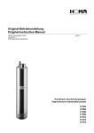
1
GB GB Operating Instructions SUBMERSIBLE CENTRIFUGAL PUMPS B80 Series HME KME Readthisoperatinginstructionsbeforestartup! Toberetainedforfuturereference. 1 GB GB Table of contents 1. Safety ............................................................................................................................................................... 4 1.1 Personnel responsible for installation and start-up................................................................................................. 5 1.2 Personnel responsible for operation and maintenance........................................................................................... 5 1.3 Personnel responsible for repairs.......................................................................................................................... 5 1.4 Improper use....................................................................................................................................................... 6 1.5 Disposal.............................................................................................................................................................. 6 2. General ............................................................................................................................................................... 7 2.1 Field of application ............................................................................................................................................. 7 2.2 Construction....................................................................................................................................................... 8 2.3 Application limits................................................................................................................................................. 8 2.3.1 Ambient temperature .............................................................................................................................. 8 2.3.2 Maximum temperature of pumped liquid.................................................................................................... 8 2.3.3 Immersion depth....................................................................................................................................... 9 2.3.4 Solids....................................................................................................................................................... 9 2.3.5 Specific gravity......................................................................................................................................... 9 2.3.6 Kinematic viscosity.................................................................................................................................... 9 2.3.7 Vapour pressure........................................................................................................................................ 9 2.3.8 Minimum delivery rate............................................................................................................................... 9 2.3.9 External flushing....................................................................................................................................... 9 2.4 Motor ............................................................................................................................................................. 10 2.4.1 Electrical connections . ........................................................................................................................... 10 2.4.2 Protection level....................................................................................................................................... 10 3. Installation and operating instructions........................................................................................................................ 11 3.1 Transport.......................................................................................................................................................... 11 3.2 Storage............................................................................................................................................................. 11 3.3 Installation........................................................................................................................................................ 11 3.4 Start-up............................................................................................................................................................ 14 3.5 Operation.......................................................................................................................................................... 15 3.6 Disassembly..................................................................................................................................................... 16 3.7 Maintenance..................................................................................................................................................... 17 3.8 Repairs............................................................................................................................................................. 17 4. Malfunctions and possible causes.............................................................................................................................. 18 5. Technical data.......................................................................................................................................................... 19 6. Dimensions.........................................................................................................................................................20/21 Declaration of conformity................................................................................................................................................ 23 Note: In the operating instructions figures are mentioned in brackets. These refer to the item specifications in the spare parts list of the respective model. GB 1. Safety These operating instructions: • must be considered as part of the product. • must be read by the operator of the pump before placing it into operation and must be followed during operation. • must be given to any subsequent owners or users of the product. • must be updated by the user for any addendum received. Warning! Chemical hazard! These pumps have been designed to deliver a variety of liquids and chemicals. Please heed the notes regarding disposal when performing maintenance and repairs. Warning! Safety risks for personnel mainly arise from improper use or accidental damages. These risks may be of an electrical nature as far as the non-synchronous motor is concerned and may cause injury to hands if working on an open pump. Risks may also arise due to the nature of the liquids pumped. It is therefore of utmost importance to closely follow all the instructions contained in this manual so as to eliminate the causes that may lead to pump failure and the consequent leakage of liquid dangerous for both personnel and the environment. Risks may also arise from improper maintenance or dismantling practices. In any case five general rules are important: A) all services must be carried out by specialised personnel or supervised by qualified personnel depending on the type of maintenance required B) install protection guards against eventual liquid sprays (when the pump is not installed in remote areas) due to an accidental pipe rupture. Arrange for safety basins to collect possible leakage C) when working on the pump always wear acid-proof protective clothing D) arrange for proper conditions for suction and discharge valve closing during disassembly E) make sure that the motor is completely disconnected during disassembly Proper design and building of the plants, with well positioned and well marked piping fitted with shut-off valves, adequate passages and work areas for maintenance and inspections are extremely important (should the plant be faulty constructed or present wearand-tear defects, the pressure developed by the pump could lead to failure). It must be stressed that the major cause of pump failures leading to a consequent need to intervene is due to the pump running dry in manually operated plants. This is generally due to: • the suction valve being closed at start-up or • the suction tank being emptied without stopping. GB 1.1 Personnel responsible for installation and start-up Interventions allowed only to specialised personnel who may eventually delegate to others some operations depending on specific evaluations (technical capability required: specialisation in industrial plumbing or electric systems as needed). 1.2 Personnel responsible for operation and maintenance Permissible actions for general operators (after receiving instruction in correct use of the system): • Starting / stopping the pump • Opening / closing the valves after the pump has been switched off • Emptying and cleaning the housing through valves and pipes intended for this purpose • Cleaning the filter elements Actions that may be performed by trained personnel (technical abilities required: general knowledge of the mechanical, electrical and chemical condition of the system being supplied by the pump and of the pump itself): • Checking the surrounding conditions • Checking the condition of the liquid being pumped • Checking the stop / approval devices • Checking the rotating parts of the pump • Determining the existence of malfunctions 1.3 Personnel responsible for repairs Actions that general operators may perform under the supervision of qualified personnel: • Stopping the pump • Closing the valves • Emptying the pump casing • Loosening the pipe connections • Loosening the fixing screws on the base plate • Cleaning with water or a suitable solvent • Transport (after the electrical leads have been disconnected by qualified personnel) Actions that may be performed by trained personnel (technical abilities required: Knowledge of mechanical operations, the ability to prevent damage during handling due to rubbing or impact, technical knowledge regarding fastening of screws and bolts on various materials such as plastic/metal, use of precision measuring instruments: • Opening and closing the pump casing • Removing and replacing of rotating parts GB 1.4 Improper use The pump is to be used solely to deliver liquids. The pump cannot be used to generate isostatic or counter pressures. The pump must not be used to mix liquids that undergo exothermic reactions. The pump must be installed vertically in a stationary position. The pump must be connected at the pressure port to a suitable hydraulic system with appropriate piping. A shut-off mechanism independent of the pump must be installed in the system. Handling of chemically aggressive liquids requires specific knowledge. 1.5 Disposal Materials: Separate the plastic parts from the metal parts, and have them disposed of by an authorised company. GB 2. General 2.1 Field of application Series B80 pumps are designed and built to transfer liquid chemical products with a specific gravity, viscosity, temperature and stability of state appropriate for use with centrifugal pumps in a fixed installation, from a tank at a lower level to a tank or a pipe at a higher level. The characteristics of the liquid (pressure, temperature, chemical reactivity, specific gravity, viscosity, vapour pressure) and ambient conditions must be compatible with the characteristics of the pump and are defined when ordering. Impeller and static casings, in contact with the liquid, are constructed from thermoplastic materials; other parts in high chemical-resistant materials. The performance of the pump (pump capacity, delivery head and rpm) is defined upon ordering and specified on the identification plate. Series B80 HME and KME pumps are single-stage vertical centrifugal pumps. Series HME is equipped with a cantilever shaft at the bottom part. The pumps are directly immersed in the liquid to be pumped. They are connected by a rigid coupling to an electrical ansynchronous motor. The suction connection is axially facing downwards. The pressure connection is positioned laterally and, if requested, can be equipped with a discharge pipe for connection onto a piping (hydraulic) system outside of the tank. The support plate must be fastened to a rigid support structure (see installation instructions). Series B80 HME and KME pumps are not self-priming and, therefore, they must always be started with the body immersed. Once the pump has been started, the level must not drop below the minimum level in order to avoid the defusing of the pump. Series B80 HME and KME pumps can run dry occasionally when liquid is absent, but not for periods longer than 15 minutes; to resume pumping the pump body must be immersed. Clockwise rotation seen from the motor side. Make sure that the chemical and physical characteristics of the liquid have been carefully evaluated for pump suitability. The maximum pressure that the pump can be subjected to is 1.5 times the maximum prevalence value. The pump must not operate with the delivery closed The submerged part (liner) must not be subject to lateral hydrodynamic thrusts by the liquid mass being moved. The pump does not include any non return valve nor any liquid flow control or motor stop device. When calculating the head, consider the actual level of the liquid in the suction tank and not the outlet connection. GB 2.2 Construction The mechanical structure is extremely simple: the impeller is pulled in rotation by the pump shaft connected to the motor shaft by a rigid coupling; the counter rotation of the impeller and a labyrinth reduce fluid leakage towards the shaft; dynamic loads, usually reduced in this type of pump, are supported by the motor bearings. The pump is supplied with a base plate to fasten it to the supports that must be pre-mounted on the system. The discharge pipe, where it crosses the base plate, is provided with threaded collar (pipe clamp ring) and a lock nut which, by fastening it to the plate, prevents the volute casing from being affected by mechanical stress from the system. It is abosolutely necessary to reduce to a minimum any load on the connections. To do that, back the piping up with proper brackets in such a way to allow thermal expansions (e.g.: expansion coupling, proper configuration). The coated pump shaft, where it crosses the base plate, is provided with fume seal ring to protect the motor bearing and to reduce fume dispersion in the environment in case of hot liquids. 2.3 Application limits 2.3.1 Ambient temperature The range of permissible ambient temperatures depends on the type designation (specified on the identification plate): 0 - +40°C -10 - +40°C execution WR execution FC 2.3.2 Maximum temperature of pumped liquid The maximum temperature during continuous operation based on water depends on the type of materials chosen (see identification plate). 70°C 90°C execution WR execution FC GB 2.3.3 Immersion depth To prevent sludge collecting at the bottom of the tank, the immersion depth can be increased by adding a suction extension (in any case, ensure that the minimum distance from the bottom "S" is maintained). Should the extension pipe be greater than 250 mm in length, arrange for a bracket to keep lateral movement of the extension within 1 – 3 mm without blocking it whilst allowing for thermal expansion at the same time. The maximum length of the extension pipe is 500 mm. The nominal bore must be the same as that at the suction inlet. With an extension pipe installed, the level can drop below the impeller (pump casing) during operation (not during start-up) by the following amount based on water at a temperature of 25°C. 2.3.4 Solids The liquid being pumped may contain a maximum of 20 % of solid, non-abrasive particles not greater than 1 mm in size. The presence of fibrous, adhesive or abrasive substances is not allowed. The maximum allowed size of objects occasionally present is 3 mm. For pumps with an FC type designation, the maximum concentration of metallic particles is 0.5 %, provided that their size is less than 0.5 mm. Arrange for proper filtering or sedimentation stages to comply with the above-mentioned limits. 2.3.5 Specific gravity The specific gravity that can be pumped at a temperature of 25°C (for liquid and ambient) depends on the diameter of the impeller (shown on the identification plate) and the motor rating (shown on the motor identification plate) and has to be defined when ordering. 2.3.6 Kinematic viscosity The kinematic viscosity must not exceed 25 cSt so as not to significantly modify the performance of the pump. Higher values up to a maximum of 75 cSt are possible provided that the pump is equipped with a suitable impeller and motor (to be specified when ordering). 2.3.7 Vapour pressure The vapour pressure value of the liquid to be pumped must exceed (by at least 1.5 m w.c.) the difference between the absolute total head (suction-side pressure plus positive pressure head, or minus suction lift) and the pressure drops in the suction-side piping (including the pressure drops across filters and the inlet NPSHr) drops shown on the specific tables. 2.3.8 Minimum delivery rate The pump must not be allowed to deliver less than 5% of the maximum delivery rate. 2.3.9 External flushing Flush out the pump at a flow rate of 100 l/h at a pressure of 1.5 bar. GB 2.4 Motor 2.4.1 Electrical connections The pump’s direction of rotation, which can be verified by observing the cooling fan (in B80 pumps, the cooling fan must rotate clockwise when viewed from above) is determined by the electrical connection to the terminals. With single phase motors the direction of rotation may be reversed by changing the position of the connection plates: With three-phase motors the direction of rotation may be changed by swapping any two of the three conductors independently of the type of connection to the windings: The windings of three-phase motors ( e.g. with (a) 230-400 V; (b) 400-690 V) require a delta-connection for lower voltage ( 230 volts for a ; 400 volts for b). They require a star-connection for higher voltage (400 volts for a; 690 volts for b). Star/delta starting is used when the motor is rated above 7.5 kW (10 HP) only in the case of frequent starts and short running times, but always when the motor is rated above 15 kW (20 HP). This is done to safeguard the pump. 2.4.2 Protection level The initials IP are followed by two numbers : The first number indicates the level of protection against penetration of solid objects and in particular : 4 for solids whose dimension is greater than 1mm 5 for dust (eventual internal deposits will not harm operation) 6 for dust (no pentetration) The second number indicates the protection against the penetration of liquids. In particular: 4 for water sprays from all directions 5 for jets of water from all directions 6 for tidal and sea waves According to the IP protection indicated on the identification plate of the motor and to the environmental conditions, arrange for opportune extra protections allowing in any case correct ventilation and rapid drainage of rainwater. 10 GB 3. Installation and operating instructions 3.1 Transport •Cover the hydraulic connections. •When lifting the unit, do not exert force on the plastic hydraulic fittings. •Place the pump on its base or fixing plate during transport. •If the road is particularly rough, protect the pump by means of appropriate shock-absorbing supports. •Bumps and shocks may damage important working parts vital for safety and the functionality of the unit. 3.2 Storage 1) When it is necessary to store the pump prior to installation, don’t remove it from the original packaging. The packaged pump must be stored in an enclosed, clean and dry environment. 2) If the pump’s packaging seems damaged upon receipt, inspect the pump to check its integrity. Place it in new packaging for further storage. 3) Store the pump at an ambient temperature between -5°C and 40°C, and at a relative humidity below 80%. The packaged pump must not be subjected to shocks, vibrations or other loads. 4) Check the condition of the grease in the bearing casing (support) prior to installation, if the pump has been stored for more than 6 months. If necessary, add more grease. 3.3 Installation •Arrange for a particularly rigid support structure: maximum deflection must be less than 0.2 mm based on the pump weight at the installation site. •Paint the support structure with epoxy enamel or a similar material to prevent corrosion. •Arrange for adequate passage and install protective guards to protect personnel in compliance with applicable safety regulations. •For motors, provide additional protection in the case of outdoor installation. Ensure proper air flow to the motor fan wheel and that rainwater drains quickly. •The tank under the pump must be covered appropriately in the case of hot liquids or liquids generating corrosive fumes (damaging to metallic components of the pump outside the tank). Seal the base plate by means of thin, but not overly soft seals that are well compressed by the fixing bolts. •Do not use anti-vibration pads to mount the pump. •Anti-vibration joints are recommended at the outlet pipe connection. •Clean the system before connecting the pump. •Make sure that no foreign bodies are left in the pump. Remove the safety caps from the hydraulic ports. 11 GB Follow the instructions indicated in the following diagram: 1) 2) 3) 4) 5) 6) Install a shut-off valve on the discharge side. Install a check valve (particularly with vertical or horizontal pipe runs; mandatory when pumps are connected in parallel). Provide a connection point for a pressure gauge or safety pressure control device. Secure all piping firmly. Use expansion joints (indispensable with long pipe runs or hot liquids). Max. fluid speed on the pressure side: max. 3 m/s. Install 45° bends in the pressure line to facilitate pump installation and removal. Do not attach elbows (or other fittings) close to the pump (outlet or inlet). 7) Minimum suction head during start-up; for suction head during pumping, see "Application limits". 8) A vertical suction extension for bottom suction lift is allowed (Not in order to empty the container completely). 9) Use a foot strainer (3-5 mm mesh screen), if solid matter (open tanks) or coarse impurities are present. 10)Arrange for drainage of liquids from the base plate. 11)Use all of the fixing holes to install the pump. The fixing points must be kept at the same level. 12)Maintain the minimum distance "S" from the bottom and the walls (or other working pumps). 12 GB •Manually verify that all rotating parts are free to turn without abnormal friction by turning the fan wheel on the motor. •Make sure that the power supply matches the data shown on the pump motor identification plate. •Connect the motor to the power supply via a magnetic/thermal protective switch. •Install emergency stop devices to switch off the pump in case of low liquid level (floating, magnetic, electronic, pressure-sensitive). •Depending on the physical and chemical characteristics of the liquid to be pumped, the ambient temperature must not be higher or lower than the values stated under "Application limits". •Other enviromental conditions apply based on the IP type of protection of the motor. •Leave enough free space around the pump for a person to move. •Leave enough free space over the pump to permit lifting it. •Arrange for a rigid partition to separate the inlet ports in the case of pumps installed closed to each other. •The pump axis must not be positioned in the centre of small tanks. •Highlight the presence of aggressive liquids by means of coloured signs in compliance with applicable safety regulations. •Do not install the pump (made of thermoplastic material) close to heating sources. •Do not install the pump in areas subject to falling solid of liquid matter. •Do not install the pump in a potentially explosive atmosphere unless the motor and coupling have been provided for such an environment. •Do not use the pump to transfer flammable liquids. •Do not install the pump in close proximity to workplaces or crowded areas. •Install extra protective guards for the pump and personnel as the need arises. •Install an equivalent pump in parallel as a backup. 13 GB 3.4 Start-up •Verify that the instructions outlined in the installation section have been followed. •Verify the correct direction of rotation (clockwise as seen from the motor end) by supplying the motor with short impulses. •Ensure that the NPSH available is greater than that required by the pump (in particular with hot liquids, liquids with a high vapour pressure, if a long suction extension is used or in the case of negative suction head). •The suction pipe (if present) and the pump must be totally submerged. •Start the pump with the discharge valve partially closed. •Regulate the delivery rate by slowly opening the discharge valve (never by means of the suction valve) and make sure that the current draw (power consumption) of the motor does not exceed the rated value indicated on the motor identification plate. •Do not operate the pump at the limits of its performance curve: max. delivery head (discharge valve completely closed) or max. delivery rate (total absence of delivery flow and geodetic head on the delivery circulation). •Set the operating point to that for which the pump is intended. •Ensure that there are no abnormal vibrations or noise due to inadequate mounting or cavitation. •Avoid short and/or frequent starts by properly setting the control devices. Motor rating (kW) Max. starts/hour 0.75 - 1.5 36 2.2 - 4 28 5.5 - 7.5 20 11 - 15 15 18.5 - 30 10 37 - 110 6 Ensure that the temperature and pressure as well as the liquid characteristics are as specified at the time of order. 14 GB 3.5 Operation • Switch automatic control on. • Do not operate any valves whilst the pump is in operation. • Risk of dangerous water hammer effects in the case of sudden or improper valve actuation (only trained personnel should operate valves). • Completely empty and clean the pump before using a different liquid. • Isolate or empty the pump if the ambient temperature is the same or lower than the crystallisation temperature of the liquid. • Stop the pump if the liquid temperature exceeds the maximum allowed temperature indicated in the "Application limits" section. If the temperature exceeds this value by approx 20%, check the condition of internal parts. • Close the valves in case of leaks. • Wash with water only if compatible from the chemical point of view. As an alternative, use an appropriate solvent that will not undergo any dangerous exothermic reactions. • Contact the supplier of the liquid to be pumped for information on suitable fire-extinguishing measures. • Empty the pump in case of long periods of inactivity (in particular with liquids which would easily crystallise). 15 GB 3.6 Disassembly •All of the following maintenance operations must be performed under the supervision of qualified personnel. •Switch off power to the motor and disconnect the electrical leads. Remove the wires from the terminal box and cover the ends. •Close the pressure valves. •Wear gloves, safety goggles and acid-resistant clothing when detaching and washing the pump. •Loosen the lines and allow enough time for any remaining liquid to drain out of the pump. •Wash the pump before performing any maintenance work. •Do not contaminate the environment with the used washing liquid. •Lift the pump vertically, taking care to not exert any pulling forces on the immersion tube (column). •Before attempting to dismantle the pump, ensure that the leads have been disconnected from the motor and that the motor cannot be started accidently. Now open the pump, observing the sequence given in the spare parts list, and follow the recommendations below: •The nuts and bolts have right-hand threads. •To access the impeller, remove the volute casing unthreading the screws that fasten it to the column. Once the volute casing is open, the impeller must be disconnected, blocking the shaft on the opposite side (remove the motor fan if necessary); proceed by unscrewing the ogive (right thread), the impeller is then axially unthreaded. The shaft covering is axially unthreaded with the impeller. To remove the column and shaft complete motor: •Remove the locking screws of the half clamps (spare parts list pos.5) (see fig.1 below) •Remove the two half clamps (pos.4) (fig.1) •Unscrew the vapour seal counterface (pos.10) keeping the column locked (fig.2) •At this point, unthread the column •At this point, proceed with the removal of the shaft (unthread the locking screws of the rigid coupling (pos. 7)) or with the removal of the upper cover terminal. Alternatively, if it is only necessary to work on the electromotor The disassembly of the immersed parts can be avoided (fig. 3): •Remove the locking screws of the half clamps (pos.5) •Remove the two half clamps (pos.4) •Unthread the locking screws of the rigid coupling (pos. 7) Fig. 1 16 Fig. 2 Fig. 3 GB 3.7 Maintenance •All of the following maintenance operations must be performed under the supervision of qualified personnel. •Clean the filter elements regularly (every 2 - 30 days, depending on the liquid being pumped). •Inspect the rotating parts of the pump regularly (every 1 - 6 months, depending on the liquid pumped and the operating conditions). Clean, exchange or lubricate parts as necessary (see Recommendations). •Check for proper functioning of the motor controls regularly (every 3 - 5 months, depending on the liquid pumped and the ambient conditions). Proper operation of the controls must be assured. Efficiency must be guaranteed. •Excessive current draw (power consumption) could be an indication of impeller problems. •Unusual vibrations could be due to an unbalanced impeller (caused by damage or foreign bodies/deposits obstructing the blades). •Reduced pump performance could be due to an obstructed impeller or damage to the motor. •Motor damage could be due to abnormal friction within the pump. •Damaged parts must be replaced with new original parts. •The replacement of damaged parts must be carried out in a clean, dry area. 3.8 Repairs Before sending back the appliance, following must be observed: •Residuals in the appliance can cause danger to the environment and human health. The appliance must be completely emptied, rinsed and cleaned. •Please advise which liquid has been pumped. A respective safety data sheet must be attached to the return consignment. 17 GB 4. Malfunctions and possible causes The pump does not deliver: 01- Wrong direction of rotation 02- Suction piping is too long or has too many bends 03- Pump not completely flooded 04- Impeller blades obstructed by impurities 05- The check valve in the discharge pipe is blocked 06- The geodetic head of the system is greater than the maximum delivery head developed by the pump 07- The impeller is blocked by a considerable layer of crystals or as the result of melting due to dry running The pump has reduced capacity or insufficient pressure: see items 01, 02, 03, 04 08- The back pressure in the system is greater than that expected 09- Insufficient geodetic pressure head developed by the pump 10- Damaged or worn impeller 11- Friction bearing bushings (rotating bushing and guide bushing) worn (KME only) 12- Viscosity of liquid greater than that expected 13- Excessive amount of air or gas in the liquid pumped 14- Excessive amount of sludge in the liquid 15- Bends, check valves or other similar components close to the outlet 16- Liquid liable to turn to the gaseous state (particularly if hot or containing surface activ agents) The pump starts up regulary and then disconnects: 17- Make sure the minimum suction head is reached at the inlet port 18- Remove or shorten the suction extension pipe The current draw (power consumption) is too high: see items 12, 14 19- The delivery rate is greater than expected 20- The specific gravity of the liquid is greater than expected 21- Impurities inside the pump generate abnormal friction 22- The supply voltage is not the same as that on the motor identification plate The pump vibrates and is noisy: see items 11, 21 23- The pump is working at maximum delivery rate (no delivery head) 24- The pump and piping are not firmly secured 25- The supporting structure must be made more rigid. The pump shows signs of premature wear of internal parts: see items 14, 21 26- Liquid is overly abrasive 27- Frequent recurrence of cavitation (see items 02, 12, 15) 28- High tendency of the liquid to crystallise or polymerise during stand-by 29- Pump manufactured from materials not suitable for the liquid being pumped 30- Pump is being operated too far below pump capacity 18 kg kg kg m wc m³/h dB kg kW IEC n° V IP Weight pump (for H600; + 0.6 kg per 100 mm ea.) Weight motor Weight baseplate max. delivery head max. delivery rate Sound pressure level max. load on connection ports: F(x;y;z) Power Motor frame Phase Voltage Protection / 7 6 - 11 10.5 3 7 8 7 - 13,5 12.5 3 8 0,55 71B 0,37 71A / / - 17,5 14 3 10 0,37 71A 8 0,55 71B 10 0,75 80A Max. single strength value F (x,y,z) = 2 - 7 10.5 3 6 0,55 71B 14 10 - 22 17.5 3 14 6 16 S 14 N - 24 23.5 3 16 6 P 16.15 16 N - 28 25.5 3 23 6 P 16.20 32 S 400 ± 5% 50 Hz - 220 ± 5% 50 Hz Three-phase ( all versions) - AC-Current (<3 kW) 55 23 N - 40 22.5 3 32 10 P 20.20 55 S 32 N Max. single strength value F (x,y,z) = 2.5 23 S 1,5 90S 6 0,75 80A P 1,1 80B 5 1,1 80B 10.15 1,5 90S 5 0,75 80A N 2,2 90L 5 1,1 80B S 1,5 90S P 2,2 90L 10.10 3 100 N 2,2 90L S 3 100 P - 43 27.5 3 55 10 P 20.25 63 S 55 N - 46,5 34 3 63 10 P 30.25 / S 63 N - 50 40 3 / 10 P 30.30 4 112 06.10 3 100 N 4 112 S 5,5 132SA P 4 112 06.08 5,5 132SA N 7,5 132SB S 5,5 132SA P 7,5 132SB 04.08 / / N 7,5 132SB Version / / Type / S / / 5. Technical data GB 19 G3 G2 G1 G3 G2 G1 1 1/2" 32 40 40 40 06.10 10.10 10.15 16.15 16.20 1" 32 2" 2" 50 50 30.25 30.30 67 67 70 70 70 70 62 67 67 67 67 70 70 70 70 06.10 10.10 10.15 16.15 16.20 20.20 20.25 30.25 30.30 67 67 70 70 62 06.08 70 62 04.08 a1.1 2" 50 20.25 a1 2" 50 Range 1 1/2" 40 20.20 1 1/2" 1 1/2" 1 1/4" 1 1/4" 25 ANSI 06.08 ISO DnA 04.08 range Connections 160 160 160 160 130 130 130 130 100 100 100 h2 40 40 40 40 32 32 32 32 32 32 25 ISO 160 160 160 160 130 130 130 130 108 108 108 h2.1 1 1/2" 1 1/2" 1 1/2" 1 1/2" 1 1/4" 1 1/4" 1 1/4" 1 1/4" 1 1/4" 1 1/4" 1" ANSI DnM.1 96 96 96 96 75 75 75 75 53 53 50 Q 40 40 40 40 32 32 25 25 25 20 20 ISO 135 135 135 135 103 103 103 103 73 73 73 V 1 1/2" 1 1/2" 1 1/2" 1 1/2" 1 1/4" 1 1/4" 1" 1" 1" 3/4" 3/4" ANSI DnM.2 252 252 252 252 222 222 222 222 215 215 190 E 125 125 125 125 110 110 110 110 100 100 85 ISO KA 250 250 250 250 130 130 130 130 130 130 130 R min. 121 121 121 121 98 98 98 98 89 89 79 ANSI 89 89 89 89 89 89 98 98 98 98 100 100 100 100 100 110 110 110 110 H 79 85 ANSI KM.1 Flange 100 ISO HME 275 - 450 HME 450 20 KME 600 - 800 - 1000 - 1250 - 1500 6. Dimensions 70 79 79 79 89 89 98 98 98 98 B 310 310 310 310 310 310 310 340 75 85 85 85 100 100 110 110 110 110 A 400 400 400 400 400 400 400 450 450 450 340 340 340 70 75 450 ANSI ISO KM.2 30 30 30 30 20 20 20 20 20 20 20 C 18 x 4 18 x 4 18 x 4 18 x 4 18 x 4 18 x 4 18 x 4 18 x 4 18 x 4 18 x 4 14 x 4 ISO dxz 165 165 165 165 140 140 140 140 140 140 140 f 19 x 4 19 x 4 19 x 4 19 x 4 16 x 4 16 x 4 16 x 4 16 x 4 16 x 4 16 x 4 16 x 4 ANSI 220 220 220 220 190 190 190 190 190 190 170 g 18 x 4 18 x 4 18 x 4 18 x 4 18 x 4 18 x 4 18 x 4 18 x 4 18 x 4 18 x 4 14 x 4 ISO ANSI 390 390 390 390 340 340 340 340 340 340 340 m 16 x 4 16 x 4 16 x 4 16 x 4 16 x 4 16 x 4 16 x 4 16 x 4 16 x 4 16 x 4 16 x 4 dxz1 280 280 280 280 250 250 250 250 250 250 250 n 18 x 4 18 x 4 18 x 4 18 x 4 18 x 4 18 x 4 14 x 4 14 x 4 14 x 4 14 x 4 14 x 4 ISO ANSI 410 410 410 410 360 350 330 300 255 255 235 T max. 16 x 4 16 x 4 16 x 4 16 x 4 16 x 4 16 x 4 16 x 4 16 x 4 16 x 4 16 x 4 16 x 4 dxz2 G1 DeM.1 Thread G1 G1 G1 G 3/4 G 3/4 DeM.2 G 2 G 2 G 2 G 2 G 1 1/2 G 1 1/2 G 1 1/2 G 1 1/2 G 1 1/2 G 1 1/2 G 1 1/2 G 1 1/2 G 1 1/2 G 1 1/4 G 1 1/4 G 1 1/2 G 1 1/4 G 1 1/4 G 1 1/2 G 1 1/4 G 1 1/2 G 1 1/4 G 1 1/4 G 1 1/4 G 1 1/4 G 1 1/4 G1 DeA GB GB 21 GB 22 Lutz Pumpen GmbH Erlenstraße 5-7 D-97877 Wertheim Declaration of Conformity We herewith declare that the design and construction of the following machine in the versions marketed by us fully comply with the relevant basic safety and health requirements specified by the EC Directives listed. This declaration ceases to be valid if the machine is modified in any way without prior consultation with us. Type of device: Submersible Centrifugal Pump Model: B80 EC Directives: EC-Directive on machines (2006/42/EC annex I, section 1 without 1.2; such machines do not include commands/or start/stop controls) EC Directive on low voltage installations (2006/95/EC) EC Directive on electromagnetic compatibility (2004/108/EC) Person authorised to compile the technical file: Mr. Klaus Saemann, Lutz Pumpen GmbH, Erlenstraße 5-7, D-97877 Wertheim Wertheim, 29.12.2009 Jürgen Lutz, Managing Director GB Lutz Pumpen GmbH Erlenstraße 5-7 D-97877 Wertheim Tel. (93 42) 8 79-0 Fax (93 42) 87 94 04 e-mail: [email protected] http://www.lutz-pumpen.de Subject to technical changes. 06/10-2 24 Best.-Nr. 6999-551 Printed in Germany /Dru.