1
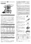
PARTS LIST/CARBURETOR
FIG DESCRIPTION
9290
A. CARBURETOR BODY
PN1113
B. CARB. ROTOR ASSY
PN1114
C. NEEDLE VALVE ASSY.
PN1115
D. SPRAY BAR ASSY.
PN1116
E. NEEDLE VALVE ONLY
PN1117
F. THROTTLE LEVER
PN1013
G. FUEL INLET ASSY.
PN1119
H. RATECHET SPRING
AA1181B
I. O RING SET
PN1118
J. THROTTLE-STOP SCREW SET
PN1014
K. SPARY BAR ONLY
AA1178
Congratulations on your purchase of a Thunder Tiger four-stroke
model engine. This engine represents the latest in Thunder Tiger
design and manufacturing techniques, employing advanced CAD
design and CNC manufacturing. All major components of Thunder
Tiger engines are machined from the highest quality materials in our
state-of-the-art manufacturing plant. Engines are then subjected to
rigorous quality control checks to ensure that your engine will provide
years of trouble free use.
F-54S / 9800
1.PROP LOCKNUT SET
PN0144
2.PROP WASHER
AA0026B
3.DRIVE WASHER
AA0477
4.CRANKCASE
AA0451
5.CRANKSHAFT
AA0454
6.BACKPLATE
AA0460
7.CONNECTING ROD
AN0458
8.WRIST PIN
AA0459
9.CIRCLIP
AA0327
10.PISTON
AA0456
11.PISTON RING
AA0457
12.CYLINDER
AA0455
13.CAMSHAFT
AA0462
14.CAMSHAFT COVER SET
PN0145
15.CAM FOLLOWER SET
PN0146
16.PUSH ROD SET
PN0147
17.PUSH ROD COVER ASSEMBLY
PN0148
18.CYLINDER HEAD
AN0452
19.CYLINDER HEAD (W/VALVE ASSEMBLYLY)
PN0149
20.INLET VALVE
AA0474
21.EXHAUST VALVE
AA0475
22.VALVE SPRING SET
PN0150
23.SPRING RETAINER SET
PN0151
24.SPRING HOLD COLLARS
PN0152
25.ROCKER ARM SET
PN0153
26.ROCKER ARM SUPPORT SET
PN0154
27.ROCKER ARM COVER
AA0453
28.INLET PIPE
AA0476
29.EXHAUST PIPE SET
PN0155
30.BREATHER NIPPLE
PN0131
31.GASKET SET
PN0156
32.CRANKSHAFT BEARINGS(FRONT)
AMV608Z
33.CRANKSHAFT BEARINGS(REAR)
AMV16001
34.CAMSHAFT BEARING
AMV695ZZ
35.HEAD SCREWS SET
PN0157
36.CRANKCASE SCREWS SET
PN0158
37.CARBURETOR BOLTS SET
PN0159
38.CRANKSHAFT KEY SET
PN0160
39.MUFFLER ASSEMBLY
9220
40.CARBURETOR ASSEMBLY
9290
41.CHOKE VALVE ASSEMBLY
9292
IMPORTANT
THUNDER TIGER MODEL CO.
No. 7, 6th ROAD INDUSTRY PARK
TAICHUNG TAIWAN R.O.C. 407
JA0262 Made in Taiwan R.O.C.
THUNDER TIGER U.S.A. Inc.
ATT: SERVICE DEPARTMENT
2430 LACY LANE, SUITE 120
CARROLLTON, TX 75006
SPECIFICATIONS
Engine
Displacement
Stroke
Bore
Practical R.P.M.
Output Power
Weight (w/muffler)
F-54S
8.86 c.c / .541 cu.in.
19.6 mm / 0.7765 in.
24.0 mm / 0.9448 in.
1,800 ~ 12,5000 rpm
0.9 HP /12,000 rpm
430 g /15.2 oz.
NECESSARY ACCESSORIES
INSTRUCTION
PARTS LIST/ENGINE
FIG DESCRIPTION
THUNDER TIGER F-54S 4 STROKE
ENGINE OPERATING INSTRUCTIONS
This engine will provide you with years of safe use, provided that you
carefully follow these safety instructions:
1. This model engine IS NOT A TOY, but a powerful miniature
engine that is capable of inflicting damage to both people
and property if misused.
2. Always mount the engine securely in a test stand or highquality engine mount. Never, ever attempt to clamp your
engine in a vise.
3. When operating your engine keep all spectators at least 20
feet away.
4. Make sure that you use the correct propeller for your engine.
Specific recommendations are listed in this manual.
5. Make sure that the propeller nut is securely fastened before
each flight.
6. Keep yourself away from the path of the propeller when running
your engine.
7. Keep your hands away from the propeller. Always use a
"chicken stick" or electric starter to start your engine.
8. Make all adjustments to the engine and carburetor from
behind the propeller.
9. Never use your hands or any other part of your body to stop
the propeller. Do not throw any object into the propeller to
stop the engine. Cut off the fuel supply by removing the fuel
line, pinching it closed, or closing the throttle barrel
completely.
10. Never use a propeller that is cracked, nicked or damaged in
any way.
11.It is recommended that you wear safety glasses when
operating any model engine.
12.Do not run your engine around dir t, sand or loose
gravel.Such material can be thrown into your eyes by the
propeller. In addition, the engine can be damaged by these
materials entering the carburetor.
13.Take care to keep all loose clothing, rags, tools, etc. away
from the propeller.
14.Keep all fuel lines, glow clips, etc. away from the propeller.
15.Take care when handling your engine after running. Model
engines get very hot during operation!
16. Always operate your engine with proper ventilation. Model engines
produce toxic fumes when run in a closed room or confined area.
The following items are necessary for operating your engine, and are
available from your local hobby supplier.
Fuel
A good quality, commercially available fuel containing 30% oil and 1015% nitro is recommended for use in Thunder Tiger four-stroke
engines. Fuels containing a blend of both castor and synthetic oil is
best. Fuels containing only castor oil are not recommended! (But during
the breaking-in period, it is better for the fuel containing at least 20%
lubrication oil.)
Glow Plug
Due to the mechanics of the four stroke engine, one explosion every
two revolutions, are difference with the two stroke engine. So the
special type plug should be choosed to fit the four stroke engine. The
type and quality of glow plug used in your engine will have a major
impact on overall performance and reliability. For Thunder Tiger fourstroke engine,we recommend the following plugs: Thunder Tiger Super 4-T #9283, O.S.- type-F, Saito- P-1, Hangar 9 # 3010 and McCoy
- MC-4C.
Glow Starter
The electric power source for heating the glow plug. This can be a
simple 1.5v Hobby Battery with a locking socket (TTR 2176) or a selfcontained, rechargeable unit such a TTR 2170.
Plug Wrench
Used for tightening the glow plug as well as the propeller nut. TTR
1102 4-way wrench is recommended.
Fuel pump or bottle
Required to fill the fuel tank in your model. A Thunder Tiger hand-crank
pump (TTR 1645) or 12v electric pump (TTR 1658) are available from
your hobby dealer.
Chicken Stick/ Safety Stick
Used to flip the propeller when starting the engine by hand. NEVER
use your fingers to start a model engine!
Electric Starter
An electric starter is an easy way to start your Thunder Tiger engine.
Used with a 12 volt battery, it is the safest and most convenient starting
method.
Propeller
Suggested propeller sizes are shown in the table below, with
allowances for different types of aircraft and performance goals. Keep
in mind that factors such as aircraft weight, size, style and type of flying
will affect your choice of props. After break-in, select the optimum prop
size by practical flying tests. Begin your tests with the suggested
propeller sizes in the table below:
Engine
F-54S
Breaking-in
11x5
Stunt
10X9,10X10,11X5,
11X6,11X7,11X8
Caution: It is very important to use a well balanced propeller and
spinner only. An unbalanced propeller or spinner can cause substantial
damage to both the aircraft and engine.
Fuel Tank
Choose the proper fuel tank as recommended by the manufacturer of
your airplane kit. Thunder Tiger has a series of new tanks that are
available at your hobby dealer.
Fuel Line
Choose a high quality, silicone fuel line for use with your Thunder Tiger
engine.
INSTALLATION OF THE ENGINE
Mount your engine securely to
rigid hardwood rails (e.g. maple)
or a radial engine mount of metal
or glass-filled nylon composition.
The top surfaces of the motor
mount must be absolutely flat
and parallel to avoid crankcase
distortion and stress. Be sure to
use only the highest quality
mounting hardware such as
hardened steel screws, etc. In
order to reduce engine noise, a
flexible engine mount can also
be used. The outside dimensions
of this engine are shown at
FIG.1.
Fuel Tank
The fuel tank should be mounted
as close to the engine as
possible. Ideally, the center line of the tank should be level with the
needle valve. The design of your aircraft will determine the actual tank
location, but use the above instruction as a guide. Keep in mind that
tank location can have a major impact on engine performance. Make
sure that your entire fuel system is sealed and well constructed to
eliminate the possibility of fuel or air leakage. If possible, wrap your fuel
tank with high quality foam rubber to reduce fuel foaming from airframe
vibration.
Glow Plug
Use a 4-way wrench to insert the glow plug into your engine. Be careful
not to use excessive force, but make sure the plug is tight and the
copper washer is properly sealed beneath the glow plug.
Muffler
After the engine is mounted in your model or test stand, secure the
muffler to the exhaust pipe. Screw the exhaust pipe into the cylinder
head at the desired angle and secure with the jam nut.
Propeller
Mount the suitable propeller securely to your engine. If using a spinner,
make sure that the cut-out area for the propeller blades offer adequate
clearance so that no part of the prop is touching the spinner.
Caution: If a four-stroke engine is run too lean or under excessive
loads, pre-ingitation occurs in the combustion chamber (called
"knocking" or "detonation"). This condition will cause an unuaual
vibration in the engine, and could possibly cause engine damage! The
biggest danger, however, is that this vibration offten loosens the prop
nut and sends the propeller flying off the engine. Make absolutely
certain that the prop nut is fastened securely!
BREAK-IN THE ENGINE
Proper break-in is critical to the life of any model engine. During this
period, the precision metal parts of the engine are properly mated and
worn in. It is critical that the engine be run in an area free from
excessive dirt and sand. Your engine may be broken-in on a test bench
or in your model. Either method is fine, however a test bench allows
you to keep the engine away from dirt as well as making adjustments
simpler.
Break-in checklist:
a. Use the proper fuel and glow plug as described in NECESSARY
ACCESSORIES.
b. Select the proper propeller as recommended in the propeller
chart.
c. Make sure that the high-speed needle valve is opened 2-2
1/2 turns.
d. We strongly recommend the use of a tachometer when
tuning a four-stroke engine. Although the carburetor
adjustments are the same, four-stroke engines cannot be
tuned by sound like a 2-stroke. Use of a tachometer will
eliminate the possibility of damaging your engine by running
it too lean.
Starting the Engine
a. Make sure that the glow plug and propeller are installed and properly
tightened.
b. Be sure that the fuel lines are properly connected, with the
fuel pick-up connected to the carburetor and the pressure
line connected to the muffler pressure nipple.
c. Make sure that the muffler is properly installed.
d. Fill the fuel tank.
e. Prime the engine using the following steps. (Make sure the
glow plug igniter is NOT connected!)
1. Open the carburetor to full throttle.
2. Close the choke valve.
3. Rotate the prop counter-clockwise by hand 7 or 8 revolutions, or until
you notice fuel draining from the carb.
f. Open the choke valve.
g. Adjust the throttle to 25% open.
h.Rotate the prop clockwise until you feel the prop hit the
compression stroke.
i. Connect the glow plug igniter.
j. Start the engine counterclockwise using an electric starter or
"chicken stick".
Caution: When using an electric starter, never attempt to start a
flooded engine. Although the electric starter may turn the engine over, it
can damage the connecting rod or other components. If the engine
becomes flooded, simply remove the glow plug and turn the engine
over with the electric starter or "chicken-stick". The excess fuel will be
forced out the glow plug hole.
During Break-In:
a. Do not exceed 5,000 R.P.M. during the first five minutes of
operation.
b. Because of the extremely rich needle setting used during
breaking-in, you may wish to keep the glow plug igniter
attached.
c. After consuming the first tank of fuel, allow the engine to
cool. You can then re-start the engine and gradually lean the
needle setting during the next few tanks.
d. During the third tank of fuel, lean the needle valve for
optimum R.P.M. using the tachometer, then richen the
mixture until a drop of 200-300 R.P.M. occurs.
CARBURETOR ADJUSTMENTS
The air-bleed carbruetor with a throttle rotor and an air-bleed screw
provides a wide range of engine speed control from idling speed to full
power. The throttle rotor with the throttle lever linked to a servo under
the control of R/C system in your model will enable engine speed to be
varied. As the carburetor of your engine has been factory set for
approximate the best running with fuel tank is correctly located as
previously described, it should not be required to adjust anything
except the needle valve. After the engine has been broken-in, check
the operation of the throttle according to the following and re-adjust the
air-bleed screw when necessary.
THROTTLE-STOP SCREW ADJUSTMENT
1) Start the engine and open the throttle fully.
2) Adjust the needle valve to the best position.
3) Close the throttle gradually from the highest speed to the
lowest possible.
4) Find and fix the idling position where the lowest possible
R.P.M. with steady running is obtained by means of the
"throttle trim" on your transmitter or by screwing the throttlestop screw without risk of the engine stopping.
5) Open the throttle fully and make sure that the engine runs at
the highest speed, or else (i.e. your engine stops) re-set the
idling position at a little higher R.P.M..
6) Keep running at the highest speed for about 10 seconds,
then close to the lowest speed abr uptly. Run at idling for
about 5 seconds and make sure it does not stop, or else reset the idling position at a little higher.
7) Repeat the procedure 5) abruptly, then the procedure 6) for
few times to ensure the best running is obtained. If your
engine stop in the middle range or it is not the best to speed
up from idling to full power, please adjust the air-bleed screw
as follows:
AIR-BLEED SCREW ADJUSTMENT
1) Start the engine and open the throttle fully.
2) Adjust the needle valve to the best position.
3) Close the throttle gradually from the highest speed to the
lowest possible.
4) Find and fix the idling position where the lowest possible
R.P.M. with steady running is obtained by means of the
"throttle trim" on your transmitter or by screwing the throttlestop screw without risk of the engine stopping.
5) In order to determine which way to adjust, determine firstly
the present condition of the idle fuel mixture. Hold your
aircraft with arms as illustrated and nose up approximate 15 slowly.
CONDITION 1
If the engine runs unevenly or stops, nose down your aircraft
immediately approximate 15 . The engine should run steadily. Stop
the engine by pinching the fuel line and close (clockwise) the air-bleed
screw about 1/2 turn. These adjustment can be made without stopping
the engine. However, it is advisable for beginners to stop the engine for
safety reasons.
CONDITION 2
If the idling runs up, stop the engine and open the air-bleed screw
about 1/2 turn.
6) Re-start the engine, and repeat from the procedure 3) to 5) until a
steady idle is obtained.
NOTE
After the needle valve is adjusted on procedure 2), do not attempt to
adjust it again.
?W26X?hg
?7<B1?hg
?@e@?hg
?3=C5?hg
?V40Y?hg
?W2@6X
?7<?B1
?@e?@
?3=?C5
?V4@0Y
Installation of the Camshaft
The position of the camshaft determines the timing of your engine. An
improper camshaft position will cause serious engine damage even
engine may not be start. It is strongly suggested that you Do Not
Dismantle the camshaft . If for some reasons, you need to
disassemble or change the camshaft and as you re-install the
camshaft, please follow the following procedures :
a. Turn the crankshsft to the T.D.C. (top dead center). (There is
a T.D.C. mark on drive washer, set this mark on the top
position.)
b. Apply some light oil (3-in-1, Mystery oil. etc.) to the camshaft.
c. Note that there is a mar k on the side surface of the gear.
When re-installing the camshaft, the mark must point to the
upside cam cover screw hole. ( Refer to FIG.3.)
d. Install the cam cover and properly secure the two screws.
e. Rotate the crankshaft several revolutions to insure the
camshaft is properly seated, then reassemble the rest parts
of the engine.
ENGINE CARE
Always keep the outside of your engine clean. Use clean, fresh fuel and
keep your fuel can, pump, and fueling system free from dirt particles.
Install a fresh filter between the fuel tank and carburetor, and between
your fuel pump and filling line to prevent any dirt from entering your
engine.
Model fuel contains alcohol, which is hydroscopic (meaning that it
attracts moisture from the atmosphere). This can cause corrosion to
the internal engine parts. After each flying session, run all the fuel out
from inside the engine and disconnect the fuel line from the carburetor.
Put 4 or 5 drops of after-run oil (Marvel Mystery Oil, Prather, Pacer,
etc.) into the carburetor and turn the engine over several times by hand
to protect the engine bearings and internal parts from corrosion.
The use of after-run oil is also important during periods of prolonged
storage (such as winter).
We suggest removing the engine from the model, liberally applying oil
into the carburetor and glow plug hole, and wrap your engine in a soft
cloth and store in a sealed plastic bag.
If you choose to store your engine in the airplane, make sure to store
the model with the engine down so as to keep the bearings lubricated.
Do not dismantle your engine unnecessarily, as this may upset
precision fits such as piston/cylinder and valve/tappet assemblies. If it
is necessary to completely clean your engine, remove only the
carburetor (do not disassemble), muffler and exhaust pipe. Flush the
entire engine with fresh fuel and reassemble.
Valve Clearance Adjustment
The valve clearances on your engine are factory set and will seldom
require adjustment. However, after a considerable amount of running
time you detect a loss of power, or if the engine must be disassembled
after a crash, the valve clearances should be checked and adjusted.
The valve adjusting kit , containing two gauges and one wrenche, are
enclosed in the box.
Note: Valve clearances MUST be checked when the engine is COLD.
a. Remove the rocker arm cover.
b. Turn the propeller until you feel compression, then turn it an
additional 1/4 turn and stop. Both valves should be closed
now.
c. The required valve clearance is .03mm - 0.10mm (.0012 .004) measured between the valve stem and rocker arm. A
.03mm shim should pass through the gap, 0.10mm should
not. (Refer to Fig.2)
Caution: Incorrect valve clearances can cause difficult starting, erratic
operation and loss of power.
THUNDER TIGER 3 YEARS LIMITED WARRANTY
Your engine is guaranteed to be free from defects in materials and
workmanship for a period of 3 years from the date of purchase when
returned for service accompanied by proof of purchase (register
receipt, credit card invoice, etc.). Crash damage or problems caused by
improper use are specifically not covered under this warranty. Damage
caused by customer disassembly, use of improper or substandard fuel,
use of improper accessories (such as propellers, glow plugs, etc.) or
any use of product other than its specific intended use will
automatically void this warranty.
SERVICE PROCEDURES
Should your Thunder Tiger engine require service, please follow the
following guidelines:
1. Do not return the engine to the place of purchase, as they are not
authorized or equipped to perform service.
2. Remove the engine from the model. We cannot accept equipment
for service other than engine.
3. Along with your engine and proof of purchase, enclose a complete
written explanation detailing the problem(s) with your engine. Be
sure to include your name, address and daytime telephone number.
4. For repairs not covered under warranty, the charges will be billed to
you C.O.D. Please mention if you wish to have an estimate of nonwarranty repair charges prior to us beginning service. (This may
cause a slight delay in your repair.)
5. For customers outside of the U.S. and Canada, contact the
authorized Thunder Tiger agent in your country.
6. For U.S. and Canadian customers, send your engine via insured
mail or U.P.S. to the Thunder Tiger Service Center. The address can
be found on a seperate sheet included with your engine.
TROUBLE SHOOTING GUIDE
SYMPTOM
Engine will not fire
Engine fires but will not run
CAUSE
discharged starting battery
Over primed Incorrect glow plug
CORRECTIVE ACTION
Low voltage or Replace/recharge starting battery
Disconnect battery and rotate prop several times to
clear engine, Verify plug type
Engine starts but slows down then stops
Mixture too rich
Close needle valve 1/4 turn until engine runs smoothly
Engine starts,speeds up,then stops
Mixture too lean
Open needle valve 1/4 turn until engine runs smoothly
Engine quits when starter battery is removed
Mixture too rich, Incorrect glow plug, Improper or bad fuel
Close needle valve 1/4 turn and restart
Change glow plug, Change fuel