1
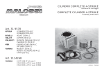
Manuale di installazione M200-DI
M200-DI Installation manual
ENGLISH VERSION AT PAGE 7
SOMMARIO
1.0 AVVERTENZE GENERALI........................................................................... pag.
2
2.0 CONTENUTO DELL’IMBALLO .................................................................... pag.
2
3.0 CARATTERISTICHE TECNICHE ................................................................. pag.
2
4.0 ISTRUZIONI DI MONTAGGIO ...................................................................... pag.
4.1 DESCRIZIONE DELLE CARATTERISTICHE ...................................... pag.
4.2 FUNZIONI BASE .................................................................................. pag.
4.3 FUNZIONAMENTO ............................................................................ pag.
3
3
3
4
5.0 PROGRAMMAZIONE ................................................................................. pag.
5
6.0 SCHEMI ELETTRICI .................................................................................... pag.
6
1.0 AVVERTENZE GENERALI
Per evitare malfunzionamenti del commutatore si consiglia di:
Passare i fili del commutatore il più lontano possibile dai cavi dell’alta tensione.
Fare delle buone connessioni elettriche evitando l’uso dei “rubacorrente”.Si tenga presente
che la migliore connessione elettrica è la saldatura debitamente isolata.
Si sconsiglia vivamente di sostituire il fusibile da 5 A con fusibili di amperaggio maggiore
o non conforme alle norme DIN 72581, ciò può provocare danni irreparabili.
Non aprire per nessun motivo la scatola del Commutatore, soprattutto con il motore in
moto o il quadro inserito.
ATTENZIONE
SI DECLINA OGNI RESPONSABILITÀ PER DANNI A COSE E PERSONE, DERIVATI
DALLA MANOMISSIONE DEL PROPRIO DISPOSITIVO DA PARTE DI PERSONALE NON
AUTORIZZATO E DALL’INOSSERVANZA DELLE AVVERTENZE.
2.0 CONTENUTO DELL’IMBALLO
La confezione è composta da:
N° 1 commutatore,
N° 1 staffa per il fissaggio del commutatore,
N° 1 cablaggio,
N° 1 istruzione di montaggio,
N° 1 sacchetto accessori.
3.0 CARATTERISTICHE TECNICHE
Tensione d’alimentazione
Corrente nominale uscita GAS (filo BLU)
Corrente nominale uscita BENZINA (filo GIALLO)
Fusibile a norme DIN 72581
Ingombri scatola Commutatore
Il prodotto è conforme alle seguenti normative:
2
10÷16 Vdc
5 A max.
5 A max.
5 A max.
altezza 24 mm
profondità 77 mm
larghezza 35 mm
regolamento ECE 67/01
regolamento ECE 110/00
regolamento 2006/28/CE
4.0 ISTRUZIONI DI MONTAGGIO
4.1 Descrizione delle caratteristiche
LED
GIALLO
LED
VERDI
PULSANTE DI
COMMUTAZIONE
LED BICOLORE
ROSSO/VERDE
-
Utilizzo su vetture ad iniezione con riduttore elettronico,
Riprogrammabile,
Impostabile con avviamento a benzina e cambio in DECELERAZIONE o cambio in
ACCELERAZIONE.
Possibilità di utilizzo di diversi sensori di livello:
1050/806 (Lovato o AEB)
0÷4700 Ohm
0÷90 Ohm
Riserva
Regolazione della soglia di giri per la commutazione modificabile.
Il commutatore viene fornito programmato per funzionare con avviamento a benzina, commutazione in DECELERAZIONE e con sensore di livello tipo 1050.
4.2 FUNZIONI BASE
DISPOSITIVO DI SICUREZZA
Safety-Car incorporato per l’abilitazione delle elettrovalvole del GAS solo con motore acceso
necessario al blocco automatico dell’erogazione del GAS entro 1 secondo dallo spegnimento
dell’autovettura.
INSTALLAZIONE
Possibilità d’installazione tramite apposita staffa di sostegno inclusa nella confezione.
Possibilità d’installazione ad incasso nel cruscotto, tramite apposito tranciante termico (da
richiedere a parte).
N.B.: Il commutatore è fornito privo di sensori, quindi per ottenere l’indicazione del livello carburante si deve richiedere a parte l’apposito sensore (METANO o G.P.L).
3
4.3 FUNZIONAMENTO
AVVIAMENTO A BENZINA E CAMBIO IN DECELERAZIONE
FUNZIONAMENTO A GAS
Avviamento a BENZINA con passaggio automatico a GAS.
In commutazione, il LED GIALLO lampeggia mentre l’accensione
dei LED VERDI mostra la quantità di GAS; una volta raggiunto il
numero di giri prestabilito, in fase di DECELERAZIONE, si ha il
passaggio da BENZINA a GAS (se in RISERVA, lampeggia solo il
LED GIALLO).
AVVIAMENTO A BENZINA E CAMBIO IN ACCELERAZIONE
FUNZIONAMENTO A GAS
Avviamento a BENZINA con passaggio automatico a GAS.
In commutazione, il LED GIALLO lampeggia mentre l’accensione
dei LED VERDI mostra la quantità di GAS; una volta raggiunto
il numero di giri prestabilito, in fase di ACCELERAZIONE, si ha
il passaggio da BENZINA a GAS (se in RISERVA, lampeggia
solo il LED GIALLO).
Tramite la pressione del pulsante si selezionano le seguenti modalità:
FUNZIONE DI EMERGENZA
Avviamento direttamente a GAS.LED GIALLO e LED VERDI
accesi in base alla quantità residua di GAS (in RISERVA, s’accende solo il LED GIALLO).Dopo l’inserimento del sotto chiave
e in assenza dei giri motore, mantenendo premuto il pulsante per
3 secondi, si entra in condizioni d’emergenza: il LED ROSSO è
spento, il LED GIALLO acceso fisso mentre i LED dell’indicatore
mostrano la quantità di GAS. Appena compaiono i giri motore
(anche se non si supera il valore di riferimento per il cambio) la
vettura parte direttamente a GAS.
FUNZIONAMENTO A BENZINA
LED BICOLORE acceso ROSSO.
4
5.0
PROGRAMMAZIONE
Per modificare il settaggio del commutatore, seguire le fasi descritte di seguito; si tenga
presente che, per portare a termine la programmazione in modo corretto, i passaggi elencati
devono essere eseguiti in sequenza. Nel caso in cui il pulsante non venga premuto nella giusta
sequenza e nelle tempistiche corrette, la procedura di settaggio verrà disattivata ritornando
all’impostazione precedente.
1. Connettere il commutatore. e girare la chiave d’accensione
su OFF.
2. Tenere premuto il pulsante sul commutatore.
3. Avviare l’autovettura.
4. Led bicolore (Rosso/Verde) lampeggiante.
5. Mantenere premuto il pulsante fino a quando il led lampeggia
solo Rosso
6. Rilasciare il pulsante; il led lampeggia Verde.
PROGRAMMAZIONE TIPO SENSORE DI LIVELLO
1. Premere il pulsante più volte fino ad ottenere la programmazione del sensore di livello desiderata.
LED GIALLO ACCESO: Sensore 1050/806
LED VERDE 1/4 ACCESO: Sensore 0÷4700 Ohm
LED VERDE 2/4 ACCESO: Sensore 0÷90 Ohm
LED VERDE 3/4 ACCESO: Sensore RISERVA
2. Tenere premuto il pulsante per 3 secondi per memorizzare e
passare al successivo settaggio.
PROGRAMMAZIONE CAMBIO IN ACCELERAZIONE O DECELERAZIONE
1. Led bicolore acceso VERDE.
2. Premere il pulsante fino ad ottenere la programmazione
desiderata.
LED GIALLO ACCESO:
LED VERDE 1/4 ACCESO:
Commutatore con cambio in
DECELERAZIONE
Commutatore con cambio in
ACCELERAZIONE
3. Tenere premuto il pulsante per 3 secondi per memorizzare e
passare al successivo settaggio.
PROGRAMMAZIONE SOGLIA GIRI PER LA COMMUTAZIONE
1. Led bicolore acceso ROSSO, il LED GIALLO indica l’impostazione della soglia di commutazione.
LED GIALLO ACCESO:
LED GIALLO LAMPEGG.:
giri motore maggiori del riferimento per il cambio
giri motore inferiori del riferimento per il cambio
Portare il motore al numero di giri a cui si vuole che avvenga la
commutazione; il LED GIALLO lampeggia se i giri motore sono
inferiori alla soglia, altrimenti rimane acceso. Ad ogni pressione
del pulsante, i giri motore (purchè non siano nulli) vengono
memorizzati come nuova soglia di commutazione.
Tenere premuto il pulsante per 3 secondi fino a quando il led bicolore lampeggia ROSSO/
VERDE. Spegnere la vettura.
5
6
INDEX
1.0 GENERAL RECOMMENDATIONS ............................................................ page 7
2.0 PACKAGE CONTENT ................................................................................ page 7
3.0 TECHNICAL SPECIFICATIONS ................................................................ page 7
4.0 ASSEMBLY INSTRUCTION MANUAL ...................................................... page
4.1
FEATURING DESCRIPTION .............................................................. page
4.2
BASIC FUNCTIONS ........................................................................... page
4.3
OPERATION ....................................................................................... page
8
8
8
9
5.0 PROGRAMMING ........................................................................................ page 10
6.0 WIRING DIAGRAMS .................................................................................... page 11
1.0 GENERAL RECOMMENDATIONS
To avoid any switch malfunctions we recommend to:
lay the switch wires as far as possible from the high-voltage cables.
Carry out some good electrical connections by avoiding the use of “power reducers”.
Keep in mind that the best electrical connection is a duly insulated welding.
We recommend not to replace the 5 A fuse with higher amperage fuses not conforming to the DIN 72851 standard, as this could cause irrecoverable damage.
Do not open for any reason the switch box, mainly with running engine or switched-on
panel.
WARNING
WE REFUSE ANY RESPONSIBILITY FOR DAMAGE TO THINGS AND PERSONS
DUE TO THE TAMPERING OF THE DEVICE BY UNAUTHORISED PERSONNEL AND
TO THE LACK OBSERVANCE OF THE WARNINGS.
2.0 PACKAGE CONTENT
The package is made up of:
Nr. 1 switch,
Nr. 1 bracket for fixing the switch with fixing screws,
Nr. 1 SA022 wiring,
Nr. 1 assembly instruction manual,
Nr. 1 accessories bag.
3.0 TECHNICAL SPECIFICATIONS
Power voltage
Rated GAS output current (BLUE wire)
Rated GASOLINE output current (YELLOW wire)
DIN 72581 standard fuse
Overall dimensions of the switch box
The product conforms to the following standards:
7
10÷16 Vdc
5 A max.
5 A max.
5 A max.
height 24 mm
depth 77 mm
width 35 mm
rule ECE 67 R01
rule ECE 110 R00
rule ECE 2006/28/CE
4.0 ASSEMBLY INSTRUCTION MANUAL
4.1 FEATURING DESCRIPTION
YELLOW
LED
GREEN
LEDS
SWITCH
BUTTON
BICOLOUR
LED
-
To be used on cars with injection and electronic LPG or CNG reducer.
Reprogrammable,
Settable with gasoline starting and switching to gas while decelerating or gasoline
starting and switching to gas while accelerating .
Usable with different types on level indicators:
1050/806 (Lovato or AEB),
0÷4700 Ohm,
0÷90 Ohm,
Reserve.
Adjustable revolution reference for switching to gas.
The switch is delivered programmed with gasoline starting with switching to gas while decelerating and for 1050/806 type of level sensor.
4.2 BASIC FUNCTIONS
SAFETY DEVICES
The (built-in) Safety-Car enables the GAS solenoid valves only with running engine. This allows
the automatic locking of the GAS supply within 1 second after an accidental engine stop.
INSTALLATION
The switch is supplied without any sensors, therefore to obtain the indication of the fuel level
you must request the suitable sensor separately (C.N.G. or L.P.G.).
The switch can be built-in the instrument panel by inserting it in an existing opening or drilling
a hole by means of the suitable shears that can be supplied upon request;
alternatively, the package is supplied with a suitable supporting clip for fixing.
8
4.3 OPERATION
GASOLINE STARTING AND SWITCHING TO GAS WHILE DECELERATING
GAS OPERATION
Gasoline starting with automatic switching to gas.
When switching on, the YELLOW LED blinks while the GREEN
LEDs turn on to show the GAS quantity; after reaching the preset
RPM while DECELERATING, you shift from GASOLINE to GAS
(if you are in RESERVE, only the YELLOW LED blinks).
GASOLINE STARTING AND SWITCHING TO GAS WHILE ACCELERATING
GAS OPERATION
Gasoline starting with automatic switching to gas.
When switching on, the YELLOW LED blinks while the GREEN
LEDs turn on to show the GAS quantity; after reaching the preset
RPM while ACCELERATING, you shift from GASOLINE to GAS
(if you are in RESERVE, only the YELLOW LED blinks).
EMERGENCY FUNCTION
The car starts directly with gas fuel.
YELLOW LED on and GREEN LEDs on according to the
remaining GAS quantity (if it is in RESERVE, only the
YELLOW LED switches on).
After the 12 Volt ignition appears and in the absence of engine
RPM, by keeping the button pressed for 3 seconds you enter in
emergency condition: the RED LED is off, the YELLOW LED is
ON while the indicator LEDs show the GAS quantity. As soon as
the engine RPM appear (even if you do not overcome the reference value for the change), the car starts directly with GAS.
GASOLINE OPERATION
BICOLOUR LED on in RED.
WARNING
IN CASE THE COMMUTATOR IS PROGRAMMED TO
WORK WITH A RESERVE SENSOR, ONLY THE YELLOW AND THE FIRST GREEN LED WILL SWITCH ON
9
5.0 PROGRAMMING
1. Connect the switch.
2. Swicth on the car with the switch button pressed.
3. The bicolour LED is blinking,
4. Keep the switch button pressed until the bicolour LED will be
blinking only in RED.
5. Release the switch button. The bicolour LED will be blinking
in GREEN.
PROGRAMMING OF THE TYPE OF SENSOR
1. Press the button several times to obtain the programming of
desired level sensor.
YELLOW LED ON: 1050/806 level sensor
1ST GREEN LED ON: 0÷4700 Ohm level sensor
2ND GREEN LED ON: 0÷90 Ohm level sensor
3RD GREEN LED ON: RESERVE sensor
2. Hold down the button for 3 seconds to store and move to the
next setting.
PROGRAMMING OF THE CHANGE WHILE ACCELERATING OR DECELERATING
1. Bicolour LED on in GREEN.
2. Press the button several times to obtain the programming.
YELLOW LED ON:
1ST GREEN LED ON:
switch with change while DECELERATING
switch with change while ACCELERATING
3. Hold down the button for 3 seconds to store and move to the
next setting.
PROGRAMMING OF THE REVOLUTION REFERENCE FOR SWITCHING
1. Bicolour LED on in RED while the YELLOW led indicates
the setting of the switching revolution threshold
YELLOW LED BLINKING:
1ST GREEN LED ON:
engine revolution lower than
the reference for change
engine revolution higher
than the reference for
change
Start the car and bring the engine at the RPM at which you
wish the change will take place; the YELLOW LED blinks if the
engine RPM are lower than the switching reference, otherwise
it remains on. Whenever you press the button, the engine
RPM (provided they are null) are stored like new reference
for the change.
Hold down the button until the bicolour LED will be blinking RED/GREEN. Switch OFF the
car.
To carry out the programming correctly, the listed steps must be executed in sequence
10
11
LOVATO GAS S.P.A.
Strada Casale, 175 - 36100 Vicenza
Tel. +39-0444-218911 Fax +39-0444-501540
e-mail:[email protected] http:\\www.lovatogas.com
ISLOV725A-1