1
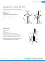
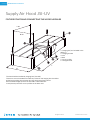
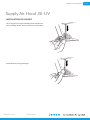
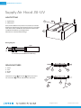
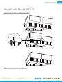
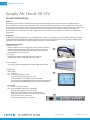
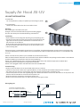
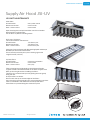
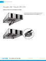
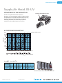
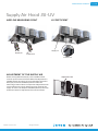
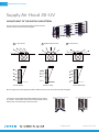
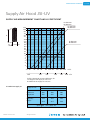
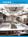
Supply air hood JSI-UV
Installation-, adjustment and user guide
WWW.JEVEN.COM
PAGE 2
JEVEN Kitchen ventilation
Table of Contents
Installation of hanging brackets
3
Fixture points and connecting the
hood modules
4
Installation of glasses
5
Light fittings
6
Installation of covering boards
7
Installation of UV-unit
8-9
Maintenance of UV-unit
10-11
Installation of grease filters
12
Adjustment of exhaust air
13
Installation of the fascias
14
Air flow measuring points and
location of k-coefficient sticker
15
Adjustment of supply air pattern 16
Supply air measurement chart
and k-coefficient
17
Cleaning
18
Contact us:
All rights reserved
[email protected]
010 231 2030
WWW.JEVEN.COM
PAGE 3
JEVEN Kitchen ventilation
Supply Air Hood JSI-UV
INSTALLATION OF HANGING BRACKETS
1
4
1.
2.
3.
4.
Hanging bracket
Bolt
Corner profile
Hanging bar (not included in the delivery)
1
Hanging brackets should be mounted in the corner
profiles with help of the bolts.
2
2
3
3
ALTERNATIVE
1.
2.
3.
4.
Hanging bracket
Bolt
Corner profile
Hanging bar (not included in the delivery)
3
Hanging bracket can be also mounted inside the corner
profile close to the lower edge of the hood. Holes for this
installation should be drilled to the profile on the site.
This alternative installation is advisable when the hood
should be mounted on the corner of the kitchen.
2
4
115
1
WWW.JEVEN.COM
All rights reserved
PAGE 4
JEVEN Kitchen ventilation
Supply Air Hood JSI-UV
FIXTURE POINTS AND CONNECTING THE HOOD MODULES
L-40
1
B-40
2
4
3
1. Hanging bar (not included in the
delivery )
2. Hanging bracket
3. Nut
4. Bolt
5. Corner profile
6. Hexagonal tool
6
L
B
5
The hood shall be installed by hanging bars (f.ex. M8).
These bars are not included in the delivery. Holes for the hanging bars should be
drilled to the ceiling of the kitchen by using the shown fixture points.
Recommended height position of the hood is 2100-2200 mm.
Install plastic protective corner profiles on the lower end.
All rights reserved
WWW.JEVEN.COM
JEVEN Kitchen ventilation
Supply Air Hood JSI-UV
INSTALLATION OF GLASSES
Lift up the glass into upper moulding and let it down into
lower moulding. Stroke silicon on the corners of the glass.
Stroke silicon by using a wet finger.
WWW.JEVEN.COM
All rights reserved
PAGE 5
PAGE 6
JEVEN Kitchen ventilation
Supply Air Hood JSI-UV
LIGHT FITTING
1. Light fitting
2. Cable 2,0m
2
Every hood module incorporates as standard a recessed
fluorescent light fitting. Light fitting (IP 65-67) is supplied
with cable, which should be connected to brach box (not
included in the delivery) and light tubes.
All tubes are standard white fittings.
1
Wiring diagram
Light
N
L1
branch box (not included in the delivery)
REMOVING TUBES
1.
2.
3.
4.
Cover
Lath
Screw
Tube
3
2
1
4
Loose both screws 3 of the lath 2 . Remove the lath.
Turn the cover 1 to other side. Remove the tubes.
3
4
1
2
All rights reserved
WWW.JEVEN.COM
JEVEN Kitchen ventilation
Supply Air Hood JSI-UV
INSTALLATION OF COVERING BOARDS
15mm
Boards shall be placed to right height and the holes
shall be drilled and the board shall be riveted.
WWW.JEVEN.COM
All rights reserved
PAGE 7
PAGE 8
JEVEN Kitchen ventilation
Supply Air Hood JSI-UV
UV-UNIT INSTALLATION
Delivery:
UV-filtering system consist of power unit, integrated into the display cover, pressure sensors for monitoring the
pressure and flow, the filter with cyclone filter, wire net and UV-light frame. Filter units are supplied either separately
or mounted on the roof of a kitchen hood. Cycloe filter, fine filter and UV-light frame is packed separately for mounting
and wiring in the workplace. The system consist of one or more filter units, an UV-light frame for each filter unit,
apressure sensor for each filter unit and a single power unit to control up to five filter units and it’s controlled with a
touch panel.
Unpacking:
At delivery check the wrapping for any damage during transport. Any damages must be notified immediately. UV light
frames should be unpacked and carefully placed on a flat surface since the UV lights are very sensitive. Make sure all
the lights are intact. Keep the UV light framework in a dust-free environment.
Contents of the package:
1. Pressure sensor
Used to make sure unit is running with proper pressure and flow.
Should there be something wrong with the fan or for example
a hatch is opened on the filter unit, the specific UV framework
will shutdown to prevent injuries.
2. UV- frame
is made from stainless steel and contains 6 UV lamps.
Connector for 230v is mounted on the right side.
1
2
3. Control panel
3,5’’ touch panel with Windows CE 6.0 OS, integrated to hood
4. Power unit
Power supply
In: 230V AC
Out: Control panel(display): 12V
Pressure sensors (pressure 1-5): 12V
UV-frame (filter 1-5): 230V/8A relay controlled
Fan control (fan):230V/8A NO relay for external connections
Alarm (alarm): 230V/8A NO relay for external connections
Connections
In: Schuko-connector (230V)
Out: UV-frame (filter): Mini-Fit Jr 3-pol230V
Control panel (display): Micro-Fit 5-pol,
feed RJ45, communication I²C to the display unit
Pressure sensors (pressure 1-5): Micro-Fit 3-pol 12V
Fan (fan): Mini-Fit Jr 2-pol (1x2)
Alarm (alarm): Mini-Fit Jr 2-pol (1x2)
3
4
All rights reserved
WWW.JEVEN.COM
JEVEN Kitchen ventilation
Supply Air Hood JSI-UV
UV-UNIT INSTALLATION
5. Mesh filter
for air equalization, steady air speed improves UV light’s power.
5
6. Cyclone filters
Used as first filter before the wire net and UV-frame.
Warning:
Ultraviolet light is harmful to the eyes.
UV light can not be watched without approved safety goggles.
UV unit must always be switched off during maintenance.
6
Installation:
- Open the filter unit cleaning door by lifting it up and pulling it out.
- Install UV connection with external connector outward and to the
right side, connect the power cable which is in the filter unit to
the connector on the UV part.
Push the UV frame inside the filter unit on the top of upper L-lists.
- Install mesh filter below the UV-frame, on top of the lower L-lists.
- Close cleaning door.
Pressure sensors are mounted from the factory in each filter, the distance between pressure sensors and power unit
can be extended with the splice cables that are enclosed. Each cable is numbered so that the no. 1 is connected to the
no. 1 etc.
Power unit and control panel are pre-installed on the hood at the factory.
Electric cables between the power unit and the UV frame will be included in the package and the cables are numbered
and the numbering corresponds to the UV frame numbering.
Power unit is designed such that it must be installed indoors where the ambient temperature is below 30°C.
The display panel is mounted on the right side of the hood.
Power unit is plugged to 230v 16A AC outlet with the included cable.
Commissioning:
- Make sure all the cables are correctly fitted and that they are intact.
- Check that the pressure hoses are in good condition, are not pinched or become detached from the transport.
- The power unit has access to control start and stop of the fan through relay: connection ”Fan”
- Connect the power unit with the supplied plug into a 230V outlet which is secured to 10A and turn on the power unit
with the switch mounted on the chassis of the power unit.
- When the device is switched on, the display panel starts.
- Make sure that the exhaust fan is on and is operating at the right air flow.
230VAC 16A
Appliance socket
16A 230V 16A 230V
Safety switch
WWW.JEVEN.COM
All rights reserved
Power unit
components marked with broken
line are not included in the delivery
12V
Display panel
Pressure sensor x 5
V
12
230VAC
UV-frame
Wiring diagram:
PAGE 9
PAGE 10 JEVEN Kitchen ventilation
Supply Air Hood JSI-UV
UV-UNIT MAINTENANCE
UV-frame:
UV- lamps are mounted in a stainless steel frame. The frame includes two special transformers. Each frame has its own
electrical power cable connection which must be removed for maintenance.
Only an electrician may open the electricial components of the frame.
UV-lamps:
UV- lamps must be clean to provide full effect. If they aren’t clean, fat will burn onto the tube which reduces air
purification.
Spray tubes with a tergent with high pH(>13). Since this is aggressive protective gloves and goggles are required.
Then rub the pipes gently with a damp cloth. The frequency of cleaning should be done depending on the production in
the kitchen. Normally once a month.
Replacement of UV lamps:
Contact retailer for more information.
System should be resetted after replacing the lamps. Only qualified service person shall reset the system.
Always switch off UV lights before starting maintenance. Blue light is harmful to the eyes.
Switch off the lamps by pressing ’Stop’ button in display panel.
Open the filter unit cleaning door by lifting it up and pulling it out.
Remove cyclone filters by dragging them out and wash them in dishwasher.
Dry filters before installing them back.
Install cleaning door back to its place.
Press ’Start’ button to start up the system.
Cleaning interval for different parts of the UV filter unit is kitchen specific.
On the next page there are some examples of maintenance intervals.
All rights reserved
WWW.JEVEN.COM
JEVEN Kitchen ventilation
Supply Air Hood JSI-UV
UV-UNIT MAINTENANCE
Mesh filter:
School kitchen
Restaurant kitchen
Wok- / Asian cuisine
every other month
once a month
once a week
Open cleaning door and pull mesh filter out of the chamber.
Wash the filter in dishwasher.
Let the filter dry before installing it back.
UV-frame / UV-lamps:
The annual need for maintenance:
School kitchen
1-2 times a year
Restaurant kitchen
3-4 times a year
Wok- / Asian cuisine
8-12 times a year
Clean the frame and lamps with dishwashing liquid and damp wiping cloth.
DO NOT put the frame in dishwasher.
If the frame is particularly dirty use a cleaning agent with
a high PH value (>PH 13).
Cyclone filters:
School kitchen
Restaurant kitchen
Wok- / Asian cuisine
once every two weeks
once a week
every day
Filters cleaning interval depends on the kitchen utilization.
In general, filters should be cleaned on the basis of appearance.
Wear protective gloves when handling the filters.
The filters are removed one by one by pulling them out gently
along the rails
Grasp the filters as shown.
Do not touch the top or bottom edges of the filters.
Low-viscosity grease is poured into a grease collection container.
Filters are washed in the dishwasher turned upside down.
Clean filters are pushed along the rails back in place.
WWW.JEVEN.COM
All rights reserved
PAGE 11
PAGE 12 JEVEN Kitchen ventilation
Supply Air Hood JSI-UV
INSTALLATION OF THE GREASE FILTERS
Grease filters should be mounted by sliding them in the
filter housing carefully one after one. The blind filters
should be mounted as same as normal filters.
All rights reserved
WWW.JEVEN.COM
JEVEN Kitchen ventilation
Supply Air Hood JSI-UV
ADJUSTMENT OF THE EXHAUST AIR
Dampers with locking screws
Hoods are supplied with exhaust dampers.
Dampers are situated behind the filters inside the filter
box. All dampers should be open before when starting
the adjustment work. These dampers are only for
balancing the hoods. Use other dampers and fan
adjustment when adjusting the total airflows.
K-COEFFICIENT EXHAUST AIR
1
Pm (Pa)
120
100
2
3
4 5 6 7 8 Number of filter units
80
70
60
50
40
32
28
24
20
16
14
12
10
25 30 40 50 60 80 100 160 240 320 500 600 1000 l/s
120
200
400
800
100
200 300
500 700 1000
2000 3000 m³/h
1400
2
Q=Kx Pm Pm = (Q/K) Pa
Number of
filter units
K1(m3/h)
K2(l/s)
1
2
3
4
5
6
7
8
34.6 72.4 104 141 176 207 245 282
9.62 20.1 28.8 39.2 48.9 57.6 68.0 78.4
Recommended pressure difference 40-60 Pa
WWW.JEVEN.COM
All rights reserved
PAGE 13
PAGE 14 JEVEN Kitchen ventilation
Supply Air Hood JSI-UV
INSTALLATION OF THE FASCIAS
Attention!
There should be min. 15 mm free place between the ceiling and the upper point of the fascia.
Attention!
Min.15mm
The fascias are easily installed by lifting them up so that the upper lip of the fascia goes inside the hood opening.
Tilting the lower edge towards the hood and then lowering the fascia until its lower edge is on the same level as the
hoods lower edge.
All rights reserved
WWW.JEVEN.COM
JEVEN Kitchen ventilation
Supply Air Hood JSI-UV
AIRFLOW MEASURING POINT
K-COEFFICIENT
xxxxxxxx
xxxxxxxx xxx
xxx
Pm
Supply air
Pm
Exhaust air
Supply air
Exhaust air
ADJUSTMENT OF THE SUPPLY AIR
Hoods are supplied from factory with suitable air flow
rates for pressure loss 25-35 Pa. When fine adjustment is
needed, detach the supply air fascia and adjustment units.
All supply air fascias should be placed on when the
measuring of the air flows is in operation. Adjustment units
in the canopies are only for balancing the air flows of the
supply air units. The dampers should be placed on the main
and branch ducts for adjustment of the total air flows.
WWW.JEVEN.COM
All rights reserved
Adjustment unit
PAGE 15
PAGE 16 JEVEN Kitchen ventilation
Supply Air Hood JSI-UV
ADJUSTMENT OF THE SUPPLY AIR PATTERN
By turning the vertical guide profiles inside the fascia,
pattern of the air flow can be changed
1
1 1- way throw
Throw upside
2 Displacement throw
3
2
3 2-way throw
Factory setup
Throw downside
By turning the horizontal guide profiles inside the fascia can throw direction be changed.
The fascias are supplied with adjustable personal supply
air nozzles. The kitchen staff can personally adjust the air
flow pattern with the help of these nozzles.
All rights reserved
WWW.JEVEN.COM
JEVEN Kitchen ventilation
Supply Air Hood JSI-UV
SUPPLY AIR MEASUREMENT CHART AND K-COEFFICIENT
H=500 mm
B=200 mm
H=290 mm
B=500 mm
120
100
80
70
60
50
H
40
B
H=500 mm
B=500 mm
32
28
24
20
16
14
12
10
8
7
6
5
4
3
25 30
40
100
50 60
200
80 100 120
300
160 200 240
500
700
Pm(Pa)= Measured pressure difference, Pa
H= Height of the supply air unit, mm
B= Width of the supply air unit, mm
K-coefficient supply air
540
Width,mm
200
500
500
Height,mm
500
290
500
K1(m3/h)
77.0
96.0
192
K2(l/s)
21.4
26.7
53.3
Q=Kx Pm
WWW.JEVEN.COM
Hood height
330
Supply air unit
All rights reserved
2
Pm = (Q/K) Pa
540
dm³/s
1000 m³/h
PAGE 17
PAGE 18 JEVEN Kitchen ventilation
Supply Air Hood JSI-UV
CLEANING OF THE HOOD SURFACES
Hood surfaces should be cleaned during normal kitchen
cleaning. Normal washing detergent of the stainless steel
may be used.
CLEANING OF THE FASCIAS
25.8.2015
Fascias should be cleaned during normal kitchen cleaning.
About twice a year it is advisable to detach the fascias and
wash them in a commercial dishwasher.
These fascias are easily removed by lifting them up, tilting
the lower edge towards you and then lowering the fascia
out of the canopy.
All rights reserved
WWW.JEVEN.COM