1
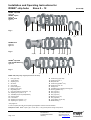
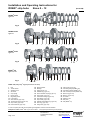
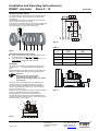
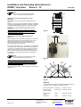
Installation and Operating Instructions for ROBA®- slip hubs Sizes 0 – 12 (B.1.0.GB) Please read and observe this Operating Instruction carefully! A possible malfunction or failure of the clutch and damage may be caused by not observing it. Table of contents: Page 1: - Table of contents - Manufacturer’s declaration - Safety regulations - Safety and information signs Page 5: - Rustproof friction pairing - Assembly instructions - Assembly Page 6: - Bearing bushing - Needle bearing - Cup spring layer Page 2: - Clutch views - Parts list Page 3: - Clutch views - Parts list Page 7: - Torque adjustment Page 8: - Torque adjustment - Disposal Page 4: - Function - Supply condition - Friction lining Manufacturer’s declaration The product is a component within the scope of the Machinery Directive 98/37/EC for installation into machines or equipment. An initial start-up is prohibited until it has been noticed that the machinery or the equipment into which this product has been incorporated correspond to the EC-Directive. Safety regulations The submitted installation and operating instructions (E+B) are part of the shipment. Keep the E+B always well accessible near the ROBA®-slip hub. Danger! 12 If the ROBA -slip hub has been modified or retrofitted. 12 If the relevant standards of the safety or installation conditions are not observed. ® Necessary protective measures to be undertaken by the user 12 Cover all moving parts for protection against squeezing, seizing, dust deposit and hit of foreign objects. 12 Do not breathe in the friction lining deposits. Suck off the dust in case of cleaning. 12 The ROBA -slip hub heats-up when slipping. => Caution very hot – do not touch. ® Only qualified and well-trained specialists should work on the units to avoid any personal injury or damage to machinery under observance of the valid standards and guidelines. The installation and operating instructions are to be read carefully before installation and operation. With these safety notes no claim on completeness is raised! Attention: Based on the guideline 94/9/EC (ATEX-guideline) this product is not suitable for the application in potential explosive areas without evaluation of the conformity. Safety and information signs Attention! Danger of injury for persons and damage at the machine possible. Note! Reference to important points which are to be considered. 21/02/2005 K/KR Page 1 of 8 Chr. Mayr GmbH + Co. KG Eichenstraße 1 D-87665 Mauerstetten Germany Tel.: 08341 / 804-241 Fax: 08341 / 804-422 http://www.mayr.de eMail: [email protected] Installation and Operating Instructions for ROBA®- slip hubs Sizes 0 – 12 (B.1.0.GB) ® ROBA -slip hub Type 100 ® ROBA -sproc Type 110 ® ROBA -max Type 170 Fig. 1 8 1(26) *7(*27) 6 12 6 2 5 5 13 3 4 14 9 ® ROBA -min Type 121 Type 123 Fig. 2 24(25) *23 19 6 2 5 5 13 4 ® ROBA -slip hub with needle bearing Type 160 Fig. 3 28 *30 16 16 29 5 5 13 4 Parts List (Only mayr®-original parts are to be used) 1 2 3 4 5 6 7* 8 9 10 11 12 13 14 15 Hub (Type 100) Thrust washer Adjusting nut 0 Set screw Cup springs Friction lining No. 1 Bushing (Type 100) Regulating screw Cup spring support pins (sizes 6 - 12) Adjusting nut .2 (sizes 3 – 5) Threaded pin (for torque adjustment) Chain sprocket Lock washer Adjusting nut 0 (sizes 6 – 12) Adjusting nut 1 (sizes 0 – 5) 16 17* 18* 19 20* 21 22 23* 24 25 26 27* 28 29 30* Friction lining (Type 160) Friction lining No. 2 Rustproof disc Friction lining (ROBA®-min) Friction lining No. 4/5 Hexagon nut Threaded pin for moulding securing part Bushing (ROBA®-min) Hub (Type 121) Hub (Type 123) Hub (Type 170) Bushing (Type 170) Hub (Type 160) Thrust washer (Type 160) Needle bearing * See pages 4/5 In case of a spare part order the complete Type designation and size must be indicated. Example for order: ROBA®-sproc Type 110.210, size 1, 1 set (2 pieces) friction linings component 6. 21/02/2005 K/KR Page 2 of 8 Chr. Mayr GmbH + Co. KG Eichenstraße 1 D-87665 Mauerstetten Germany Tel.: 08341 / 804-241 Fax: 08341 / 804-422 http://www.mayr.de eMail: [email protected] 15 11 21 (10) 22 Installation and Operating Instructions for ROBA®- slip hubs Sizes 0 – 12 (B.1.0.GB) ® ROBA -lastic Type 135 Fig. 4 35 34 8 1 36 6 31 33 32 6 2 37 6 2 5 13 3 4 ® ROBA -lastic Type 131 Fig. 5 38 40 39 8 1 44 42 36 6 5 5 4 ® ROBA -lastic Type 132 Fig. 6 45 46 43 1 36 6 41 6 13 3 4 9 ® ROBA -LD Type 133, 134 Fig. 7 56 53 54 49 50 8 1 36 6 48 6 2 5 55 51/52 Parts List (Only mayr®-original parts are to be used) 1 2 3 4 5 6 8 13 31 32 33 34 Hub Thrust washer Adjusting nut 0 Set screw Cup springs Friction lining Regulating screw Lock washer Claw element (Type 135) Transmission flange (Type 135) Cap screws (Type 135) Pocket element (Type 135) 35 36 37 38 39 40 41 42 43 44 45 46 Damping buffer Bushing Flange (Type 131) Flexible ring (Type 131) Hub for flexible coupling (Type 131) Cap screws (Type 131) Transmission flange (Type 132) Claw flange (Type 132) Cap screws (Type 132) Flexible intermediate ring (Type 132) Claw ring (Type 132) Flange hub (Type 132) 47 48 49 50 51 52 53 54 55 56 Cap screws (Type 132) Connecting flange (ROBA®-LD) Connecting washer (ROBA®-LD) Hex. head cap screws (ROBA®-LD) Sleeve 0 (Type 133) Sleeve 1 (Type 134) Fit screws Hexagon nuts Disc pack Hub (ROBA®-D) In case of a spare part order the complete Type designation and size must be indicated. Example for order: ROBA®-lastic Type 135.210 Size 1, 1 set (2 pieces) friction linings component 6 21/02/2005 K/KR Page 3 of 8 Chr. Mayr GmbH + Co. KG Eichenstraße 1 D-87665 Mauerstetten Germany Tel.: 08341 / 804-241 Fax: 08341 / 804-422 http://www.mayr.de eMail: [email protected] Installation and Operating Instructions for ROBA®- slip hubs Sizes 0 – 12 (B.1.0.GB) Function (Fig. 1) Supply condition ROBA®-slip hubs are used as overload protection for machine drives with chain sprockets or belt pulleys. The drive element (chain sprocket or similar) is placed on the bushing (7) and clamped between the friction linings (6) with the aid of the thrust washer (2), the cup springs (5) and the adjusting nut (3) with the lock washer (13). The more powerfully the cup springs (5) are compressed by the adjusting nut (3), the higher the torque at which the drive element slips. The precise torque setting operation is described on page 7/8. ROBA-slip hubs are supplied in a pre-assembled condition. The cup spring layer or friction lining assembling depends on the used type and corresponds to the order indication provided by the customer. ROBA®-slip hubs are available with finish bore (bore fit H7) and keyway to DIN 6885 (fit of keyway JS9) as standard. We recommend to use a k6-fit for the shaft. For other tolerances please contact the factory. If the order does not contain any details regarding the overall width of the drive element (chain sprocket etc.), we supply the bearing bushing (7) for the maximum overall width. The ROBA-slip hub is thermally stressed as a function of the slip speed, slip time and the adjusted torque. The described friction power parameters must not be exceeded, so that the friction linings of the ROBA-slip hub are not overheated or damaged. The values represented in the diagram of recommended values are reference values and represent max. slip speed limits. The speed limits refer to a max. slip time of 1 sec. The slip speed must be reduced with a correspondingly longer slip time. In the case of doubt application-related friction work calculations are to be carried out. When exceeding the permissible slip duration the ROBA-slip hub is overloaded => damage of the friction linings. Friction linings As shown in below-mentioned Table 1 four different types of friction linings are available. The torque and speed details given in the slip hub catalogue apply to standard friction linings for dry running. For the other friction linings the corresponding values are shown in Table 1 or must be requested for the respective application. Table 1 Friction lining Application Attainable torques of M max. 1 Standard for dry running 100 % 2 Rustproof friction paring 100 % 4 Bronze friction lining for oil bath 30 % 5 Special low-friction material (only for single cup spring layer and with reduced friction power) 50 % For monitoring the slip speed use the speed monitor ROBA®-tron. Table 2 Limiting torque for overload [Nm] 21/02/2005 K/KR Page 4 of 8 Size Type 100.1 - - Type 100.2 - - Type 100.3 - - 0 2 - 10 10 - 20 18 - 30 01 6 - 30 30 - 60 60 - 90 1 14 - 70 70 - 130 130 - 200 2 26 - 130 130 - 250 250 - 400 3 50 - 250 250 - 550 550 - 800 4 110 - 550 550 - 1100 1100 - 1600 5 140 - 700 700 - 1400 1400 - 2100 6 240 - 1200 1200 - 2400 - 7 400 - 2000 2000 - 4000 - 8 680 - 3400 3400 - 6800 - 9 1200 - 6000 6000 - 12000 - 10 2000 - 10000 10000 - 20000 - 11 3400 - 17000 17000 - 34000 - 12 5000 - 25000 25000 - 50000 - Chr. Mayr GmbH + Co. KG Eichenstraße 1 D-87665 Mauerstetten Germany Tel.: 08341 / 804-241 Fax: 08341 / 804-422 http://www.mayr.de eMail: [email protected] Installation and Operating Instructions for ROBA®- slip hubs Sizes 0 – 12 (B.1.0.GB) Rustproof friction pairing Y A 0,8 b H8 Ød Ød0 1,6 ground A Ødk 0,8 ground The standard friction lining can form a rust compound with cast iron and iron surfaces, which increases the slip torque quite considerably. Therefore ROBA®-slip hubs can be equipped with a rustproof pairing of friction linings (friction lining 2). This rustproof friction lining pairing consists of two stainless steel discs (item 18), anchored in the slip hub, and of two special friction linings (item 17) which cannot stick (Fig. 8). X A Fig. 10 Table 3 1 Fig. 8 7 18 17 17 18 2 Important assembly instructions 12 Bores, shafts, friction linings and friction surfaces at the drive element must be free of oil and grease. 12 The shaft surface is finely turned or ground (Ra= 0,8 µm) Shaft material: yield point at least 350 N/mm2. Size X [mm] Y [mm] 0-2 0,05 0,10 3-5 0,08 0,15 6-8 0,10 0,20 9 - 12 0,12 0,30 Assembly The series of the assembly is to be taken from the explosion drawings Figs. 1 – 4 or with the needle bearing design from Fig. 9. Before assembling the adjusting nut (item 3), the thread of the adjusting nut and the lock washer must be slightly greased. Important! Observe the correct cup spring layer (see paragraph cup spring layer)! It must be ensured that no grease gets onto the friction linings! 16 12 Ød H7 k6 During assembly of the ROBA®-lastic types additionally the operation instruction of the flexible coupling is to be taken. The slip hub can be fixed axially onto the motor shaft end by means of a regulating screw (item 8, Fig. 1) or as shown on Fig. 11 by means of a cover. ROBA®-slip hubs are available with finish bore (bore fit H7) and keyway to DIN 6885 (fit of keyway JS9) as standard. We recommend to use a k6-fit for the shaft (see Fig. 11). The drive element should show exact plane parallelism and a surface ground finely in the bore range or in the range of friction surfaces (see Fig. 10 and Table 3). A Fig. 11 31 32 30 Fig. 9 21/02/2005 K/KR Page 5 of 8 Chr. Mayr GmbH + Co. KG Eichenstraße 1 D-87665 Mauerstetten Germany Tel.: 08341 / 804-241 Fax: 08341 / 804-422 http://www.mayr.de eMail: [email protected] Installation and Operating Instructions for ROBA®- slip hubs Sizes 0 – 12 (B.1.0.GB) Bearing bushing (items 7, 23, 27) If the order contains no details regarding the overall width of the drive element (chain sprocket, etc.) we supply the bearing bushing for the maximum overall width (bmax). If an overall width narrower than bmax is needed, the bearing bushing must be shortened accordingly at the end without the internal chamfer. The bearing bushing is to be assembled with the internal chamfer at the front, as shown in Fig. 12. Fig. 13 Sizes 0 – 5 Single layer bearing bushing internal chamfer Fig. 12 Bearing bushing width standard friction pairing = : overall width + 1,5 x friction lining width + 0,5 mm Fig. 14 Sizes 0 – 5 Double layer Bearing bushing width rustproof friction pairing = : overall width + 1,5 x friction lining width + 2 x width rustproof disc Where there are high radial loads and large slipping frequencies, we recommend to use the slip hub with needle bearing. Needle bearing (item 30) As the needle bearing (item 30) cannot be adjusted to the overall width "b" with its length, the overall width “b” is commanded with the Type 160 (refer to Table 4). The drive element is to be drilled with the drilling tolerance N7 and it has to be pressed onto the needle bearing as shown in Fig. 9. Fig. 15 Sizes 1 – 2 Triple layer Table 4 Size Friction lining width "s" [mm] Width of the drive element "b" Type 160 [mm] 1 3 7 2 3 10,3 3 4 12,5 4 4 16 5 5 18 Sizes 3 – 5 Triple layer Fig. 16 Fig. 17 Cup spring layers 14 A correct cup spring layer is the condition for a satisfactory function of the clutch and for a torque adjustment without problems. The respective type dependent cup spring layers are shown in the subsequent Figs. 13 to 19. 9 14 9 Rule of thumb: ROBA-slip hub Type 1_0.1_ _ for large friction work and low torque (cup springs single layer, single applied force); Sizes 6 - 12 ROBA-slip hub Type 1_0.2_ _ for medium friction work and higher torque (cup springs double layer, double applied force); ROBA- slip hub Type 1_0.3_ _ for small friction work and high torque (cup springs triple layer, triple applied force). 21/02/2005 K/KR Page 6 of 8 Fig. 18 Fig. 19 Single layer Double layer Chr. Mayr GmbH + Co. KG Eichenstraße 1 D-87665 Mauerstetten Germany Tel.: 08341 / 804-241 Fax: 08341 / 804-422 http://www.mayr.de eMail: [email protected] Installation and Operating Instructions for ROBA®- slip hubs Sizes 0 – 12 (B.1.0.GB) Torque adjustment Sizes 0 - 5 Both ambient conditions and longer downtimes can impair the set slipping torque. Torque adjustment with cup springs triple layer sizes 1-5 (Figs. 15 and 16). Load-specifically larger deviations of the slipping torque can occur with triple layers. The values mentioned on the setting chart are only recommended values. The ROBA®-slip hubs with cup springs triple layer do not have a setting chart which is glued on. Adjustment sizes 1 and 2 Type 1_ _.310 adjusting nut "0". The thrust washer (item 2) has twelve markings on the back, the adjusting nut (item 3) has four markings on the back (Fig. 20). The adjusting nut with the lock washer are moved manually until they make contact with the cup springs; the four markings must coincide with the markings of the thrust washer. The adjusting nut is now turned by the number of graduations (using a face wrench), corresponding to the required slipping torque. A setting chart is attached to the clutch and can be used to obtain the number of graduations to be set to suit the torque. When the torque is set the first time the ROBA®-slip hub should slip several times at 50 % of the maximum torque in order to obtain an uniform friction surface of the friction lining. An occasional adjustment is necessary depending on the slipping frequency due to lining wear. Note: Due to cup spring tolerances torque setting values might be only recommended values. Torque adjustment with standard adjusting nut (item 3) Cup springs single or double layers. The thrust washer (item 2) has twelve markings on the back (size 0; 24 markings), the adjusting nut (item 3) has four markings (Fig. 20). The adjusting nut with the lock washer are moved manually until they make contact with the cup springs; the four markings must coincide with markings of the thrust washer. The adjusting nut is now turned by the number of graduations, corresponding to the required slipping torque. A setting chart (Fig. 21) is glued onto the clutch sizes 1 – 5, and can be used to obtain the number of graduations to be set to suit the torque. After the torque has been set, the adjusting nut must be secured by tightening the set screw (item 4). Adjustment sizes 1 and 2 Type 1_ _.311 adjusting nut "1" (for radial adjustment with a hook wrench). Distance "a" in Fig. 23 indicates the size of the set slipping torque setting regardless of the degree of the friction lining wear. An adjusting diagram is attached to the clutch, which shows the dimension “a” for a given slipping torque related to the cup spring layer. After the torque has been set, the adjusting nut has to be secured via a set screw which is to be screwed in radially into one groove of the hub. A clamping onto the thread is not permissible, as shown in Fig. 24. For size 0 the setting chart is in the operation manual (Fig. 21). corresponds to one graduation One rotation corresponds to 12 graduations or 24 graduations with size 0 respectively. Adjustment sizes 3 - 5 Type 1_ _.311 adjusting nut "1" (for radial adjustment with a hook wrench). Tighten the adjusting nut without any force until it makes contact with the cup springs. The adjusting has to be secured via a set screw which is to be screwed in radially into one groove of the hub. A clamping onto the thread is not permissible, as shown in Fig. 24. Now uniformly tighten the single set screws (item 11) in the adjusting nut in stages of approx. ¼ turn until the dimension "a" from the adjusting diagram or the required torque is achieved. Lock the set screws with hexagon nuts (item 21). 2 Thread for drawing-off the slip hub from the shaft 3 The suitable wrenches for the torque adjustment with slip hubs are available ex works. 4 Fig. 20 _______________________ Surface ground chain sprocket for friction lining No. 1, run-in condition 2 TS ROBA®- slip hub size 0 Turn nut to contact cup spring, then count TS. 24TS=1 turn Example: In case of a slip hub, size 0, with single layer cup springs a torque of 5 Nm shall be set. Using the chart you can see immediately that 8 graduations are necessary for this case (Fig. 21). After the torque has been set, the adjusting nut must be secured by tightening the set screw (item 4). Single cup spring / \ Nm 2 4 5 6 8 10 TS 4 6 8 10 13 16 Double cup spring // Nm 9 12 15 17 20 TS 4 5 6 7 8 Triple cup spring /// Nm 18 23 26 30 TS 5 6 7 8 Fig. 21 21/02/2005 K/KR Page 7 of 8 Chr. Mayr GmbH + Co. KG Eichenstraße 1 D-87665 Mauerstetten Germany Tel.: 08341 / 804-241 Fax: 08341 / 804-422 http://www.mayr.de eMail: [email protected] Installation and Operating Instructions for ROBA®- slip hubs Sizes 0 – 12 (B.1.0.GB) a Note: Due to cup spring tolerances torque setting values can only be recommended values. 14 9 Adjusting the torque with adjusting nut for radial adjustment These ROBA®-slip hubs do not have a setting chart which is glued on. Distance "a" in Figs. 22 and 23 indicates the sizes of the slipping torque setting regardless of the degree of the friction lining wear. An adjusting table is attached to the clutch, which shows the dimension “a” for a given slipping torque related to the cup spring layer. After the torque has been set, the adjusting nut has to be secured via a set screw which is to be screwed in radially into one groove of the hub. A clamping onto the thread is not permissible, as shown in Fig. 24. Fig. 22 flush a Adjusting the torque with standard adjusting nut sizes 6 – 12 When the torque is set the first time the ROBA®-slip hub should slip several times at 50 % of the maximum torque in order to obtain an uniform friction surface of the friction lining. An occasional adjustment is necessary depending on the slipping frequency due to lining wear. In the case of slip hubs sizes 6 – 12, dimension "a" is determined by using the chart, which is glued, and moved on the adjusting nut (item 14) in accordance with the Fig. 22 with a face wrench via the hexagon-socket of the cup spring supporting pins (9) without any force until they make contact with the cup springs, or if necessary the cup spring supporting pins must slightly be turned back Note: Do not unscrew the cup spring supporting pins above the resistance of the snap ring. Fig. 23 After the torque has been set, the adjusting nut has to be secured via a set screw (23) which is to be screwed in radially into one groove of the hub. A clamping onto the thread is not permissible, as shown in Fig. 24. Then the cup spring supporting pins (item 9) are tightened uniformly in stages of approx. ¼ turn until they are flush with the adjusting nut. 2 10 1 22 Fig. 24 Disposal The components of our slip hubs must separately be supplied to the disposal due to the different material components 21/02/2005 K/KR Page 8 of 8 All metal components: steel scrap (Code No. 160117) Friction linings: (press materials) brake linings (Code No. 160112) Friction linings: (plastic) plastic (Code No. 160119) Elastomers: plastic (Code No. 160119) Chr. Mayr GmbH + Co. KG Eichenstraße 1 D-87665 Mauerstetten Germany Tel.: 08341 / 804-241 Fax: 08341 / 804-422 http://www.mayr.de eMail: [email protected]