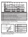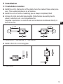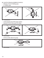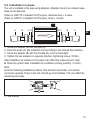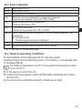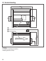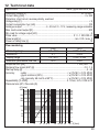
1
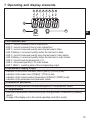
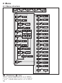
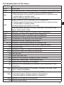
Operating instructions
Ultrasonic flow rate sensor
UK
704328 / 01 06 / 2010
SU7000
Contents
1 Preliminary note���������������������������������������������������������������������������������������������������4
1.1 Symbols used������������������������������������������������������������������������������������������������4
2 Safety instructions�����������������������������������������������������������������������������������������������4
3 Functions and features����������������������������������������������������������������������������������������5
4 Function���������������������������������������������������������������������������������������������������������������5
4.1 Processing of the measured signals��������������������������������������������������������������5
4.2 Volumetric flow monitoring�����������������������������������������������������������������������������5
4.3 Consumed quantity monitoring����������������������������������������������������������������������6
4.3.1 Consumed quantity monitoring with pulse output���������������������������������6
4.3.2 Consumed quantity monitoring with preset meter��������������������������������6
4.4 Monitoring of temperatures����������������������������������������������������������������������������6
4.5 Volumetric flow or temperature monitoring / switching function���������������������7
4.6 Volumetric flow or temperature monitoring / analogue function ��������������������7
4.7 Start-up delay [dSt]����������������������������������������������������������������������������������������9
4.8 Customer-specific calibration (CGA)�����������������������������������������������������������10
5 Installation��������������������������������������������������������������������������������������������������������� 11
5.1 Installation location�������������������������������������������������������������������������������������� 11
5.2 Installation in pipes��������������������������������������������������������������������������������������13
5.3 Protection against high medium temperatures��������������������������������������������14
6 Electrical connection������������������������������������������������������������������������������������������14
7 Operating and display elements������������������������������������������������������������������������15
8 Menu������������������������������������������������������������������������������������������������������������������16
8.1 Menu structure���������������������������������������������������������������������������������������������16
8.2 Explanation of the menu������������������������������������������������������������������������������17
9 Parameter setting����������������������������������������������������������������������������������������������18
9.1 General parameter setting���������������������������������������������������������������������������18
9.2 Settings for volumetric flow monitoring��������������������������������������������������������20
9.2.1 Settings for limit value monitoring with OUT1�������������������������������������20
9.2.2 Settings for limit value monitoring with OUT2�������������������������������������20
9.2.3 Scaling of the analogue value for volumetric flow������������������������������20
9.3 Settings for monitoring of consumed quantities�������������������������������������������20
9.3.1 Settings for quantity monitoring by pulse output���������������������������������20
2
9.3.2 Settings for quantity monitoring using the preset meter ��������������������21
9.3.3 Settings for meter reset controlled by the program����������������������������21
9.3.4 Switch off the meter reset�������������������������������������������������������������������21
9.3.5 Settings for meter reset by an external signal �����������������������������������21
9.4 Settings for temperature monitoring������������������������������������������������������������21
9.4.1 Settings for limit value monitoring with OUT2�������������������������������������21
9.4.2 Scaling of the analogue value for temperature�����������������������������������22
9.5 User settings (optional)��������������������������������������������������������������������������������22
9.5.1 Determine the standard unit of measurement for volumetric flow������22
9.5.2 Configuration of the standard display�������������������������������������������������22 UK
9.5.3 Setting the output logic�����������������������������������������������������������������������22
9.5.4 Customer-specific calibration of the curve of measured values���������22
9.5.5 Calibration reset���������������������������������������������������������������������������������23
9.5.6 Setting the start-up delay��������������������������������������������������������������������23
9.5.7 Setting the damping of the measured values�������������������������������������23
9.5.8 Setting the error behaviour of OUT1 / OUT2��������������������������������������23
9.5.9 Selection of the medium to be monitored�������������������������������������������23
9.6 Service functions�����������������������������������������������������������������������������������������23
9.6.1 Reading the min./max. values for volumetric flow������������������������������23
9.6.2 Reset all parameters to the factory setting�����������������������������������������24
9.7 Setting of the preset meter / pulse value (ImPS)�����������������������������������������24
10 Operation���������������������������������������������������������������������������������������������������������26
10.1 Read the set parameters���������������������������������������������������������������������������26
10.2 Changing the display unit in the Run mode�����������������������������������������������26
10.3 Error indication������������������������������������������������������������������������������������������27
10.4 General operating conditions���������������������������������������������������������������������27
11 Scale drawing��������������������������������������������������������������������������������������������������28
12 Technical data��������������������������������������������������������������������������������������������������29
12.1 Setting ranges ������������������������������������������������������������������������������������������30
13 Factory setting�������������������������������������������������������������������������������������������������31
3
1 Preliminary note
1.1 Symbols used
►
>
[…]
→
Instruction
Reaction, result
Designation of buttons, switches or indications
Cross-reference
Important note
Non-compliance can result in malfunctions or interference.
2 Safety instructions
• Please read this document prior to installing the unit. Ensure that the product is
suitable for your application without any restrictions.
• Improper or non-intended use may lead to malfunctions of the unit or to unwanted effects in your application.
• That is why installation, electrical connection, set-up, operation and maintenance of the unit must be carried out by qualified personnel authorised by the
plant operator.
• In all applications test the compatibility of the product materials (→ 12 Technical data) with the media to be measured.
For the scope of validity cULus:
The device shall be supplied from an isolating transformer having a secondary
Listed fuse rated as noted in the following table.
Overcurrent protection
Control-circuit wire size
AWG
(mm2)
26
(0.13)
24
(0.20)
22
(0.32)
20
(0.52)
18
(0.82)
16
(1.
4
Maximum protective device rating
Ampere
1
2
3
5
7
10
3 Functions and features
The unit monitors liquids.
It detects the 3 process categories volumetric flow, consumed quantity, medium
temperature.
Applications:
• Water
• Glycol solutions
• Oils (viscosity: ≤ 68 mm²/s at 40°C)
Selection of the medium to be monitored → 9.5.9.
UK
4 Function
4.1 Processing of the measured signals
• The unit displays the current process values.
• It generates 2 output signals according to the parameter setting.
OUT1: 3 selection options........................................................... parameter setting
switching signal for volumetric flow limit values ....................................... (→ 9.2.1)
or pulse sequence for totalising meter ..................................................... (→ 9.3.1)
or switching signal for preset counter ....................................................... (→ 9.3.2)
OUT2: 4 selection options
switching signal for volumetric flow limit value ......................................... (→ 9.2.2)
or switching signal for temperature limit value ......................................... (→ 9.4.1)
or analogue signal for volumetric flow ...................................................... (→ 9.2.3)
or analogue signal for temperature .......................................................... (→ 9.4.2)
OUT2 (pin 2) cannot only be used as an output
but also as an input for an external reset signal: ...................................... (→ 9.3.5)
4.2 Volumetric flow monitoring
The flow rate is monitored by an ultrasonic meter, the measured signals by the
electronics.
• 2 switching signals for volumetric flow limit values can be provided (output 1
and output 2). For the switching functions → 4.5.
• An analogue signal proportional to the volumetric flow (4...20 mA or 0...10 V)
can be provided on output 2. For the analogue functions → 4.6.
5
4.3 Consumed quantity monitoring
The unit has an internal quantity meter which continuously totals the volumetric
flow. The sum corresponds to the current consumed quantity since the last reset.
• The current meter count can be indicated.
• In addition the value before the last reset is stored. This value can also be
indicated.
The meter saves the totalled consumed quantity every 10 minutes. After a power failure
this value is available as the current meter count. If a time-controlled reset is set, the
elapsed time of the set reset interval is also stored. So the possible data loss can be
maximum 10 minutes.
The meter can be reset as follows:
• Manual reset (→ 9.3.3).
• Time-controlled automatic reset (→ 9.3.3).
• External input signal on pin 2 (→ 9.3.5)
4.3.1 Consumed quantity monitoring with pulse output
Output 1 provides a counting pulse if the value set in [ImPS] is reached (→ 9.3.1).
4.3.2 Consumed quantity monitoring with preset meter
2 types of monitoring are possible:
• Time-dependent quantity monitoring
-- Settings: [ImPS] = quantity x, [ImPR] = [no], [rTO] = time t.
-- If the quantity x is reached during the time t, output 1 switches and remains
switched until the meter is reset.
-- If the quantity x has not been reached after the time t, the meter is automatically reset and counting starts again; output 1 does not switch.
• Quantity monitoring not time-dependent
-- Settings: [ImPS] = quantity x, [ImPR] = [no], [rTO] = [OFF].
-- If the quantity x is reached, output 1 switches and remains switched until the
meter is reset.
4.4 Monitoring of temperatures
• A switching signal for temperature limit values can be provided on output 2. For
the switching functions → 4.5.
• An analogue signal proportional to the temperature (4...20 mA or 0...10 V) can
be provided on output 2. For the analogue functions → 4.6.
6
4.5 Volumetric flow or temperature monitoring / switching
function
OUTx changes its switching state if it is above or below the set switching limits
(SPx, rPx). The following switching functions can be selected:
• Hysteresis function / normally open (fig. 1): [OUx] = [Hno].
• Hysteresis function / normally closed (fig. 1): [OUx] = [Hnc].
First the set point (SPx) is set, then the reset point (rPx) at the requested
distance.
• Window function / normally open (fig. 2): [OUx] = [Fno].
UK
• Window function / normally closed (fig. 2): [OUx] = [Fnc].
The width of the window can be set by means of the distance between SPx and
rPx. SPx = maximum value, rPx = minimum value.
�
��
��
1
��
�
��
��
2
��
��
�
�
�
���
�
�
�
�
���
�
�
�
���
���
HY = hysteresis; FE = window; examples for volumetric flow monitoring
When set to the window function the set and reset points have a fixed hysteresis of 0.25 %
of the final value of the measuring range. This keeps the switching state of the output stable
if the volumetric flow varies slightly.
4.6 Volumetric flow or temperature monitoring / analogue
function
• The analogue start point [ASP] determines at which measured value the output
signal is 4 mA or 0 V.
• The analogue end point [AEP] determines at which measured value the output
signal is 20 mA or 10 V.
Minimum distance between [ASP] and [AEP] = 20 % of the final value of the
measuring range.
7
Voltage output 0 ... 10 V (example volumetric flow monitoring)
Factory setting
Measuring range scaled
�����
�����
��
��
�
�
���
�
�
� ���
��� ���
�
MEW = final value of the measuring range
In the set measuring range the output signal is between 0 and 10 V.
It is also indicated:
Volumetric flow above the measuring range: output signal > 10 V.
Current output 4 ... 20 mA (example volumetric flow monitoring)
Factory setting
Measuring range scaled
������
������
��
��
�
�
�
���
�
� ���
MEW = final value of the measuring range
In the set measuring range the output signal is between 4 and 20 mA.
It is also indicated:
Volumetric flow above the measuring range: output signal > 20 mA.
8
��� ���
�
4.7 Start-up delay [dSt]
If the start-up delay is active ([dSt] > [0]), note: as soon as the volumetric flow
quantity exceeds 0.5 % of the final value of the measuring range (VMR), the following processes are carried out:
• The start-up delay is activated.
• Output 1 switches as programmed: ON for NO function, OFF for NC function.
• Output 2 switches when the flow is evaluated ([SEL2] = [FLOW]) as programmed: ON for NO function, OFF for NC function).
[dSt] only has an effect on the switching signals for volumetric flow monitoring.
UK
After the activation of the start-up delay there are 3 options:
• The volumetric flow quantity increases quickly and reaches the switch point /
good range within dSt → outputs remain active.
• The volumetric flow quantity increases slowly and does not reach the switch
point / good range within dSt → outputs are reset.
• The volumetric flow quantity falls below 0.5 % within dSt → outputs are immediately reset; dSt is stopped.
Example: dSt for hysteresis function
� �
�
�
�
�
�
�
��
��
����
�
�
�
�
1
2
3
4
5
6
7
���
���
�
���
���
Volumetric flow quantity Q reaches 0.5% of VMR → dSt starts, output becomes active.
dSt elapsed, Q reached SP → output remains active.
Q below SP, but above rP → output remains active.
Q below rP → output is reset.
Q reaches again 0.5 % of VMR → dSt starts, output becomes active.
dSt elapsed, Q has not reached SP → output is reset.
Q reaches SP → output becomes active.
9
Example: dSt for window function
�
�
�
�
�
�
�
�
�
��
��
����
�
�
�
�
1
2
3
4
5
6
7
8
���
���
�
���
���
Volumetric flow quantity Q reaches 0.5% of VMR → dSt starts, output becomes active.
dSt elapsed, Q reached good range → output remains active.
Q above SP (leaves good range) → output is reset.
Q again below SP → output becomes active again.
Q below rP (leaves good range) → output is reset again.
Q reaches again 0.5 % of VMR → dSt starts, output becomes active.
dSt elapsed, Q has not reached good range → output is reset.
Q reaches good range → output becomes active.
4.8 Customer-specific calibration (CGA)
This calibration changes the slope of the curve of measured values. It influences
the display and the outputs.
�
��������
��������
�������
A
��
��
��
���
�
operating value for display and
output signals
volumetric flow
Q
MEW final value of the measuring
range
V0
curve of measured values
without calibration
V1,
curve of measured values
V2
after calibration
The change in the increase is indicated in percent. 100% corresponds to the factory calibration. It can be reset(→ 9.5.5).
10
5 Installation
5.1 Installation location
►► Install the unit in that section of the plant where the medium flows under pressure. This avoids disturbance by air bubbles.
►► Install the unit so that the measuring pipe is always completely filled.
►► Arrange for inlet and outlet pipe lengths. Disturbances caused by bends,
valves, reductions, etc. are compensated for.
It applies in particular: no shut-off and control devices are allowed directly in
front of the unit
UK
�����
�����
�
�
�
�
S = disturbance; D = pipe diameter; F = flow direction
►► Install in front of or in a rising pipe.
�
�
F = flow direction
11
►► Avoid the following installation locations:
• Directly in front of a falling pipe.
• In a falling pipe.
�
�
FF = flow direction
• At the highest point of the pipe system.
• Directly in front of the spout of a pipe.
�
�
F = flow direction
• On the suction side of a pump.
�
F = flow direction
12
5.2 Installation in pipes
The unit is installed in the pipe using adapters. Adapters have to be ordered separately as accessories.
Order no. E40178: 2 adapters for R¾ pipes, stainless steel + 2 seals.
Order no. E40151: 2 adapters for R¾ pipes, brass + 2 seals.
�
�
��
��
�
�
UK
��������������
1. Screw the adapter (B) into the pipe (A).
2. Place the seals (C) and install the unit according to the marked flow direction.
3. Screw the adapter (B) with the threads (D) until it is hand-tight.
4. Tighten the two adapters in opposite direction (tightening torque: 30 Nm).
After installation air bubbles in the system can affect the measurement. Help:
►► Rinse the system after installation for ventilation (rinsing quantity > 3 l/min.).
Note:
Avoid the following installation position: flow direction horizontal, unit vertical,
connector upwards. There is the risk of build-up of air bubbles. This can affect the
measuring accuracy.
�
F = flow direction
13
5.3 Protection against high medium temperatures
For medium temperatures over 50 °C some parts of the housing can heat up to
over 65 °C.
►► Protect the housing against contact with flammable substances and unintentional contact.
6 Electrical connection
The unit must be connected by a qualified electrician.
The national and international regulations for the installation of electrical
equipment must be adhered to.
Voltage supply to EN50178, SELV, PELV.
►► Disconnect power.
►► Connect the unit as follows:
����
�
�
�
�
Pin1
Pin3
Pin4
(OUT1)
Pin2
(OUT2/InD)
����
����
����
��������
����
�
Ub+
UbSwitching signal: limit values for volumetric flow.
Switching signal: quantity meter reached preset value.
Pulses: 1 pulse every time the defined volumetric flow quantity is reached.
Switching signal: limit values for volumetric flow.
Switching signal: limit values for temperature.
Analogue signal for volumetric flow.
Analogue signal for temperature.
Input for signal “meter reset”.
Core colours of ifm sockets:
1 = BN (brown), 2 = WH (white), 3 = BU (blue), 4 = BK (black).
14
��
7 Operating and display elements
���
���
���
��
��
�
����
�����
� � � � � � � �
�
��
��
����
������
UK
���
1 to 8: Indicator LEDs
- LED 1 = current volumetric flow in litres/minute.
- LED 2 = current volumetric flow in cubic metres/hour.
- LED 3 = current consumed quantity since the last reset in litres.
- LED 3 flashing = consumed quantity before the last reset in litres.
- LED 4 = current consumed quantity since the last reset in cubic metres.
- LED 4 flashing = consumed quantity before the last reset in cubic metres.
- LED 5 = current medium temperature in °C.
- LED 6 = consumed quantity in 103 cubic metres.
- LED 7, LED 8 = switching state of the corresponding output.
9: Alphanumeric display, 4 digits
- indication of the current volumetric flow (if [SELd] = [FLOW] is set).
- indication of the meter count (if [SELd] = [TOTL] is set).
- indication of the current medium temperature (if [SELd] = [TEMP] is set).
- indication of the parameters and parameter values.
10: Mode/Enter pushbutton
- Selection of the parameters and acknowledgement of the parameter values.
11: Set pushbutton
- Setting of the parameter values (scrolling by holding pressed, incremental by pressing
briefly).
- Change of the display unit in the normal operating mode (Run mode).
15
8 Menu
8.1 Menu structure
�����
�
�
����
���
�
�
�
�
�
��� �
���
��
���
�
�
�
�
�
�
�
��
�
�
�
�
� �� �
���
�
�
�
�
�
�
�
�
�
�
�
�
�
�
�
�
�
�
�
�
�
�
�
�
�
�
�
�
�
�
�
�
�
�
�
�
�
�
�
�
�
�
�
�
�
�
�
�
�
�
�
�
�
�
�
�
�
�
�
�
�
�
�
�
�
�
�
� = [Mode/Enter] / � = [Set]
l or m3 = current meter count in l, m3 or 1000 m3
l* or m3* = stored meter count in l, m3 or 1000 m3
16
�
8.2 Explanation of the menu
SP1/rP1
ImPS
ImPR
OU1
OU2
SP2/rP2
ASP
AEP
DIn2
EF
HI / LO
CGA
CAr
FOU1
FOU2
dSt
P-n
dAP
rTo
diS
Uni
SELd
SEL2
MEDI
rES
Maximum / minimum value for volumetric flow.
Pulse value.
Pulse repetition active (= function pulse output) or not active (= function preset meter).
Output function for OUT1 (volumetric flow or consumed quantity):
- Switching signal for limit values: hysteresis function or window function,
normally open or normally closed.
- Pulse or switching signal for quantity meter.
Output function for OUT2 (volumetric flow or temperature):
- Switching signal for limit values: hysteresis function or window function,
UK
normally open or normally closed.
- Analogue signal: 4-20 mA [I] or 0-10 V [U].
As an alternative: configure OUT2 (pin 2) as input for the external reset
signal: setting: [OU2] = [InD].
Maximum / minimum value for volumetric flow or temperature.
Analogue start value for volumetric flow or temperature.
Analogue end value for volumetric flow or temperature.
Configuration of the input (pin 2) for meter reset.
Extended functions / opening of menu level 2.
Maximum / minimum value memory for volumetric flow.
Customer-specific calibration of the curve of measured values.
Calibration reset.
Behaviour of output 1 in case of an internal fault.
Behaviour of output 2 in case of an internal fault.
Start-up delay.
Output logic: pnp / npn.
Measured value damping / damping constant in seconds.
Meter reset: manual reset / time-controlled reset.
Update rate and orientation of the display.
Standard unit of measurement for volumetric flow: litres/minute or cubic
metres/hour.
Standard process category of the display: volumetric flow value / meter
count / medium temperature.
Standard process category for evaluation by OUT2:
- Limit value signal or analogue signal for volumetric flow.
- Limit value signal or analogue signal for temperature.
Selection of the medium to be monitored.
Restore factory setting.
17
9 Parameter setting
During parameter setting the unit remains in the operating mode. It continues its
monitoring function with the existing parameters until the parameter setting has
been completed.
9.1 General parameter setting
3 steps must be taken for each parameter set:
1
Parameter selection
►► Press [Mode/Enter] until the
requested parameter is displayed.
����
������
���
2
Setting of the parameter value
►► Press [Set] and keep it pressed.
>> Current setting value of the parameter flashes for 5 s.
>> After 5 s: The setting value is
changed: incremental by pressing briefly or scrolling by holding
pressed.
Numerical values are incremented continuously. If the value is to be reduced: let
the display move to the maximum setting value. Then the cycle starts again at the
minimum setting value.
3 Acknowledgement of the parameter
value
►► Press [Mode/Enter] briefly.
>> The parameter is displayed again.
The new setting value is stored.
Setting of other parameters
►► Start again with step 1.
Finishing the parameter setting
►► Press [Mode/Enter] several times until the current measured value is displayed or wait
for 15 s.
>> The unit returns to the operating mode.
����
������
����
������
18
���
���
• Change from menu level 1 to menu level 2
►► Press [Mode/Enter] until [EF] is
displayed.
����
������
►► Press [Set] briefly.
>> The first parameter of the sub-menu
is displayed (here: [HI]).
����
������
���
���
• Locking / unlocking
The unit can be locked electronically to prevent unintentional wrong settings.
►► Make sure that the unit is in the
normal operating mode.
►► Press [Mode/Enter] + [Set] for 10 s.
>> [Loc] is displayed.
����
������
UK
���
During operation: > [Loc] is briefly displayed if you try to change parameter values.
►► Press [Mode/Enter] + [Set] for 10 s.
>> [uLoc] is displayed.
����
������
���
When delivered: unlocked.
• Time out:
If during parameter setting no pushbutton is pressed for 15 s, the unit exits the parameter setting mode. The parameter value is not changed.
For medium temperatures over 50 °C some parts of the housing can heat
up to over 65 °C.
In this case do not press the pushbuttons manually; instead use an object.
19
9.2 Settings for volumetric flow monitoring
9.2.1 Settings for limit value monitoring with OUT1
►► Select [OU1] and set the switching function:
-- [Hno] = hysteresis function/normally open,
-- [Hnc] = hysteresis function/normally closed,
-- [Fno] = window function/normally open,
-- [Fnc] = window function/normally closed.
►► Select [SP1] and set the value at which the output switches.
►► Select [rP1] and set the value at which the output switches back.
9.2.2 Settings for limit value monitoring with OUT2
►► Select [SEL2] and set [FLOW].
►► Select [OU2] and set the switching function:
-- [Hno] = hysteresis function/normally open,
-- [Hnc] = hysteresis function/normally closed,
-- [Fno] = window function/normally open,
-- [Fnc] = window function/normally closed.
►► Select [SP2] and set the value at which the output switches.
►► Select [rP2] and set the value at which the output switches back.
9.2.3 Scaling of the analogue value for volumetric flow
►► Select [SEL2] and set [FLOW].
►► Select [OU2] and set the function:
-- [I] = current signal proportional to volumetric flow (4…20 mA);
-- [U] = voltage signal proportional to volumetric flow (0…10 V).
►► Select [ASP] and set the value at which the minimum output value is
provided.
►► Select [AEP] and set the value at which the maximum output value is
provided.
9.3 Settings for monitoring of consumed quantities
9.3.1 Settings for quantity monitoring by pulse output
►► [Select [OU1] and set [ImP].
►► Select [ImPS] and set the volumetric flow quantity at which 1 pulse is
provided (→ 9.7).
►► Select [ImPR] and set [YES]: pulse repetition is active. Output 1 provides
a counting pulse when the value set in [ImPS] is reached.
20
9.3.2 Settings for quantity monitoring using the preset meter
►► Select [OU1] and set [ImP].
►► Select [ImPS] and set the volumetric flow quantity at which output 1
switches (→ 9.7).
►► Select [ImPR] and set [no]: pulse repetition is not active. The output
switches ON if the value set in [ImPS] is reached. It remains switched
until the meter is reset.
9.3.3 Settings for meter reset controlled by the program
►► Select [rTO] and continue with a) or b).
a) Reset the meter manually: press [Set] until [rES.T] is displayed.
Press [Mode/Enter] briefly.
b) Enter the value for time-controlled reset: Press [Set] until the requested value is displayed (intervals from 1 hour to 8 weeks).
►► Press [Mode/Enter] briefly.
UK
9.3.4 Switch off the meter reset
►► Select [rTO] and set [OFF]. The meter is only reset after overflow
(= factory setting).
9.3.5 Settings for meter reset by an external signal
►► Select [OU2] and then [InD].
►► Select [Din2] and set the reset signal:
-- [HI] = reset for high signal,
-- [LOW] = reset for low signal,
-- [+EDG] = reset for rising edge,
-- [-EDG] = reset for falling edge.
9.4 Settings for temperature monitoring
9.4.1 Settings for limit value monitoring with OUT2
►► Select [SEL2] and set [TEMP].
►► Select [OU2] and set the switching function:
-- [Hno] = hysteresis function/normally open,
-- [Hnc] = hysteresis function/normally closed,
-- [Fno] = window function/normally open,
-- [Fnc] = window function/normally closed.
►► Select [SP2] and set the value at which the output switches.
►► Select [rP2] and set the value at which the output switches back.
21
9.4.2 Scaling of the analogue value for temperature
►► Select [SEL2] and set [TEMP].
►► Select [OU2 ] and set the function:
-- [I] = current signal proportional to temperature (4…20 mA);
-- [U] = voltage signal proportional to temperature (0…10 V).
►► Select [ASP] and set the value at which the minimum output value is
provided.
►► Select [AEP] and set the value at which the maximum output value is
provided.
9.5 User settings (optional)
9.5.1 Determine the standard unit of measurement for volumetric flow
►► Select [Uni] and set the unit of measurement: [Lmin] or [m3h].
The setting only has an effect on the volumetric flow value. The counter
values (consumed quantity) are automatically displayed in the unit of measurement providing the highest accuracy
9.5.2 Configuration of the standard display
►► Select [SELd] and determine the standard process category.
-- [FLOW] = display shows the current volumetric flow value in the standard unit of measurement.
-- [TOTL] = display indicates the current meter count in l, m3 or 1000 m3.
-- [TEMP] = display indicates the current medium temperature in °C.
►► Select [diS] and determine the update rate and orientation of the display:
-- [d1] = update of the measured values every 500 ms.
-- [d2] = update of the measured values every 1000 ms.
-- [d3] = update of the measured values every 2000 ms.
-- [rd1], [rd2], [rd3] = display as for d1, d2, d3; rotated by 180°.
-- [OFF] = the display is switched off in the operating mode.
9.5.3 Setting the output logic
►► Select [P-n] and set [PnP] or [nPn].
9.5.4 Customer-specific calibration of the curve of measured values
►► Select [CGA] and set the value between 60 % and 140 %
(100 % = factory preset).
22
9.5.5 Calibration reset
►► Select [CAr].
►► Press [Set] and keep it pressed until [----] is displayed.
►► Press [Mode/Enter] briefly.
>> Value is reset (CGA = 100).
9.5.6 Setting the start-up delay
►► Select [dSt] and set the numerical value in seconds.
9.5.7 Setting the damping of the measured values
UK
►► Select [dAP] and the damping constant in seconds (t value 63 %).
9.5.8 Setting the error behaviour of OUT1 / OUT2
►► Select [FOU1] and determine the value:
-- [On] = output 1 switches ON in case of an error.
-- [OFF] = output 1 switches OFF in case of an error.
►► Select [FOU2] and determine the value:
-- [On] = output 2 switches ON in case of an error, the analogue signal
goes to the upper end stop value.
-- [OFF] = output 2 switches OFF in case of an error, the analogue signal
goes to the lower end stop value.
9.5.9 Selection of the medium to be monitored
►► Select [MEDI] and determine the required medium:
-- [H2O] = Water.
-- [GLYC] = Glycol solutions.
-- [OIL] = Oils..
9.6 Service functions
9.6.1 Reading the min./max. values for volumetric flow
►► Select [HI] or [LO] and press [Set] briefly.
[HI] = maximum value, [LO] = minimum value.
Delete memory:
►► Select [HI] or [LO].
►► Press [Set] and keep it pressed until [----] is displayed.
►► Press [Mode/Enter] briefly.
It makes sense to delete the memories as soon as the unit works under
normal operating conditions for the first time.
23
9.6.2 Reset all parameters to the factory setting
►► Select [rES], then press [Set] and keep it pressed until [----] is dis-
played.
►► Press [Mode/Enter] briefly.
The factory setting is listed at the end of the instructions (→ 13 Factory
setting).
It makes sense to write your own settings in this table before executing the
function.
9.7 Setting of the preset meter / pulse value (ImPS)
7 setting ranges are available:
LED
Display
Value
Resolution
1
3
0 0 0. 1
...
9 9 9. 9
0.1...999.9 l
0.1 l
2
3
1 0 0 0
...
9 9 9 9
1000...9999 l
1l
3
4
1 0. 0 0
...
9 9. 9 9
10.00...99.99 m³
0.01 m³
4
4
1 0 0. 0
...
9 9 9. 9
100.0...999.9 m³
0.1 m³
5
4
1 0 0 0
...
9 9 9 9
1000...9999 m³
1 m³
6
4+6
1 0. 0 0
...
9 9. 9 9
10 000...99 999 m³
10 m³
7
4+6
1 0 0. 0
...
9 9 9. 9
100 000...999 999 m³
100 m³
4+6
1 0 0 0
1 000 000 m³
Setting operation:
►► Set [OU1] to [ImP] (→ 9.3.2).
►► Press [Mode/Enter] until [ImPS] is displayed.
►► Press [Set] and keep it pressed.
>> The current numerical value flashes for 5 s, then the first of the 4 digits becomes active (digit flashes, can be changed).
►► Set the requested value as indicated in the following table.
►► First select the requested setting range. Then set the figure from the left digit to the
right digit.
►► Press [Mode/Enter] briefly when all 4 digits are set.
As soon as the first digit flashes there are 3 options:
24
►► Press [Set] once.
The flashing digit is increased. 9 is followed by 0 - 1 - 2, etc.
8 1. 2
1 x [Set] pressed 9 1. 2
1 x [Set] pressed 0 1. 2
1 x [Set] pressed 1 1. 2
►► Press [Set] and
keep it pressed.
The flashing digit is increased, 9 is followed by 0 and the digit
following on the left becomes active.
8 1. 8 3
[Set] permanently pressed 8 1. 9 3 UK
[Set] kept pressed 8 1. 0 3
3
3
3
3
If digit 1 is increased this way, the display changes to the next
higher setting range (9 is followed by 10, the decimal point is
moved one place to the right or the LED display changes).
8 1. 2 3
[Set] permanently pressed 9 1. 2 3
[Set] kept pressed 1 0 1. 2
►► Wait 3 s (do not
press any button).
The digit following on the right flashes (= becomes active).
8 1
no pushbutton pressed; after 3 s 8 1
after 3 s 8 1
after 3 s 8 1
2.
2.
2.
2.
3
3
3
3
If the fourth digit flashes unchanged for 3 s, digit 1 becomes active again (if the value of digit 1 is > 0).
after 3 s 8 1 2. 3
If digit 1 has the value “0”, the display changes to the next lower
setting range (the decimal point is moved one place to the left or
the LED display changes).
0 1 2. 3
after 3 s 1 2. 3 0
Next: Change digit 4 or wait 3 s and set digit 1.
after 3 s 1 2. 3 0
Highlighted grey ( 1 ) = flashing digit.
Note: If [Set] is pressed continuously, the display moves through all setting ranges; after the
end value it jumps back to the start value. Release [Set] briefly and start the setting again.
25
10 Operation
After power on and expiry of the power-on delay time (approx. 10 s) the unit is in
the Run mode (= normal operating mode). It carries out its measurement and evaluation functions and generates output signals according to the set parameters.
• Operation indication → chapter 7 Controls and indicating elements.
• During the power-on delay time the outputs are switched as programmed: ON
for NO function (Hno / Fno) and OFF for NC function (Hnc / Fnc).
• If output 2 is configured as analogue output, the output signal is at the final
value of the measuring range during the power-on delay time.
10.1 Read the set parameters
►► Press [Mode/Enter] until the requested parameter is displayed.
►► Press [Set] briefly.
>> The unit displays the corresponding parameter value. After about 15 s it again
displays the parameter, then it returns to the Run mode.
10.2 Changing the display unit in the Run mode
►► Press [Set] briefly in the Run mode. Press the pushbutton to move to the next
display unit.
>> The unit displays the current measured value for approx. 15 s, the corresponding LED lights.
26
10.3 Error indication
[SC1]
[SC2]
[SC]
[OL]
Short circuit in OUT1.
Short circuit in OUT2.
Short circuit in both outputs.
Detection zone of volumetric flow or temperature exceeded:
measured value between 120 % and 130 % of VMR.
[UL]
Below the detection zone of temperature:
measured value below -10°C.
[Err]
- Unit faulty / malfunction.
- Measured value greater than 130 % of VMR.
[SEnS] Sensor indicates incorrect measurement. For more detailed diagnosis / fault
assessment:
►► Press [Set] briefly.
>> The latest measured values are displayed.
[IOE]
Flow sensor faulty.
[Loc]
Setting pushbuttons locked, parameter change rejected.
VMR = final value of the measuring range
UK
10.4 General operating conditions
►► Avoid deposits, accumulated gas and air in the pipe system.
Greater amounts of accumulated gas and air in the medium or unit generally lead
to the display [SEnS].
For medium temperatures over 50 °C some parts of the housing can heat
up to over 65 °C.
►► In this case do not touch the unit.
►► Protect the housing against contact with flammable substances and unintentional contact.
►► Do not press the pushbuttons manually; instead use an object.
27
11 Scale drawing
���
�� �
�� �
���
��
�
�
����
����
�
��
��������������
1: Display
2: Connector (electrical connection)
3. Marking direction of flow
28
12 Technical data
Applications:................................................................................ water, glycol solutions, oils
Operating voltage [V]...........................................................................................19...30 DC1)
Current rating [mA].....................................................................................................2 x 250
Protection: short circuit, reverse polarity, overload
Voltage drop [V].................................................................................................................< 2
Current consumption typ. [mA].........................................................................................100
Analogue output ........................................4...20 mA / 0...10 V; measuring range scaleable
Max. load current output [Ω].............................................................................................500
Min. load for voltage output [kΩ]...........................................................................................2
Pulse value ............................................................................................ 0.1 l...1 000 000 m³ UK
Pulse length [s]..........................................................................................min. 0.05 / max. 2
Power-on delay time [s]......................................................................................................10
Flow monitoring
l/min
m³/h
Measuring range
0.0...50.0
0.000...3.000
Resolution
0.1
0.005
Display range
0.0...60.0
0.000...3.600
Maximum permissible flow rate
60.0
3.600
Response time [ms]..................................................................................... < 250 (dAP = 0)
Damping flow signal (dAP) [s].................................................................................. 0.0...1.0
Start-up delay [s]...........................................................................................................0...50
Accuracy - water................................................................... < ± (3% MV + 0.2% MVR)
- glycol solutions (35%)......................................... < ± (5% MV + 0.5% MVR)
- oils (viscosity: 68 mm²/s at 40°C)........................ < ± (5% MV + 0.5% MVR)
Repeatability [% VMR].................................................................0.1 l/min; 6 l/h; 0.006 m³/h
Pressure loss (dP) / flow rate (Q)
���������
����
���
���
���
���
��
��
��
��
�
��
��
�� �� ��
��� ��� ��� ���
��� ���������
29
Temperature monitoring
Measuring range [°C]................................................................................................ -10...80
Resolution [°C]..................................................................................................................0.2
Response time [s]................................................................T09 = 70 (for water, Q > 5 l/min)
Accuracy [°C]................................................................................................± 3 (Q > 1 l/min)
Operating temperature [°C]....................................................................................... -10...60
Medium temperature [°C].......................................................................................... -10...80
Pressure resistance [bar]...................................................................................................16
Material (wetted parts)...................stainless steel 316L / 1.4404; Viton; PPS; Centellen 200
Housing materials............................................housing: AlMgSi0.5 anodised; sealing: Viton;
connector housing: brass Optalloy-plated; PA 6.6; cover film: polyamide
Protection................................................................................................................ IP 67 / III
Insulation resistance [MΩ]......................................................................... > 100 (500 V DC)
Shock resistance [g]............................................................... 20 (DIN / IEC 68-2-27, 11ms)
Vibration resistance [g]................................................... 5 (DIN / IEC 68-2-6, 55 - 2000 Hz)
EMC
IEC 1000/4/2 ESD:................................................................................................. 4 / 8 KV
IEC 1000/4/3 HF radiated:.......................................................................................... 10 V/m
IEC 1000/4/4 Burst:........................................................................................................2 KV
IEC 1000/4/5 Surge:...............................................................................................0.5 / 1 KV
IEC 1000/4/6 HF conducted:.......................................................................................... 10 V
1)
to EN50178, SELV, PELV
MV = measured value; VMR = final value of the measuring range
12.1 Setting ranges
SP1 / SP2
min
max
rP1 / rP2
min
max
min
max
min
max
l/min
0.1
50.0
0.0
49.9
0.0
40.0
10.0
50.0
0.1
m3h
0.005
3.000
0.000
2.995
0.000
2.400
0.600
3.000
0.005
FLOW
TEMP
°C
ImPS
SP2
min
-9.8
rP2
max
80.0
min
0.1 l
(∆Q, ∆T = step increment)
30
min
-10.0
ASP
AEP
ASP
max
79.8
max
1 000 000 m3
min
-10.0
AEP
max
62.0
min
8.0
max
80.0
∆Q
∆T
0.2
13 Factory setting
SP1
rP1
ImPS
ImPR
OU1
OU2
SP2 (FLOW)
rP2 (FLOW)
SP2 (TEMP)
rP2 (TEMP)
ASP (FLOW)
AEP (FLOW)
ASP (TEMP)
AEP (TEMP)
DIn2
CGA
FOU1
FOU2
dSt
P-n
dAP
rTo
diS
Uni
SELd
SEL2
MEDI
Factory setting
10.0
5.0
0.1
YES
Hno
I
40.0
30.0
62.0
44.0
0.0
50.0
-10.0
80.0
+EDG
User setting
UK
100
OFF
OFF
0.0
PnP
0.6
OFF
d2
Lmin
FLOW
FLOW
H2O
More information at www.ifm.com
31