1
Waveller FBEM 5.4 User manual Definitions of the ASCII file formats 1 CONTENTS Background Solution Initiation File Format General Section Speed of Sound Solver Algorithm Verbose Beta MLFMA Section Iteration Tolerance Restart Value Maxrestart Value Preconditioner Size Mesh Definition File Boundary Conditions definition File Source Setup Section Solution Frequency Point Sources Source Points Locations file Intermediate Section Surface Pressure Result File Status Filename Additional Result Points Section Additional Points Definition File Evaluation Method Additional Points Results File Initialisation File Example Mesh Definition File Node Definition Element Definition Boundary Conditions Definition File Group Based Boundary Condition Element Based Boundary Condition Point Source Definition File Additional Pressure Evaluation Points File Surface Pressure Results File Additional Points Pressure Results File 2 Background This is the user manual of the fast boundary element method software Waveller FBEM (later WFBEM). A solution requires the following files, with some of the files optional: 1.
2.
3.
4.
5.
6.
7.
Initiation file containing the key setup parameters for the model. Mesh definition file, containing node points and element connectivity for the model Boundary conditions definition file [Optional] Point source definition file [Optional] Additional pressure evaluation points definition file. Model surface pressure results file [Optional] Additional pressure evaluation points results file. All of the files use whitespace as column delimiters. All files use section headers in the format
[###]
. The initiation file uses semicolons ‘;’ to terminate each line other than the header lines. Solution Initiation File Format The solution initiation file contains information about a specific solution. Multiple solutions can refer to common files, such as the mesh definition file, but each solution must have a unique solution initiation file. The file is named <SolutionName>.ini Note that all lines except the header
[###]
lines are terminated with a semicolon ‘
;
’. General Section The general section of the .ini file is started using the header
[general] Speed of Sound The speed of sound is defined using
c = ###;
, where ### is the sound speed in the unit system used to define the nodal positions, and is a double scalar value. Solver Algorithm The solver can be initiated to solve using two possible methods.
algorithm = 1;
initiates the ‘gaussian elimination’ method, and
algorithm = 2;
initiates the ‘GMRES with MLFMA’ method. Verbose Set
silent = 0;
to suppress output from the solver, and
silent = 1;
for verbose output Beta If
beta = 1;
then value of
β
is set to a default value of . If beta is not equal to 1 then the beta is assigned the value given. Beta can be any complex scalar value. Typically the default value is used. 3 MLFMA Section The MLFMA section is started with the header
[MLFMA]. Iteration Tolerance The iteration tolerance value determines the iteration stop criterion, and is set with
tol = ###;, where ### is a double scalar value. Restart Value The parameter
restart = ###;
controls the GMRES restarting feature, setting the restart integer value to ###. A higher number causes the program to use more memory, but the convergence may be faster. A value between 20 and 30 is recommended. Maxrestart Value The value of
maxrestart = ###;
controls the number of time GMRES is restarted until the solution converges. The value of ### is an integer value, and the product of
restart
*
maxrestart determines the maximum number of iterations to use. A value of 10 is suggested. Preconditioner Size The size of the preconditioner and the speed of the convergence is determined with
tau = ###; where ### is a double scalar value. Values between 1e6 and 1e2 are good guesses, with a suggested starting value of 1e3. If convergence problems occur, then set the value of tau to a smaller value. A negative value of tau causes the problem to be solved with the preconditioner. Mesh Definition File The name and location of the file containing the node element definitions as specified in section 3 is defined as follows: Line 1.
Line 2.
Opening header
[mesh] filename = ###;
where ### is the system path and filename to the file containing node element data Boundary Conditions Definition File The name and location of the file containing the boundary condition data as specified in section 4 is defined as follows: Line 3.
Line 4.
Opening header
[boundary] filename = ###;
where ### is the system path and filename to the file containing boundary condition definition data. Source Setup Section The source setup section defines the solution frequency, sets the presence of source points in the model, and defines the name and location of the additional source points file is required. The section is started with the header
[source]
. Solution Frequency The solution frequency is defined with
f = ###;
where ### is a double scalar value with units of Hz. 4 Point Sources The presence of active point sources in the model is set using
type = #;
where # is a binary value. type = 0;
sets the model to include source points, and
type = 1;
sets the model to exclude source points. Source Points Locations file The name and location of the file containing the source point definitions as specified in section 5 is set using points_filename = ###;
where ### is the system path and filename of the file. Intermediate Section The intermediate section defines the name and location of the surface pressure file, and the name of the the status file, use to indicate the error state of the solver. The header for the section is [intermediate]. Surface Pressure Result File The name and location of the file for the surface pressure results, formatted as defined in section 7, is defined using
filename = ###;
where ### is system path and filename of the results file. Status Filename The solver error status name and location is defined with
status_filename = ###;
where ### is system path and filename of the status file. Additional Result Points Section Additional result points are handled in this section and the header
[pressure]
used to initiate the section. The section defines the files required to define the additional points, and the filename for the pressure results. Additional Points Definition File The additional points are defined according to section 6, and the name and location of the file is defined with
evaluation_points_filename = ###;
where ### is system path and filename of the file. Evaluation Method Either the scattered pressure is calculated by setting
total = 0;
or the total pressure field is calculated with
total = 1;
. Additional Points Results File The name and location of the additional points pressure results file is defined with result_filename = ###;
where ### is system path and filename of the file, defined according to section 8 Initialisation File Example [general] C = 340; algorithm = 2; silent = 0; beta = 1 5 [MLFMA] tol = 1e3; restart = 15; maxrestart = 4; tau = 0.5; [mesh] filename = sphere_mesh.dat; [boundary] filename = sphere_boundary.dat; [source] f = 1000; type = 0; points_filename = source_point.mesh; [intermediate] filename = file_P.dat; status_filename = WFBEM_STATUS; [pressure] evaluation_points_filename = evaluation_points.dat; total = 1; result_filename = pressure.dat; Mesh Definition File The mesh definition file describes the nodes and elements definitions. Node Definition The nodal positions for the model are defined using the following line features Line 1.
Line 2.
Line 3.
Opening header for node information
[nodes] Number of nodes in the mesh Column #1 Node Number, Columns #2 – #4
X, Y, Z coordinate of node point Line 3 is repeated for each of the nodes, with the total number of repeated lines matching the entry in line 2. Example: [nodes] 36002 1 0.0000000000000000e+00 0.0000000000000000e+00 1.0000000000000000e+00 2 1.5044000000000000e02 0.0000000000000000e+00 9.9988699999999997e01 3 4.6490000000000004e03 1.4308000000000000e02 9.9988699999999997e01 4 3.0360000000000002e02 0.0000000000000000e+00 9.9953899999999996e01 5 1.9873999999999999e02 1.4439000000000000e02 9.9969799999999998e01 … 36002 1.4475399999999999e01 0.0000000000000000e+00 9.8946800000000001e01 Element Definition The element connectivity for the model is defined as follows: 6 Line 1.
Line 2.
Line 3.
Opening header for element information
[surface elements] Column #1 Number of elements to be defined in the mesh Column #2
The order of the element basis functions
st
nd
(1=1
order 2=2
order) Column #1 Element Number, Columns #2 – #4
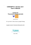
Node indexes of the nodes belonging to the element. The node order is n1 n2 n3. Line 3 is repeated for each of the elements, with the total number of repeated lines matching the entry in line 2. Note that the order of the nodes in the element definition dictate the direction of the element normal. Figure 1 shows the relation between the node order and the direction of the element normal. Element normals should point into the acoustic medium. Figure 1 Element Node Order and Element Normal Direction Example: [surface elements] 72000 1 1 1 2 3 2 2 4 5 3 2 5 3 4 3 5 6 … 72000 36002 546 756 Boundary Conditions Definition File The boundary conditions (BCs) are defined in this file. The file begins with a header line: [params] followed by the number of mesh elements expected in the BC definition file. 7 The actual BCs are defined using either element groups of conditions using
[boundary #] or individual element definitions using
[per element]
. For each group, 6 BC parameters must be defined, plus the index to the elements the BC is to be applied to. The 6 BC parameters define the values of a b and c to fulfil the bc equation: Group Based Boundary Condition Each boundary condition group follows the following format: Line 1.
Line 2.
Line 3.
Line 4.
Opening header for boundary definition
[boundary #].
The # is replaced by an integer counting the number of boundary sets, starting from 1. Column #1
Real part of a Column #2
Imaginary part of a Column #3
Real part of b Column #4
Imaginary part of b Column #5
Real part of c Column #6
Imaginary part of c either
{m – n}
or just
#
. Use the former version to define a range of elements from the value m to the value n with a step of 1, for which the BC definition will apply to, or the later to define an individual element index. Only one element per row can be defined. Can be used to define another range of element indices or individual elements. Any number of lines is permitted. Format is the same as Line 3. Example: [boundary 1] 1.2e+01 0.0e+00 1.0e+00 0.0e+00 0.0e+00 0.0e+00 {1 70999} 71000 72000 {80000 90100} [boundary 2] 0.0e+00 0.0e+00 1.0e+00 0.0e+00 1.2e+01 0.0e+00 {91001 91999} The example defines 2 boundary condition set. In boundary condition set #1, the boundary conditions for elements 1 to 70999, 71000, 72000 and elements 80000 to 90100 inclusive are defined as: ℜ
(a)=12
ℑ
(a)=0, ℜ
(b)= 1ℑ
(b)=0, ℜ
(c)= 0
ℑ
(c)=0, Boundary condition set #2 applies to elements 91001 to 91999 inclusively and: 8 ℜ
(a)= 0
ℑ
(a)=0, ℜ
(b)= 1ℑ
(b)=0, ℜ
(c)= 12
ℑ
(c)=0, Element Based Boundary Condition Each element based boundary condition follows the following format: Line 1.
Line 2.
Line 3.
Opening header for boundary definition
[per element]. Column #1
Element index number Column #2
Real part of a Column #3
Imaginary part of a Column #4
Real part of b Column #5
Imaginary part of b Column #6
Real part of c Column #7
Imaginary part of c Repetition of Line 2 for each element that should have its own unique boundary condition values. Example: [per element] 1 1.2e+01 0.0e+00 1.0e+00 0.0e+00 0.0e+00 0.1e+00 2 1.4e+01 0.2e+00 2.0e+00 0.0e+00 3.0e+00 0.0e+00 3 1.5e+01 0.0e+00 4.0e+00 0.0e+00 0.0e+00 0.5e+00 Point Source Definition File Source points for the model are defined in this file. The format is as follows: Line 1.
Line 2.
Line 3.
Line 4.
Opening header source point definition
[source points]. Integer indicating the number of source points defined. The first source point definition. 5 columns of data Column #13 the X, Y, Z coordinates of the source point. Column #4
the excitation magnitude of the point. Column #5
the set number. Repetition of Line 3 for additional source points in the model.
If multiple point sources are to be defined in the model, some simulation time can be saved by using some of the processing information generated by the first point source solution process as a starting point for the other point source solutions. Using point source sets enables this time saving feature. The th
5
column is used to define the set number for the source point. For example, if two point sources are defined, and each point source is given a unique set number, then for the defined model set up, two sets of results will be generated; one set for the first point source set, and a second for the second set. In addition, more than one point source can be active in any one solution, so for example two points sources can be generating sound in one point source set solution, and a third source used in a second point source set defined, which can use some information from the first solution. Example: [source points] 3 9 1.85 0.0 0.0 1.0 1 0.0 1.85 0.0 2.0 1 0.0 0.0 2.0 3.0 2 In the example, 2 point source sets are defined. Point sources #1 and #2 are active together in the first set, and only source #3 is active in the second. Additional Pressure Evaluation Points File Additional points can be defined in the model and the pressure values at those points determined. The format is as follows: Line 1.
Line 2.
Line 3.
Line 4.
Opening header for point definition
[points]. The number of additional points defined. The line contains the data for the individual point definition. Column #1
The Index of the additional node. Columns #24 The X, Y, Z coordinate values of the point’s location Repetition of Line 3 for the other additional points in the model. Example: [points] 1001 1 8.2503940255332464e01 3.6914711540626879e02 8.7060168177320063e01 2 8.8955123432450323e01 7.6004447071884829e01 2.6651642358672506e01 3 6.3477662714762417e01 6.0683686156698717e02 1.0165510925976722e+00 4 1.5891833519859105e01 7.2676343983004321e01 9.4157308015050600e01 5 6.5328920561516027e02 7.9650510685391529e01 8.9516017946169824e01 6 9.8874614903923941e01 4.8091679425128359e01 4.8072870703458381e01 7 1.1743271206522803e01 9.5674506673556770e01 7.1473661961183910e01 8 3.5447478252811720e01 6.4649628623782629e01 9.4677884452090666e01 … 1001 1.8685852357417512e01 7.8022056971639153e01 8.9237870590860069e01 . Surface Pressure Results File The calculated surface pressure result data is written by the solver to this file. The format is as follows: Line 1.
Line 2.
Line 3.
Line 4.
Opening header for pressure data is
[pressure] Column #1
The number of nodes in the model Column #2
The number of sets in the pressure data. The number of sets matches the number of point source sets defined. 4 columns of data giving the pressure values for an individual node for a particular point source set. Column #1
Point source set number Column #2
Node index number Column #3
Real value of the complex pressure Column #4
Imaginary value of the complex pressure. Repetition of Line 3 for all nodes in the model, an source point sets. Example: [pressure] 36002 2 1 1 2.2378046324680764e01 2.8953353342433241e01 10 1 2 2.2611536771481261e01 2.8876616870832311e01 1 3 2.2767570882273033e01 2.8881985260275295e01 1 4 2.3079992941678174e01 2.8627118903233945e01 … 1 36002 2.3395338707126051e01 2.8677275864187446e01 2 1 2.3086005478015029e01 2.8748785089343648e01 … 2 36002 2.3763053126378531e01 2.8197914571170829e01 Additional Points Pressure Results File The pressure data results for the defined additional points are contained in this file. The file format is as follows: Line 1.
Line 2.
Line 3.
Line 4.
Opening header
[pressure in points] Column #1
Number of pressure points in the file Column #2
Number of source point sets in the file 4 columns of data giving the pressure values for an individual node for a particular point source set. Column #1
Point source set number Column #2
Node index number Column #3
Real value of the complex pressure Column #4
Imaginary value of the complex pressure. Repetition of Line 3 for all nodes in the model, and source point sets. Example: [pressure in points] 1000 2 1 1 2.2378046324680764e01 2.8953353342433241e01 1 2 2.2611536771481261e01 2.8876616870832311e01 1 3 2.2767570882273033e01 2.8881985260275295e01 1 4 2.3079992941678174e01 2.8627118903233945e01 … 1 1000 2.3395338707126051e01 2.8677275864187446e01 2 1 2.3086005478015029e01 2.8748785089343648e01 … 2 1000 2.3763053126378531e01 2.8197914571170829e01 11