1
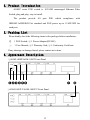
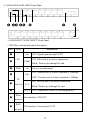
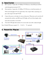
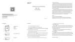
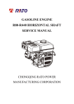
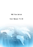
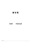
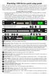
AOM-P Series POE Fiber Switch User Manual V1.02 [键入文字] 1. Precautions Please read the manual carefully before installing and using the switch. Disassembling any parts of the product without authorization is strictly prohibited. Please put the product into the standard cabinet, placed in ventilated and dry place when using. The product is suitable for indoor application. If it must work outdoor, please note the grounding and light protection, so as to avoid damage by lightning strike. Please consider the heat dissipation of the product when installing. Around the device should be reserved enough space (more than 10cm) for proper cooling. Do not use the product closely to the device which has large heat productivity (such as power supply etc.). No water-resistant function, if used outdoor, please put the products above the ground more than 80cm. Please use 48V power supply, Do Not use mismatching power supply. POE power supply must meet the power requirement of the connecting devices. Please cut off the power first before plugging the power adaptor. 1 2. Product Introduction AOM-P series POE switch is 10/100M unmanaged Ethernet Fiber Switch, plug and play, easy to install. The product provide 4/8 port POE which compliance with IEEE802.3af/IEEE802.3at standard and POE power up to 15.4W/30W for each port. 3. Packing List Please kindly check the following items in the package before installation: ① 1 POE Switch; ② 1 Power Adaptor(DC48V); ③ 1 User Manual; ④ 1 Warranty Card; ⑤ 1 Conformity Certificate If any shortage or damage found, please contact us in time. 4. Appearance Description ①AOM-1400P/AOM-1400T Front Panel ❶❷❸❹❺❻ ❼ ❽ ②AOM-1400P-T/AOM-1400T-T Front Panel 2 ③ AOM-1800P/AOM-1800T Front Panel ❶ ❷❸ ❹❺ ❻ ❼ ❽ ④AOM-1800P-T/AOM-1800T-T Front Panel ⑤POE fiber switch patch panel description NO. LED ❶ ❷ ❸ Explanation On FX “ON” Signal input through FX/TX “ON” Fiber link is in correct connection. LINK “Blink” Packet goes through Fx end. PWR On Power is on and normal. “ON” Transfer rate of electric interface is 100Mbps ❹ 100 “OFF” Transfer rate of electric interface is 10Mbps TP ❺ Link/Act ❻ ❼ ❽ “ON” Electric link is in correct connection. L/A “Blink” Packet goes through Tx end. TP1-8 “ON” Connected PD device, working properly. Fiber Fiber interface: ST/SC/FC Interface RJ45 RJ45 interface: Twisted-pair CAT5 Interface 3 5. Installation ① RJ45 interface: Connect the 10/100Base-TX PD device to the RJ45 jack of POE switch through twisted-pair CAT5 ② Fiber interface: Connect the 10/100Base-TX PD device to the fiber interface of POE switch through SC/FC/ST optical fiber. Note: Optical fiber connecting is in pair, when single A-B, dual TX-RX. ③ Connect the power cord, plug it in, turn on the power. When turn on, the switch will automatically initialize, and RJ45 port LED lights will be off after bright, which means the restoration is successful. ④ Check the LED lights that remains lit or not to make sure cable connected right. Note: Default POE power supply 1/2+、3/6-(4/5+、7/8- optional). 6. Connection Diagram 4 AOA TECHNOLOGY CO., LIMITED Add: 5/F North, Chuangyu Jindi Technology Park, No.1222 Guanguang Rd. Longhua New District, Shenzhen, China Tel: +86 755 83553915 Web: www.aoatech.com 5