1
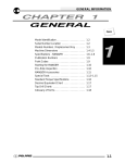
CHAPTER 10 ELECTRICAL Special Tools . . . . . . . . . . . . . . . . . . . . . . . . . . . . . . . . . . . Headlamp Service, 1998/99 . . . . . . . . . . . . . . . . . . . . . . Indicator Lamp Service . . . . . . . . . . . . . . . . . . . . . . . . . . Timing Check Procedure . . . . . . . . . . . . . . . . . . . . . . . . Typical Ignition Timing Curve . . . . . . . . . . . . . . . . . . . . . Flywheel Identification . . . . . . . . . . . . . . . . . . . . . . . . . . . 250 Watt Alternator, Exploded View . . . . . . . . . . . . . . . Ignition System Testing . . . . . . . . . . . . . . . . . . . . . . . . . . Ignition System Troubleshooting . . . . . . . . . . . . . . . . . . Battery Service . . . . . . . . . . . . . . . . . . . . . . . . . . . . . . . . . Charging System Testing . . . . . . . . . . . . . . . . . . . . . . . . Starter System Troubleshooting . . . . . . . . . . . . . . . . . . Starter System Testing . . . . . . . . . . . . . . . . . . . . . . . . . . Starter Motor Service . . . . . . . . . . . . . . . . . . . . . . . . . . . Starter Drive . . . . . . . . . . . . . . . . . . . . . . . . . . . . . . . . . . . Speed Limiter System/Troubleshooting . . . . . . . . . . . . AWD Testing . . . . . . . . . . . . . . . . . . . . . . . . . . . . . . . . . . . Coolant Sensor Tests . . . . . . . . . . . . . . . . . . . . . . . . . . . Fan Control Circuit Operation . . . . . . . . . . . . . . . . . . . . Fan Motor Current Draw Test . . . . . . . . . . . . . . . . . . . . . Electronic Throttle Control System Operation . . . . . . Wiring Diagrams . . . . . . . . . . . . . . . . . . . . . . . . . . . . . . . . 10.1 10.2-10.3 10.4 10.5 10.6 10.7 10.8 10.9-10.10 10.11 10.12-10.15 10.16-10.18 10.19 10.20 10.21-10.25 10.26 10.27-10.29 10.30 10.31 10.32 10.33 10.34 10.35-10.36 10 ELECTRICAL SPECIAL TOOLS Fluke 73 Multitester or Tektronix DMM 155 . . . PN 2870659 Strobe Timing Light . . . . . . . . . . . . . . . . . . . . . . . PN 2870630 Hydrometer . . . . . . . . . . . . . . . . . . . . . . . . . . . . . . PN 2870836 Tachometer . . . . . . . . . . . . . . . . . . . . . . . . . . . . . . PN 8712100 or PN 8712500 ELECTRICAL SERVICE NOTES Keep the following notes in mind when diagnosing an electrical problem. SRefer to wiring diagram for stator and electrical component resistance specifications. SWhen measuring resistance of a component that has a low resistance value (under10 Ohms), remember to subtract meter lead resistance from the reading. Connect the leads together and record the resistance. The resistance of the component is equal to tested value minus the lead resistance. SBecome familiar with the operation of your meter. Be sure leads are in the proper jack for the test being performed (i.e. 10A jack for current readings). Refer to the Owner’s manual included with your meter for more information. SVoltage, amperage, and resistance values included in this manual are obtained with a Fluke 73 Digital Multimeter or a Tektronix DMM155. Both of these meters are acceptable for use when diagnosing electrical problems. Readings obtained with other meters may differ. SPay attention to the prefix on the multimeter reading (K, M, etc.) and the position of the decimal point. SFor resistance readings, isolate the component to be tested. Disconnect it from the wiring harness or power supply. 10.1 ELECTRICAL HEADLIGHT ADJUSTMENT The high beam headlight can be adjusted to any position desired by turning the four screws at the outer corners of the lamp housing. Use the following procedure: 1. Place the vehicle on a level surface with the headlight approximately 25’ (7.6 m) from a wall. 2. Measure the distance from the floor to the center of the headlight and make a mark on the wall. 3. Shift transmission to neutral, start engine and turn headlight switch to high beam. 4. Observe headlight aim. The most intense part of the headlight beam should be aimed 2 (5.1 cm) below the mark placed on the wall in step 2. NOTE: Rider weight must be included on the seat. For machines with separate low beam lights, the drop should be 8 (20.3 cm) in 25’. 5. Adjust screws at outer corners of lamp housing to achieve proper aim. HEADLIGHT LAMP REPLACEMENT WARNING: Due to the nature of ATVs and where they are ridden, headlight lenses become dirty. Frequent washing is necessary to maintain lighting quality. Riding with poor lighting can result in severe injury or death. 1. Remove the seat. 2. Remove the plastic panel surrounding the upper portion of the gas tank by first removing the gas tank cap. 3. Remove the Phillips screws on either side of the panel at the junction of this panel, the lower panels, and the rear of the front fenders. 4. Remove the Phillips screws on either side of the rear of the upper panel which were revealed by the removal of the seat. 5. Remove the door on the front of the ATV covering the radiator cap by turning the fastener one quarter turn. 6. Disengage the tabs at the front of the upper panel where they snap into the lower panel surrounding the headlight assembly. Also disengage the tabs on the upper panel which engage with the lower triangular panels on either side of the machine. Lift off the upper panel and set it aside. 10.2 25’ (7.6 m) Lamp Center Height 2 (5.1 cm) ELECTRICAL HEADLIGHT LAMP REPLACEMENT, CONT. 7. Reinstall the gas tank cap. 8. Remove the panel surrounding the headlight by removing the Phillips screws from either side of this panel. Also remove the two Torx screws at the rear of this panel. 9. Ease the panel forward and up to allow you to reach the socket connected to the headlight lamp. 10.Carefully unplug the socket from the lamp. Remove the panel and set it aside. CAUTION: Do not service while headlight is hot. Serious burns may result. 11. Stand the panel containing the headlight assembly on end to allow access to the back of the headlight assembly. 12.Disengage the wire bail holding the headlight lamp in place and move it out of the way. 13.Grasp the base of the lamp and lift it out. 14.Reverse the previous steps to replace the lamp and reassemble the panels. 13 NOTE: Do not touch a halogen lamp with bare fingers. Oil from your skin leaves a residue, causing a hot spot which will shorten the life of the lamp. Hold the lamp by the base. 10.3 ELECTRICAL TAILLIGHT/BRAKELIGHT LAMP REPLACEMENT If the taillight/brakelight does not work the lamp may need to be replaced. 1. From the rear of the taillight remove two screws holding lens cover in place and remove lens cover. Lens Cover 2. Remove lamp and replace it with recommended lamp. Apply dielectric grease PN 2871027. 3. Reinstall the lens cover removed in step 1. 4. Test the taillight/brakelight to see that it’s working. INDICATOR LAMP REPLACEMENT 1. With a small, flat screwdriver gently pry loose the indicator light cover. 2. Using a small flexible tube (such as an oil delivery hose) grasp the burned out lamp and remove it. 3. Replace the removed lamp with a Polaris PN 4030042. 4. Replace the indicator light cover. NOTE: Check all lights daily for proper operation replace or repair if necessary. 10.4 Bulb ELECTRICAL TIMING CHECK PROCEDURE 1. The ignition timing check hole is in the starter recoil/magneto housing. Remove the check plug. NOTE: The ignition timing marks are stamped on the outside of the flywheel. Ignition timing must be inspected with the engine at room temperature (68F / 20 C). 2. With the transmission in neutral, start the engine and set engine speed to 3500 200 RPM. 3. Direct the timing light at the ignition timing check hole and check the ignition timing. NOTE: Do not allow the engine to warm up. The timing will retard approximately 2 when the engine is warm. If the ignition timing is not within the specified range, adjust the stator plate position as described below. Flywheel Rotation 32 Timing Pointer 30 28 EH50PL Stator Adjustment 1. Remove the magneto housing. 2. Remove the flywheel. 3. Loosen the stator plate screws and adjust the stator plate position. NOTE: Moving the stator plate clockwise retards (delays) the ignition timing. Moving the plate counterclockwise advances it. 10.5 ELECTRICAL TYPICAL IGNITION TIMING CURVE * Actual advance point may vary by several hundred RPM either above or below 3500. Use the point of maximum advance when checking ignition timing. MAXIMUM ADVANCE POINT (*) IGNITION TIMING (DEGREES) B.T.D.C. 30 28 26 24 22 20 18 16 14 12 10 8 0 10.6 1000 2500 3000 3500 4000 4500 5000 5500 6000 ELECTRICAL FLYWHEEL IDENTIFICATION B A Flywheel Identification Stamp Location The flywheel can be identified by the stamp mark in location A or B. Refer to “I.D.” location in chart below. Do not use the cast mark to determine flywheel application. Engine Application EH50PLE06 Type Cast Stamp Comment Flywheel I.D. Stamp FF9706 FF97 06 250W A 10.7 ELECTRICAL COMPONENTS OF EH50PL 250 WATT ALTERNATOR NOTE: CDI boxes may look the same but have different internal circuitry. Be sure to always use the correct CDI box part number. Ignition Kill Wire (Black) Ignition Coil Primary Winding Resistor Cap Meter 3 Wire (Blk/R, Red, Grn) .3 200 W (3 wires) 250 W (2 Wires) Coil Lead Meter Ignition Coil 5k Meter Pulse Coil (Trigger) Air Gap: .016-.040 (.4 - 1.0 mm) CDI Box 6300 Ignition Coil Secondary Winding Check coil mount for good ground to engine (0-.2 ) Stator Plate Magnetic Switch Ignition Exciter Coils Battery Charging Coils Flywheel and Ring Gear Casting. Refer to page 10.7 for identification. 10.8 Refer to wiring diagrams for specified stator coil resistance ELECTRICAL IGNITION SYSTEM Whenever troubleshooting an electrical problem you should first check all terminal connections to be sure they are clean and tight. Also be sure that colors match when wires are connected. Use the following pages as a guide for troubleshooting. The resistance values are also given on the specification pages. Condition: No Spark or intermittent spark Replace Spark Plug Disconnect the black wire at the CDI module to isolate the ignition from the kill system. -Test the ignition switch, engine stop switch, and speed limiter circuit for shorts to ground. -Check connectors for moisture, wire color matching or corrosion. Yes Does it have spark? No Disconnect the exciter coil and pulse coil connector from the CDI module. Measure the resistance of the exciter coil and pulse coil. Refer to the exploded view on page 10.8 or the wiring schematic for meter connections and specifications. Compare results to the specifications on the exploded views. Are all within specifications? Inspect connectors, wiring and grounds to the component in question. Replace the component if a wiring problem cannot be found. No Yes Check coil ground connection between engine and coil mount using an ohmmeter. The coil mount should have good continuity to ground on the engine (0-.2 . No Clean coil mounting area. Repair ground wire connections. Yes Disconnect and check the secondary coil. Resistance values should be: Primary Side - Primary Wire Tab to Ground (on coil mount or engine): .3 to .5 Ohms Secondary Side High Tension Wire to engine ground- Cap installed - 11,300 Cap removed - 6300 Are these values within specs? No Replace the ignition coil. Yes If all of the above tests are within specifications, and all grounds, connections, and wire color coding have been inspected, perform voltage output tests on following page or replace the CDI module. 10.9 ELECTRICAL CRANKING OUTPUT TEST WITH PEAK READING VOLTMETER The following peak voltage tests will measure the amount of output directly from each component. A peak reading voltmeter must be used to perform the tests. A variety of peak reading adaptors are commercially available for use with the Fluke 73 Digital Multitester, Tektronix DMM155, and other digital VOMs which will allow peak voltage tests to be performed accurately. Follow the directions provided with the adaptor. All measurements are indicated in DC Volts. Readings obtained without a peak reading adaptor will be significantly different. Disconnect the stator connectors from the CDI module. Test output from exciter coil, pulse (trigger) coil, and compare to the chart. The following measurements are obtained when cranking the engine with the electric starter, spark plug installed. The starter system must be in good condition and the battery fully charged. 250 Watt 4 Stroke Coil Connect Meter Wires To: Reading (With Peak Reading Volt meter) Exciter 1 Black/Red and Red 140 DCV Exciter 2 Black/Red and Green 140 DCV Exciter 3 Green and Red 5 DCV Pulse (Trigger) White/Red and White 2.5 DCV CDI OUTPUT TEST USING PEAK READING ADAPTOR Re-connect all CDI wires to stator wires. Disconnect CDI module wire from ignition coil primary terminal. Connect one meter lead to engine ground and the other to the ignition coil primary wire leading from the CDI module. Crank engine and check output of CDI wire to coil (130 DCV). Reconnect coil wire to CDI. Output w/ Peak output tester 130 DCV Average Output w/ Digital Voltmeter 20 DCV 10.10 ELECTRICAL IGNITION SYSTEM TROUBLESHOOTING No Spark, Weak or Intermittent Spark SSpark plug gap incorrect SFouled spark plug SFaulty spark plug cap or poor connection to high tension lead SRelated wiring loose, disconnected, shorted, or corroded SEngine Stop switch or ignition switch faulty SETC switch misadjusted or faulty STerminal board or connections wet, corroded SPoor ignition coil ground (e.g. coil mount loose or corroded) SFaulty stator (measure resistance of all ignition related windings) SIncorrect wiring (inspect color coding in connectors etc) SFaulty ignition coil winding (measure resistance of primary and secondary) SWorn magneto (RH) end Crankshaft bearings SSheared flywheel key SFlywheel loose or damaged STrigger coil air gap too wide (where applicable) - should be .016-.040 (.4-1.0 mm) SExcessive crankshaft runout on magneto (RH) end - should not exceed .0024 SFaulty CDI module** 10.11 ELECTRICAL INITIAL BATTERY SERVICE WARNING Battery electrolyte is poisonous. It contains sulfuric acid. Serious burns can result from contact with skin, eyes or clothing. Antidote: External: Flush with water. Internal: Drink large quantities of water or milk. Follow with milk of magnesia, beaten egg, or vegetable oil. Call physician immediately. Eyes: Flush with water for 15 minutes and get prompt medical attention. Batteries produce explosive gases. Keep sparks, flame, cigarettes, etc. away. Ventilate when charging or using in an enclosed space. Always shield eyes when working near batteries. KEEP OUT OF REACH OF CHILDREN. WARNING: The gases given off by a battery are explosive. Any spark or open flame near a battery can cause an explosion which will spray battery acid on anyone close to it. If battery acid gets on anyone, wash the affected area with large quantities of cool water and seek immediate medical attention. To ensure maximum service life and performance from a new battery, perform the following steps. NOTE: Do not service the battery unless it will be put into regular service within 30 days. After initial service, add only distilled water to the battery. Never add electrolyte after a battery has been in service. NOTE: New Battery: Battery must be fully charged before use or battery life will be significantly reduced 10-30% of batterys’ full potential. 1. Remove vent plug from vent fitting. 2. Fill battery with electrolyte to upper level marks on case. 3. Set battery aside and allow it to cool and stabilize for 30 minutes. 4. Add electrolyte to bring level back to upper level mark on case. NOTE: This is the last time that electrolyte should be added. If the level becomes low after this point, add only distilled water. 5. Charge battery at 1/10 of its amp/hour rating. Examples: 1/10 of 9 amp battery = .9 amp; 1/10 of 14 amp battery = 1.4 amp; 1/10 of 18 amp battery = 1.8 amp (recommended charging rates). 6. Check specific gravity of each cell with a hydrometer to assure each has a reading of 1.270 or higher. BATTERY TERMINALS/TERMINAL BOLTS Use Polaris corrosion resistant dielectric grease (PN 2871027) on battery bolts. See Battery Installation on page 10.13. 10.12 ELECTRICAL BATTERY INSPECTION/REMOVAL The battery is located under the left rear fender. Inspect the battery fluid level. When the battery fluid nears the lower level, the battery should be removed and distilled water should be added to the upper level line. To remove the battery: 1. Disconnect holder strap and remove cover. 2. Disconnect battery negative (-) (black) cable first, followed by the positive (+) (red) cable. Maintain between upper and lower level marks CAUTION Whenever removing or reinstalling the battery, disconnect the negative (black) cable first and reinstall the negative cable last! 3. Disconnect the vent hose. 4. Remove the battery. 5. Remove the filler caps and add distilled water only as needed to bring each cell to the proper level. Do not overfill the battery. To refill use only distilled water. Tap water contains minerals which are harmful to a battery. Do not allow cleaning solution or tap water to enter the battery. It will shorten the life of the battery. 6. Reinstall the battery caps. BATTERY INSTALLATION 1. Clean battery cables and terminals with a stiff wire brush. Corrosion can be removed using a solution of one cup water and one tablespoon baking soda. Rinse will with clean water and dry thoroughly. 2. Reinstall battery, attaching positive (+) (red) cable first and then the negative (-) (black) cable. Coat terminals and bolt threads with Polaris dielectric grease PN 2871027. 3. Install clear battery vent tube from vehicle to battery vent. WARNING: Vent tube must be free from obstructions and kinks and securely installed. If not, battery gases could accumulate and cause an explosion. Vent should be routed away from frame and body to prevent contact with electrolyte. Avoid skin contact with battery electrolyte, severe burns could result. If electrolyte contacts the vehicle frame, corrosion will occur. 4. Route cables so they are tucked away in front and behind battery. 5. Reinstall battery cover and holder strap. Do not start the engine with the battery disconnected. Vehicle lamps will burn out if battery is disconnected during vehicle operation. Also, the reverse speed limiter can be damaged. BATTERY TESTING Whenever a service complaint is related to either the starting or charging systems, the battery should be checked first. Following are three tests which can easily be made on a battery to determine its condition: OCV Test, Specific Gravity Test and Load Test. OCV - OPEN CIRCUIT VOLTAGE TEST Battery voltage should be checked with a digital multitester. Readings of 12.6 or less require further battery testing and charging. See charts and Load Test on page 10.14. NOTE: Lead-acid batteries should be kept at or near a full charge as possible. Electrolyte level should be kept between the low and full marks. If the battery is stored or used in a partially charged condition, or with low electrolyte levels, hard crystal sulfation will form on the plates, reducing the efficiency and service life of the battery. 10.13 ELECTRICAL SPECIFIC GRAVITY TEST A tool such as a Battery Hydrometer (PN 2870836) can be used to measure electrolyte strength or specific gravity. As the battery goes through the charge/discharge cycle, the electrolyte goes from a heavy (more acidic) state at full charge to a light (more water) state when discharged. The hydrometer can measure state of charge and differences between cells in a multi-cell battery. Readings of 1.270 or greater should be observed in a fully charged battery. Differences of more than .025 between the lowest and highest cell readings indicate a need to replace the battery. OPEN CIRCUIT VOLTAGE State of charge Conventional Lead-acid YuMicron Type 100% Charged 75% Charged 50% Charged 25% Charged 0% Charged 12.60V 12.40V 12.10V 11.90V less than 11.80V 12.70V 12.50V 12.20V 12.0V less than 11.9V Polaris PN 2870876 1.10 Detail A 1.15 1.20 1.25 SPECIFIC GRAVITY State of charge* Conventional lead-acid YuMicron Type 100% Charged 75% Charged 50% Charged 25% Charged 0% Charged 1.265 1.210 1.160 1.120 less than 1.100 1.275 1.225 1.175 1.135 less than 1.115 1.30 * At 80_F NOTE: Subtract .01 from the specific gravity reading at 40_ F. LOAD TEST CAUTION: Remove spark plug high tension leads and connect securely to engine ground before proceeding. NOTE: This test can only be performed on machines with electric starters. This test cannot be performed with an engine or starting system that is not working properly. A battery may indicate a full charge condition in the OCV test and the specific gravity test, but still may not have the storage capacity necessary to properly function in the electrical system. For this reason, a battery capacity or load test should be conducted whenever poor battery performance is encountered. To perform this test, hook a multitester to the battery in the same manner as was done in the OCV test. The reading should be 12.6 volts or greater. Engage the electric starter and view the registered battery voltage while cranking the engine. Continue the test for 15 seconds. During this cranking period, the observed voltage should not drop below 9.5 volts. If the beginning voltage is 12.6 or higher and the cranking voltage drops below 9.5 volts during the test, replace the battery. 10.14 ELECTRICAL OFF SEASON STORAGE To prevent battery damage during extended periods of non-use, the following basic battery maintenance items must be performed: SRemove the battery from the machine and wash the case and battery tray with a mild solution of baking soda and water. Rinse with lots of fresh water after cleaning. NOTE: Do not get any of the baking soda into the battery or the acid will be neutralized. SUsing a wire brush or knife, remove any corrosion from the cables and terminals. SMake sure that the electrolyte is at the proper level. Add distilled water if necessary. SCharge at a rate no greater than 1/10 of the battery’s amp/hr capacity until the electrolyte’s specific gravity reaches 1.270 or greater. SStore the battery either in the machine with the cables disconnected, or put it on a piece of wood and store in a cool place. NOTE: Stored batteries lose their charge at the rate of 1% per day. They should be recharged to a full charge every 30 to 60 days during a non-use period. If the battery is stored during the winter months the electrolyte will freeze at a higher temperature as the battery discharges. The chart at right indicates freezing points by specific gravity. CHARGING PROCEDURE Charge the battery with a charger no larger than 1/10 of the battery’s amp/hr rating for as many hours as needed to raise the specific gravity to 1.270 or greater. Electrolyte Freezing Points Specific Gravity of Electrolyte Freezing Point 1.265 -75 F 1.225 -35 F 1.200 -17 F 1.150 +5 F 1.100 +18 F 1.050 +27 F 1. Install battery in vehicle with positive terminal toward the front. Coat threads of battery bolt with Polaris corrosion resistant dielectric grease. Polaris Dielectric Grease PN 2871329 (Nyogel) WARNING To avoid the possibility of explosion, connect positive (red) cable first and negative (black) cable last. 2. Connect battery cables. 3. After connecting the battery cables, install the cover on the battery and attach the hold down strap. 4. Install clear battery vent tube from vehicle to battery vent. WARNING: Vent tube must be free from obstructions and kinks and securely installed. If not, battery gases could accumulate and cause an explosion. Vent should be routed away from frame and body to prevent contact with electrolyte. Avoid skin contact with battery electrolyte, severe burns could result. If electrolyte contacts the vehicle frame, corrosion will occur. 5. Route cables so they are tucked away in front and behind battery. 10.15 ELECTRICAL CHARGING SYSTEM TESTING Whenever charging system problems are suspected, proceed with the following system check. Using a multitester set on D.C. volts, measure the battery open circuit voltage (See page 10.13). It should be 12.4 volts or more. Is it? No Remove the battery and properly service. Reinstall the fully charged battery or a fully charged shop battery. Yes Meter Setting: DC Volts With the transmission in neutral, start the engine and increase RPM to between 3000 and 4000. Read battery voltage with the multitester. Readings should be between 13.0 and 14.6 V D.C. Yes Check Key off Current Draw Are they? No Meter Setting: DC Amps Perform system “Break Even Amperage” test outlined on page 10.17. Yes Does charging occur as specified? No Meter Setting: AC Amps Disconnect the Yellow/Red, Yellow, and Yellow/Brn (if applicable) wires from the regulator/rectifier. Using a multitester, perform an Alternator Output (AC amp) test. See test procedure on page 10.18 for procedure. Is output above 5 amps? No Check for owner modification, and discuss operating habits. The battery will continually discharge if operated below the “Break Even” RPM. Continued problems would call for battery inspection. Inspect the wiring harness between the panel and the stator for damage. If no damage is found, remove the recoil and flywheel. Inspect the flywheel magnets, stator coils and stator wire harness for damage. Repair or replace any damaged components. Yes Meter Setting: DC Volts Reconnect the alternator wires. Note: Red wire must be connected to harness. Battery voltage must be present on red wire terminal on harness side of voltage regulator connector. Is it? Yes If all of the previous tests indicate a good condition, but the charging voltage does not rise above battery voltage at the connector or terminal board, replace the voltage regulator. 10.16 No Check regulator/rectifier connections and ground, battery connections, circuit breaker and connecting wires. Repair or replace faulty wiring or components. ELECTRICAL CURRENT DRAW - KEY OFF CAUTION: Do not connect or disconnect the battery cable or ammeter with the engine running. Damage will occur to light bulbs and speed limiter. Connect an ammeter in series with the negative battery cable. Check for current draw with the key off. If the draw is excessive, loads should be disconnected from the system one by one until the draw is eliminated. Check component wiring as well as the component for partial shorts to ground to eliminate the draw. Current Draw - Key Off: Maximum of .02 DCA (20 mA) CHARGING SYSTEM “BREAK EVEN” TEST CAUTION: Do not connect or disconnect the battery cable or ammeter with the engine running. CAUTION: Never use the electric starter with the ammeter connected, or damage to the meter or meter fuse may result. Do not run test for extended period of time. Do not run test with high amperage accessories. The “break even” point of the charging system is the point at which the alternator overcomes all system loads (lights, etc.) and begins to charge the battery. Depending on battery condition and system load, the break even point may vary slightly. The battery should be fully charged before performing this test. SConnect an ammeter (set to DC amps) in series between the negative battery cable and terminal. SConnect a tachometer according to manufacturer’s instructions. SWith engine off and the key and kill switch in the ON position, the ammeter should read negative amps (battery discharge). Reverse meter leads if a positive reading is indicated. SShift transmission into neutral. Start engine with recoil only. SIncrease engine RPM while observing ammeter and tachometer. SNote RPM at which the battery starts to charge (ammeter indication is positive). SWith lights and other electrical load off, this should occur at approximately 1500 RPM or lower. STurn the lights on and lock parking brake to keep brake light on. Current Drain Inspection Key Off + -YB14A Less Than 9 mA Do not use electric start. SRepeat test, observing ammeter and tachometer. With lights on, charging should occur at or below 2000 RPM. 10.17 ELECTRICAL ALTERNATOR OUTPUT TEST (AC AMP) This test measures AC amperage from the alternator. SMaximum alternator output will be indicated on the meter. It is not necessary to increase engine RPM above idle. SPlace the red lead on the tester in the 10A jack. STurn the selector dial to the AC amps (Aμ) position. SConnect the meter leads to the Yellow and Yellow/Red wires leading from the alternator. SStart the engine and let it idle. Reading should be a minimum of 7A at idle. CAUTION: This test simulates a “full load” on the alternator. Do not perform this test longer than required to obtain a reading or the alternator stator windings may overheat. 10-15 seconds is acceptable. Alternator Current Output: Minimum of 7 AC Amps To Calculate Available Alternator Output I = P E 250W 12V I = Current in Amps P = Power in Watts E = Electromotive Force (Volts) 10.18 = 20.8 Amps ELECTRICAL STARTER SYSTEM TROUBLESHOOTING Starter Motor Does Not Turn SBattery discharged - low specific gravity SLoose or faulty battery cables or corroded connections (see Voltage Drop Tests) SRelated wiring loose, disconnected, or corroded SPoor ground connections at battery cable, starter motor or starter solenoid (see Voltage Drop Tests) SFaulty starter button SFaulty ignition switch (Do other systems function?) SFaulty starter solenoid or starter motor. SEngine problem - seized or binding (Can engine be rotated easily with recoil starter?) Starter Motor Turns Over Slowly SBattery discharged - low specific gravity SExcessive circuit resistance - poor connections (see Voltage Drop Test below) SEngine problem - seized or binding (Can engine be rotated easily with recoil starter?) SFaulty or worn brushes in starter motor SAutomatic compression release inoperative Starter Motor Turns - Engine Does Not Rotate SFaulty starter drive SFaulty starter drive gears or starter motor gear SFaulty flywheel gear or loose flywheel VOLTAGE DROP TEST The Voltage Drop Test is used to test for bad connections. When performing the test, you are testing the amount of voltage drop through the connection. A poor or corroded connection will appear as a high voltage reading. Voltage shown on the meter when testing connections should not exceed .1 VDC per connection or component. To perform the test, place the meter on DC volts and place the meter leads across the connection to be tested. Refer to the chart on next page to perform voltage drop tests on the starter system. Voltage should not exceed: .1 DC volts per connection 10.19 ELECTRICAL STARTER SYSTEM Condition: Starter fails to turn motor. NOTE: Make sure engine crankshaft is free to turn before proceeding with dynamic testing of starter system. A digital multitester must be used for this test. With the tester on the VDC position, place the tester’s black lead on the battery negative and the red lead on the battery positive. No Reading should be 12.4 or greater. Remove battery and properly service. Install fully charged shop battery to continue test. Yes Disconnect White/Red engagement coil wire from the starter solenoid. Connect tester black wire to battery ground. Connect red tester lead to White/ Red harness wire at solenoid. Turn on ignition switch and depress the starter button. Tester should read battery voltage. Yes Voltage Drop Testing No Check voltage on both sides of circuit breaker, ignition switch/engine stop switch and starter button. The voltage on both sides should be the same. NOTE: The ignition switch and engine stop switch must be on and the starter button depressed. Replace the defective component. Test starter solenoid coil by connecting an ohmmeter between the solenoid red wire and the solenoid mounting plate. Resistance should be 3.4. Check solenoid ground path by measuring resistance between mounting plate and battery negative terminal (-). See Page 10.19 for instructions. Reconnect the solenoid. Connect the tester black lead to the battery positive and the red lead to the solenoid end of the battery-to-solenoid wire. Depress starter button. Reading should be less than .1 V D.C. No Clean the battery-to-solenoid cable ends or replace the cable. No Replace the starter solenoid. No Clean the solenoid-to-starter cable ends or replace the cable. Yes Connect the black tester lead to solenoid end of battery-to-solenoid cable. Connect red tester lead to solenoid end of solenoid-to-starter cable. Depress starter button. Reading should be less than .1 V D.C. Yes Connect the black tester lead to the solenoid end of the solenoid-to-starter cable. Connect the red tester lead to the starter end of the same cable. Depress the starter button. The reading should be less than .1 V D.C. Yes If all of these indicate a good condition, yet the starter still fails to turn, the starter must be removed for static testing and inspection. 10.20 ELECTRICAL STARTER MOTOR DISASSEMBLY NOTE: Use electrical contact cleaner to clean starter motor parts. Some solvents may leave a residue or damage internal parts and insulation. 1. Note the alignment marks on both ends of the starter motor casing. These marks must align during reassembly. 2. Remove the two bolts, washers, and sealing O-Rings. Inspect O-Rings and replace if damaged. 3. Remove brush terminal end of housing while holding other two sections together. 10.21 ELECTRICAL STARTER MOTOR DISASSEMBLY, CONT. 4. Remove shims from armature shaft. NOTE: All shims must be replaced during reassembly. BRUSH INSPECTION/REPLACEMENT 1. Using a digital multitester, measure the resistance between the cable terminal and the insulated brush. The reading should be .3 ohms or less. Measure the resistance between the cable terminal and brush housing. Make sure the brush is not touching the case. The reading should be infinite. 2. Remove nut, flat washer, large phenolic washer, two small phenolic washers, and O-Ring from brush terminal. Inspect the O-Ring and replace if damaged. 3. Remove brush plate and brushes. Measure length of brushes and replace if worn past the service limit. Replace springs if they are discolored or have inadequate tension. 4. Inspect surface of commutator for wear or discoloration. See steps 3-6 of armature testing on page 10.24. 5. Install a new carbon brush assembly in the brush housing. NOTE: Be sure that the terminal bolt insulating washer is properly seated in the housing, and the tab on the brush plate engages the notch in the brush plate housing. Brush Length Service Limit: 5/16 (.8 cm) 10.22 Brush Length ELECTRICAL BRUSH INSPECTION/REPLACEMENT, CONT. 6. Place a wrap of electrical tape on the threads of the terminal bolt to prevent O-Ring damage during reinstallation. 7. Install the O-Ring over the bolt. Make sure the O-ring is fully seated. 8. Remove the electrical tape and reinstall the two small phenolic washers, the large phenolic washer, flat washer, and nut. 10.23 ELECTRICAL ARMATURE TESTING 1. Remove armature from starter casing. Note order of shims on drive end for reassembly. 2. Inspect surface of commutator. excessively worn or damaged. Replace if 3. Using a digital multitester, measure the resistance between each of the commutator segments. The reading should be .3 ohms or less. 4. Measure the resistance between each commutator segment and the armature shaft. The reading should be infinite (no continuity). 5. Check commutator bars for discoloration. Bars discolored in pairs indicate shorted coils, requiring replacement of the starter motor. 6. Place armature in a growler. Turn growler on and position a hacksaw blade or feeler gauge lengthwise 1/8 (.3 cm) above armature coil laminates. Rotate armature 360. If hacksaw blade is drawn to armature on any pole, the armature is shorted and must be replaced. 10.24 ELECTRICAL STARTER ASSEMBLY 1. Place armature in field magnet casing. 2. Place shims on drive end of armature shaft with phenolic washer outermost on shaft. Engage tabs of stationary washer in drive end housing, holding it in place with a light film of grease. 3. Install case sealing O-Ring. Make sure O-Ring is in good condition and not twisted on the case. Lubricate needle bearing and oil seal with a light film of grease, and install housing, aligning marks. 4. Install O-Ring on other end of field magnet casing. Make sure it is in good condition and not twisted on the case. 5. Align casing marks and install housing, pushing back brushes while installing shaft in bushing. 6. Reinstall starter motor housing bolts. Make sure O-Rings are in good condition and seated in groove. 7. Inspect permanent magnets in starter housing. Make sure they are not cracked or separated from housing. CAUTION: Use care when handling starter housing. Do not drop or strike the housing as magnet damage is possible. If magnets are damaged, starter must be replaced. 10.25 ELECTRICAL STARTER DRIVE Pinion Gear - Anti Kick-out Shoe, Garter Spring Replacement If the garter spring is damaged, the overrun clutch may fail to return properly. The replacement spring is PN 7042039. Use either of the following methods to remove and install a new garter spring. Polaris Premium Starter Drive Grease PN 2871460 1. Screw the overrun clutch out to the engaged position on the pinion shaft assembly. Use a small piece of wire with the end bent in a hook and pick the old spring out of its channel. Slide it off the end of the shaft. Slide the new spring over the overrun clutch and into the spring groove. Make sure that the spring is positioned between the shoe alignment pins and the back flange of the anti kick-out shoes. Starter Motor Exploded View Washer Set Carbon Brush Set Rear Brkt Assy Armature 2. Remove the lock ring, end washer, spring retainers and clutch return spring. Screw the overrun clutch off the end of the pinion shaft. Remove the old spring and install a new one. Lightly grease the pinion shaft and reinstall the clutch, spring, retainers, end washer and lock ring in the reverse order. Make sure the end washer is positioned properly so that it will hold the lock ring in its groove. Starter Solenoid Bench Test It is difficult to test the high amp side of the solenoid accurately on the bench. The only test which can be done on the bench is the pull-in coil resistance. The reading should be 3.4 ohms. Rubber Rings Washer O-ring Set Bolt Assy Weight Spring Return Spring 10.26 ELECTRICAL Speed Limiter Module LR ID Number LIMITER SPECIFICATIONS NOTE:The part number is printed on some late model LR modules. Whenever possible, use part number to identify the module. Modules may have same “LR” I.D. number, with different part numbers, terminals, and internal function. Part number is printed on module LIMITER SPECIFICATIONS (Refer to parts manual or microfiche for part number and application.) PART NO. 4060204 TYPE LR44-2 FUNCTION / LIMIT RPM COMMENTS Reverse Limit - 3100 ETC Limit - 1400 10.27 ELECTRICAL REVERSE LIMIT SYSTEM LR44 Reverse Limit System RPM Signal Gry/Or Blk LR44 Gry/Or Gray/Orange Reverse Gear Signal 10.28 RPM Signal Y/R Blk Engine Stop Signal Y/R ELECTRICAL REVERSE SPEED LIMIT SYSTEM APPLY PARKING BRAKE. START ENGINE. SHIFT TO REVERSE GEAR NO REVERSE SPEED LIMIT (LR44 Limit Module) MEASURE DC VOLTS ON R/W WIRE. AT LR44 MODULE TO GROUND N INSPECT R/W WIRE CIRCUIT TO DETERMINE CAUSE N TEST GEAR POSITION INDICATOR SWITCH N TEST REGULATOR AND CHARGING SYSTEM 12 VOLTS DC? Y MEASURE DC VOLTS ON GRY/OR WIRE. AT LR44 MODULE TO GROUND 12 VOLTS DC? Y MEASURE AC VOLTS ON Y/R WIRE. AT LR44 MODULE TO GROUND 3V-9V AC AT IDLE? Y DISCONNECT BLACK WIRE FROM LR44 MODULE AND CONNECT TO GROUND. N TEST WIRING / TEST CDI (BLACK WIRE) ENGINE STOP? Y REPLACE LIMITER MODULE 10.29 ELECTRICAL ALL WHEEL DRIVE SYSTEM All Wheel Drive Activation In Reverse: For AWD in reverse gear, the override button must be pushed in addition to selecting “All Wheel Drive”. Power is delivered through the transmission switch, the override button, the AWD button, and then to the front wheel coils. ALL WHEEL DRIVE (AWD) TESTING The All Wheel Drive (AWD) system is activated when battery voltage is supplied to the front wheel coils. Always check battery voltage when an AWD problem is encountered. Charge battery and check charging system if necessary. If only one wheel hub does not engage, test wheel coil resistance and inspect wheel coil wires for damage. Check for a mechanical problem if resistance measurements are within specifications. 1. 2. 3. 4. Remove front cover to gain access to harness connectors. Turn ignition key on and shift transmission to high gear. Select AWD with AWD button. Check for battery voltage across Gray and Brown wires from backside of hub coil harness connector. NOTE: If power is present and bulb is good, All Wheel Drive lamp will be lit. *If no voltage is present on the Gray wire at harness connector, check the AWD switch and transmission gear position switch. (If voltage is present on the Gray/White wires at harness connector, transmission gear position switch is functioning properly.) Refer to AWD and Transmission Gear Position Switch Testing this section. *If voltage is present: SDisconnect Gray and Brown wheel wires at harness connector and test resistance across the Gray and Brown wires. There should be 25-30 of resistance. STest Gray wire to ground on strut casting. It should be an open circuit (∞). Move wheel coil wiring harness while performing the tests to check for an intermittent open or short. AWD Wheel Coil Resistance Gray to Brown 25-30 No continuity to ground on strut casting) SRepair wiring harness or replace wheel coil if necessary. NO AWD IN REVERSE If AWD functions properly in forward but not in reverse, perform the following tests: NOTE: Override button must be pushed for AWD in reverse. 1. Turn ignition key on and shift transmission to reverse. 2. If reverse lamp is on, the gear position switch is functioning properly. If reverse lamp is off (not illuminated), check the bulb and test gear position switch and related wiring. 3. Check for battery voltage on Purple wire in left hand switch wire harness (leave connector connected). *If battery voltage is present: 4. Press the override button, AWD light should be lit. If not, check for voltage on Gray/White wire at right hand control. SCheck override switch and related wiring if voltage is not present on Gray/White wire(s). If the entire AWD circuit tests correctly, inspect the wheel hubs for a mechanical problem. 10.30 ELECTRICAL COOLANT TEMPERATURE SENSOR TEST (HOT LIGHT) With the ignition switch (and engine stop switch) “ON”, power is delivered to the hot light via the Red/White wire. The Blue/White wire (ground) out of the light socket is connected to the coolant temperature sensor on the cylinder head. In normal operating conditions, the temperature sensor is non-conductive (open). If engine coolant reaches the specified temperature, the sensor becomes conductive completing the ground path for the light. With engine cold, disconnect lead and measure resistance of sensor between connector terminal and ground. There should be no continuity or very high resistance (megohms). To test the “ON” temperature, heat the switch in a water bath to the temperature shown in table below. The switch should become conductive (low resistance) at indicated temperature. Do not immerse switch past the threads or allow switch to contact container when heating. Hot Light On 221 F (105 C) HOT LIGHT CIRCUIT TEST Disconnect temperature sensor wire lead and short it to ground on the cylinder head. Turn key and auxiliary switch to “ON” position. The hot lamp should come on. Check the bulb and related wiring if the lamp does not illuminate. 10.31 ELECTRICAL FAN CONTROL CIRCUIT OPERATION / TESTING The fan switch is located on the radiator. Power is supplied to the fan switch via the Red/White wire when the ignition key and auxiliary shut off switch are ON. When the fan switch reaches the specified temperature, it becomes conductive and sends power to the fan motor. The ground path for the fan motor is through the Brown harness wire. CAUTION: Keep hands away from fan blades during this procedure. Serious personal injury could result. NOTE: The fan switch may not function or operation may be delayed if coolant level is low or if air is trapped in the cooling system. Be sure cooling system is full and purged of air. Refer to Maintenance chapter 2. FAN CONTROL SWITCH BYPASS TEST 1. 2. 3. 4. Disconnect harness from fan switch on radiator. Place a jumper wire between the wires in the connector. Turn ignition key (and engine stop switch) “ON”. The fan should start running. If the fan runs with the jumper wire installed, check the fan control switch and connector terminals. If the fan does not run or runs slowly with the jumper wire installed, check the fan motor wiring, ground, and motor condition (refer to Fan Motor Testing this section). Repair or replace as necessary. FAN CONTROL SWITCH OPERATION TEST 1. Place switch in a water bath and submerse it to the base of the threads. Do not allow threads to contact container or inaccurate reading will result. 2. Heat the coolant slowly and monitor the temperature with a thermometer or Fluket meter pyrometer. The switch should be closed (conductive) at the “ON” temperature indicated in the chart, and stay conductive until the “OFF” temperature is reached. REFER TO PARTS MANUAL FOR FAN SWITCH APPLICATION Fan Switch Part Number Continuity (On) No Continuity (Off) 4010202 185 F (85 C) 7F 165 F (74 C) 8F 10.32 ELECTRICAL FAN MOTOR CURRENT DRAW A current draw test will provide a good indication of fan motor condition. A worn or damaged fan motor will draw more current, which causes a reduction in blade speed and reduced cooling. 1. Disconnect the Red/White wire from the fan motor. 2. Connect a DC ammeter in series between the battery and fan motor as shown at right. Use the Red/White wire in the wiring harness as the power supply. 3. Be sure fan blade is free to rotate. 4. Turn ignition key and engine stop switch to “ON” position. Read the current draw on ammeter with fan running. Fan Motor R/W Brn Fan Switch Connect ammeter to R/W wire (battery power side) of wiring harness. 5. If the fan motor draws more than 6.5 Amps, replace the motor. Fan Motor Current Draw: Less Than 6.5 Amps BRAKE LIGHT SWITCH 1. 2. 3. 4. Remove fuel tank. Disconnect wire harness from switch. Connect an ohmmeter across switch contacts. Reading should be infinite (∞). Apply brake at handlebar lever and check for continuity between switch contacts. Replace switch if there is no continuity or greater than .5 ohms resistance when the brake is applied with slight pressure. HEADLAMP SWITCH Remove the fuel tank and top cover. Disconnect the headlamp switch wires (Red/White, Green, and Yellow) at the connector (R/W) and from the headlamp high beam harness (Y) and low beam harness. Test the switch connections and compare to the chart. Continuity R/W Off Low High F F Grn Y F F NEUTRAL LIGHT CIRCUIT OPERATION Power is supplied to the transmission switch from the Red/White wire when the key is on. When neutral is selected, power flows through the switch to the Green/White wire, through the lamp and to ground via the Brown wire. If the light is not on when neutral is selected, check the bulb. If the bulb is good, check the wiring, transmission switch, and lamp socket ground path. 10.33 ELECTRICAL ELECTRONIC THROTTLE CONTROL (ETC) SWITCH The Electronic Throttle Control (ETC) system is designed to limit the engine RPM of an ATV in the event of a mechanical problem with the throttle mechanism. The ETC switch is mounted independently of the throttle actuator lever inside the throttle block assembly. This is a normally closed switch, and is held in the open position (micro switch button depressed) by throttle cable tension. The switch is “open” in normal operation regardless of throttle lever position. In the event of a mechanical problem in the throttle mechanism (cable tension is lost), the switch contacts close (switch pin is released) delivering battery voltage to the Speed Limiter module via the white wire. Battery voltage on the white wire will cause the ignition system to misfire at the “ETC Limit” listed on page 10.27. Test the ETC switch at the harness connector. NOTE: Adjust throttle cable freeplay (ETC switch) and make sure throttle mechanism is functioning properly before testing the switch. Refer to Maintenance Chapter 2 for cable adjustment procedure. Turn ignition key (and engine stop switch) “On”. If voltage is present on the White wire and throttle cable is adjusted properly, replace the ETC switch. R/W Normal Fault F W Electronic Throttle Control (ETC) Switch (Cast Aluminum Throttle Housing) F ETC Operation Test Remove throttle block cover. Place transmission in neutral and apply parking brake. A Start engine and open throttle lever slightly until engine ETC Micro Switch RPM Button is above the “ETC Limit” (see page 10.27 for LR module ETC limits. Hold throttle cable with fingers at point “A” as shown at right and release throttle lever. If the ETC system is functioning properly engine RPM will be limited to the specified “ETC Limit” RPM. Refer to Speed Limiter System Testing on page 10.29. 10.34