1
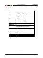
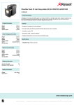
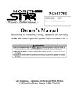
Service Manual
RL4000D2
First Edition
First Printing
Part No. 116473
September 2008
September 2008
Introduction
Important
Serial Number Information
Read, understand and obey the safety rules and
operating instructions in the appropriate Operator's
Manual on your machine before attempting any
maintenance procedure.
TEREX Corporation offers the following manuals
for these models:
Basic mechanical, hydraulic and electrical
skills are required to perform most procedures.
However, several procedures require specialized
skills, tools, lifting equipment and a suitable
workshop. In these instances, we strongly
recommend that maintenance and repair be
performed at an authorized TEREX dealer
service center.
TEREX RL4000 Operator's Manual .................... 116417
First Edition
Title
Part No.
TEREX RL4000 Service Manual ........................ 116473
First Edition
TEREX RL4000 Part's Manual ........................... 116444
First Edition
Leroy Somer Manual ........................................... 116118
Kubota Engine Manual ....................................... 893020
Technical Publications
Axis Manual ........................................................ 116117
TEREX Corporation has endeavored to deliver the
highest degree of accuracy possible. However,
continuous improvement of our products is a
TEREX policy. Therefore, product specifications
are subject to change without notice.
Marathon Manual ................................................ 116188
Readers are encouraged to notify TEREX of errors
and send in suggestions for improvement. All
communications will be carefully considered for
future printings of this and all other manuals.
Contact Us:
Copyright © 2008 by TEREX Corporation
www.TEREX.com
116473 Rev A September 2008
First Edition, Second Printing
"TEREX" is a registered trademark of TEREX
Corporation in the USA and many other countries.
"Super Quiet" is a trademark of TEREX
Corporation.
Printed on recycled paper
Printed in U.S.A.
ii
RL4000 Light Tower
Part No. 116473
September 2008
How to Read Your Serial Number
Serial Number Legend
The serial number plate on your RL4000 is located
on the cabinet next to the light tower mast.
Part No. 116473
RL4000 Light Tower
iii
September 2008
This page intentionally left blank.
iv
RL4000 Light Tower
Part No. 116473
September 2008
Section 1 • Safety Rules
Safety Rules
Danger
Failure to obey the instructions and safety rules
in this manual and the appropriate Operator's
Manual on your machine will result in death or
serious injury.
Many of the hazards identified in the
operator’s manual are also safety hazards
when maintenance and repair procedures
are performed.
Do Not Perform Maintenance
Unless:
You are trained and qualified to perform
maintenance on this machine.
You read, understand and obey:
- manufacturer’s instructions and safety rules
- employer’s safety rules and worksite
regulations
- applicable governmental regulations
You have the appropriate tools, lifting
equipment and a suitable workshop.
Part No. 116473
RL4000 Light Tower
v
Section 1 • Safety Rules
SAFETY RULES
September 2008
REV A
Be sure to wear protective eye wear and
other protective clothing if the situation
warrants it.
Personal Safety
Any person working on or around a machine must
be aware of all known safety hazards. Personal
safety and the continued safe operation of the
machine should be your top priority.
Read each procedure thoroughly. This
manual and the decals on the machine,
use signal words to identify the following:
Safety alert symbol—used to alert
personnel to potential personal
injury hazards. Obey all safety
messages that follow this symbol
to avoid possible injury or death.
Red—used to indicate the
presence of an imminently
hazardous situation which, if not
avoided, will result in death or
serious injury.
Orange—used to indicate the
presence of a potentially
hazardous situation which, if not
avoided, could result in death or
serious injury.
Yellow with safety alert symbol—
used to indicate the presence of a
potentially hazardous situation
which, if not avoided, may cause
minor or moderate injury.
Yellow without safety alert
symbol—used to indicate the
presence of a potentially
hazardous situation which, if not
avoided, may result in property
damage.
Green—used to indicate operation
or maintenance information.
Be aware of potential crushing hazards
such as moving parts, free swinging or
unsecured components when lifting or
placing loads. Always wear approved steel-toed
shoes.
Workplace Safety
Be sure to keep sparks, flames and
lighted tobacco away from flammable and
combustible materials like battery gases
and engine fuels. Always have an approved fire
extinguisher within easy reach.
Be sure that all tools and working areas
are properly maintained and ready for
use. Keep work surfaces clean and free of
debris that could get into machine components and
cause damage.
Be sure that your workshop or work area
is properly ventilated and well lit.
Be sure any forklift, overhead crane or
other lifting or supporting device is fully
capable of supporting and stabilizing the
weight to be lifted. Use only chains or straps that
are in good condition and of ample capacity.
Be sure that fasteners intended for one
time use (i.e., cotter pins and self-locking
nuts) are not reused. These components
may fail if they are used a second time.
Be sure to properly dispose of old oil or
other fluids. Use an approved container.
Please be environmentally safe .
vi
RL4000 Light Tower
Part No. 116473
September 2008
Table of Contents
REV A
Introduction
Important Information - Introduction ................................................................... ii
How to Read Your Serial Number ..................................................................... iii
Parts Stocking List ............................................................................................ ix
How to Order Parts ........................................................................................... xi
Service Parts Fax Order Form ......................................................................... xii
Section 1
Safety Rules
General Safety Rules ........................................................................................ v
Section 2
Section 3
Rev
Specifications
A
Specifications .............................................................................................. 2 - 1
A
Specifications (Continued) ........................................................................... 2 - 2
A
Specifications (Continued) ........................................................................... 2 - 3
A
Torque Specifications .................................................................................. 2 - 4
Rev
Scheduled Maintenance Procedures
Introduction .................................................................................................. 3 - 1
Pre-delivery Preparation Report ................................................................... 3 - 2
A
Maintenance Schedules
Kubota Lubrication and Maintenance Service Intervals ................................ 3 - 3
Leroy Somer Generators Maintenance Schedule ........................................ 3 - 4
Marathon Generators Maintenance Schedule .............................................. 3 - 5
Section 4
Rev
Troubleshooting
Introduction .................................................................................................. 4 - 1
A
Part No. 116473
Troubleshooting Guide ................................................................................. 4 - 2
RL4000 Light Tower
vii
September 2008
TABLE OF CONTENTS
Section 5
viii
Rev
REV A
Schematics
A
Introduction .................................................................................................. 5 - 1
A
AC Light Tower Wiring ................................................................................. 5 - 2
A
Wire Harness, Control Box, European, DC .................................................. 5 - 3
A
DC Wiring, European, Kubota ...................................................................... 5 - 4
A
DC Wiring, Kubota ....................................................................................... 5 - 5
A
Wire Harness, Inside Control Box, DC ......................................................... 5 - 6
A
MH or HPS Light Fixture .............................................................................. 5 - 7
A
1000 MH Ballast .......................................................................................... 5 - 8
A
1000 HPS Ballast ......................................................................................... 5 - 9
RL4000 Light Tower
Part No. 116473
September 2008
Parts Stocking List
REV A
Required Parts
The following parts are required to perform
maintenance procedures as outlined in the
TEREX RL4000 Parts and Service Manuals.
Description
Part No.
Kubota Models
Oil Filter .............................................................. 866050
Air Filter .............................................................. 866127
Fuel Filter ........................................................... 839200
V-belt .................................................................. 839209
Part No. 116473
RL4000 Light Tower
ix
September 2008
REV A
This page intentionally left blank.
x
RL4000 Light Tower
Part No. 116473
September 2008
How To Order Parts
REV A
Please be prepared with the following information
when ordering replacement parts for your TEREX
product:
Machine model number
Machine serial number
Terex part number
Part description and quantity
Purchase order number
"Ship to" address
Desired method of shipment
Name and telephone number of the
authorized TEREX Distributor in your area
Genie Industries
18340 NE 76th Street
P.O. Box 97030
Redmond, WA 98073-9730
Telephone (877) 367-5606
Fax (888) 274-6192
genieindustries.com
Use the Service Parts Fax Order Form on the
next page and fax your order to our Parts
Department.
If you don't know the name of your authorized
distributor, or if your area is not currently serviced
by an authorized distributor, please call TEREX
Corporation.
Machine Information
Model
Serial Number
Date of Purchase
Authorized TEREX Distributor
Phone Number
Part No. 116473
RL4000 Light Tower
xi
September 2008
Service Parts fax Order Form
FAX TO: (888) 274-6192 OR TOLL FREE: 877-367-5606
Please fill out completely
_________________________________
Account Number _______________________________
Your Name ______________________________
Your Fax Number _____________________________
_________________________________
Your Phone Number ____________________________
_________________________________
Ship To
Bill To
___________________________________
_________________________________
___________________________________
_________________________________
___________________________________
_________________________________
Purchase Order Number ____________________
___________________________________
Ship Via
___________________________________
Model(s) ______________________________________________________ Serial No.(s) _________________
Optional Equipment __________________________________________________________________________
Description
Quantity
Price
remove this page and make copies
Part Number
remove this page and make copies
Date
All backordered parts will be shipped when available via the same ship method as the original order
unless noted below:
o
Ship complete order only - no backorders
o
Ship all available parts and contact customer on disposition of backordered parts
o
Other (please specify)
FOR TEREX USE ONLY
Order Number ______________
Origin Code ________________
RL4000 Light Tower
Comments _________________________
Date Scheduled ____________
Ship Condition ______________
__________________________________
Order Total ________________
Terms Code ________________
__________________________________
Part No. 116473
September 2008
Section 2 • Specifications
Specifications
REV A
MAST
MAST ELEVATION
TOWER ROTATION
TOWER ROTATION
MAX WIND RATING
30' / 9.14M
359 DEGREES
MANUAL
62MPH / 100KPH
DIMENSIONS
SEE CHART ON PAGE 2-3
ENGINES
STANDARD
GENERATORS
STANDARD
OR
KUBOTA, D1105
DIESEL, 13.6 HP
MARATHON, 6 KW
201CSA5411, 60HZ
LEROY SOMER
36M6, 6KW, 60HZ
STANDARD
RECEPTACLES
QTY. 1, 120V, 20A, GFI, DUPLEX
QTY. 1, 240V, 30A, TWISTLOCK
STANDARD
BREAKERS
QTY. 4, 1P, 15A, LAMPS
QTY. 1, 2P, 30A, MAIN
QTY. 1, MINI, 1P, 20A, GFI RECEPTACLE
STANDARD
LAMPS
SEPARATELY SWITCHED
QTY. 4, 1000 WATT
METAL HALIDE, ROUND
Part No. 116473
RL4000 Light Tower
2-1
Section 2 • Specifications
September 2008
SPECIFICATIONS
REV A
TRAILER
WHEELS 13 X 4.5, 5 HOLE
TIRES, ST175/80D13, LOAD B
COLD PRESSURE, 35PSI / 250KPA
AXLE RATING 2000LBS
MAX TOW SPEED, 60MPH / 96KPH
NO BRAKES, STANDARD
TWO OUTRIGGERS, STANDARD
FUEL TANK
FUEL TYPE, NO.2 DIESEL ONLY
CAPACITY, 30 GALLONS / 114L
MATERIAL, POLYETHELENE
FUEL
CONSUMPTION
KUBOTA, .787 G/HR - 2.97L/HR
KUBOTA, RUN TIME, 30 GAL.= 38.3 HRS.
WEIGHT
6KW, TOTAL WEIGHT, NO FUEL, 1,725LBS. / 783KG
6KW, TOTAL WEIGHT, TANK FULL, 1,935LBS. / 878KG
TONGUE WEIGHT
6KW, 30 GALLON, 199LBS / 91KG
WITH FUEL
BATTERY
WET, 12V, GROUP 24, 460 CCA, STD-DUTY, LEAD ACID
2-2
RL4000 Light Tower
Part No. 116473
September 2008
Section 2 • Specifications
REV A
Part No. 116473
SPECIFICATIONS
RL4000 Light Tower
2-3
Section 2 • Specifications
September 2008
SPECIFICATIONS
REV A
SAE FASTENER TORQUE CHART
• This chart is to be used as a guide only unless noted elsewhere in this manual •
SIZE
Grade 5
THREAD
LUBED
20
28
1/4
5/16
3/8
7/16
1/2
9/16
5/8
3/4
7/8
1
1.125
1.25
1.5
LUBED
DRY
DRY
in- lbs
Nm
in- lbs
Nm
in- lbs
Nm
in- lbs
Nm
in- lbs
Nm
100
90
11.3
10.1
80
120
9
13.5
140
120
15.8
13.5
110
160
12.4
18
130
140
14.7
15.8
LUBED
18
24
16
24
14
20
13
20
12
18
11
18
10
16
9
14
8
12
7
12
7
12
6
12
A574 High Strength
Black Oxide Bolts
LUBED
Grade 8
DRY
LUBED
DRY
LUBED
f t - lbs
Nm
f t - lbs
Nm
f t - lbs
Nm
f t - lbs
Nm
f t - lbs
Nm
13
14
23
26
37
41
57
64
80
90
110
130
200
220
320
350
480
530
590
670
840
930
1460
1640
17.6
19
31.2
35.2
50.1
55.5
77.3
86.7
108.4
122
149
176
271
298
433
474
650
718
800
908
1138
1260
1979
2223
17
19
31
35
49
55
75
85
110
120
150
170
270
300
430
470
640
710
790
890
1120
1240
1950
2190
23
25.7
42
47.4
66.4
74.5
101.6
115
149
162
203
230
366
406
583
637
867
962
1071
1206
1518
1681
2643
2969
18
20
33
37
50
60
80
90
120
130
160
180
280
310
450
500
680
750
970
1080
1360
1510
2370
2670
24
27.1
44.7
50.1
67.8
81.3
108.4
122
162
176
217
244
379
420
610
678
922
1016
1315
1464
1844
2047
3213
3620
25
27
44
49
70
80
110
120
150
170
210
240
380
420
610
670
910
990
1290
1440
1820
2010
3160
3560
33.9
36.6
59.6
66.4
94.7
108.4
149
162
203
230
284
325
515
569
827
908
1233
1342
1749
1952
2467
2725
4284
4826
21
24
38
43
61
68
93
105
130
140
180
200
320
350
510
560
770
840
1090
1220
1530
1700
2670
3000
28.4
32.5
51.5
58.3
82.7
92.1
126
142
176
189
244
271
433
474
691
759
1044
1139
1477
1654
2074
2304
3620
4067
METRIC FASTENER TORQUE CHART
• This chart is to be used as a guide only unless noted elsewhere in this manual •
Class 4.6
Size
(m m )
5
6
7
LUBED
2-4
DRY
LUBED
Class 10.9
8.8
DRY
LUBED
Class 12.9
10.9
DRY
LUBED
12.9
DRY
in- lbs
Nm
in- lbs
Nm
in- lbs
Nm
in- lbs
Nm
in- lbs
Nm
in- lbs
Nm
in- lbs
Nm
in- lbs
Nm
16
19
45
1.8
3.05
5.12
21
36
60
2.4
4.07
6.83
41
69
116
4.63
7.87
13.2
54
93
155
6.18
10.5
17.6
58
100
167
6.63
11.3
18.9
78
132
223
8.84
15
25.2
68
116
1.95
7.75
13.2
22.1
91
155
260
10.3
17.6
29.4
LUBED
8
10
12
14
16
18
20
22
24
Class 8.8
4.6
DRY
LUBED
DRY
LUBED
DRY
LUBED
DRY
f t - lbs
Nm
f t - lbs
Nm
f t - lbs
Nm
f t - lbs
Nm
f t - lbs
Nm
f t - lbs
Nm
f t - lbs
Nm
f t - lbs
Nm
5.4
10.8
18.9
30.1
46.9
64.5
91
124
157
7.41
14.7
25.6
40.8
63.6
87.5
124
169
214
7.2
14.4
25.1
40
62.5
86.2
121
166
210
9.88
19.6
34.1
54.3
84.8
117
165
225
285
14
27.9
48.6
77.4
125
171
243
331
420
19.1
37.8
66
105
170
233
330
450
570
18.8
37.2
64.9
103
166
229
325
442
562
25.5
50.5
88
140
226
311
441
600
762
20.1
39.9
69.7
110
173
238
337
458
583
27.3
54.1
94.5
150
235
323
458
622
791
26.9
53.2
92.2
147
230
317
450
612
778
36.5
72.2
125
200
313
430
610
830
1055
23.6
46.7
81
129
202
278
394
536
682
32
63.3
110
175
274
377
535
727
925
31.4
62.3
108
172
269
371
525
715
909
42.6
84.4
147
234
365
503
713
970
1233
RL4000 Light Tower
Part No. 116473
September 2008
REV A
Section 3 • Scheduled Maintenance Procedures
Scheduled Maintenance Procedures
About This Section
This section contains detailed procedures for each
scheduled maintenance inspection.
Each procedure includes a description, safety
warnings and step-by-step instructions.
Observe and Obey:
Symbols Legend
Safety alert symbol—used to alert
personnel to potential personal
injury hazards. Obey all safety
messages that follow this symbol
to avoid possible injury or death.
Maintenance inspections shall be completed by
a person trained and qualified on the
maintenance of this machine.
Scheduled maintenance inspections shall be
completed as specified using the supplied
Lubrication and Maintenance Service Interval
Charts provided in this section.
Red—used to indicate the
presence of an imminently
hazardous situation which, if not
avoided, will result in death or
serious injury.
Failure to perform each procedure
as presented and scheduled could
result in death, serious injury or
substantial damage.
Orange—used to indicate the
presence of a potentially
hazardous situation which, if not
avoided, could result in death or
serious injury.
Immediately tag and remove from service a
damaged or malfunctioning machine.
Repair any machine damage or malfunction
before operating the machine.
Yellow with safety alert symbol—
used to indicate the presence of a
potentially hazardous situation
which, if not avoided, may cause
minor or moderate injury.
Keep records on all inspections for three years.
Machines that have been out of service for a
period longer than 3 months must complete the
quarterly inspection.
Yellow without safety alert
symbol—used to indicate the
presence of a potentially
hazardous situation which, if not
avoided, may result in property
damage.
Unless otherwise specified, perform each
maintenance procedure with the machine in the
following configuration:
· Machine parked on a firm, level surface
· Toggle switch in the "OFF" position
Green—used to indicate operation
or maintenance information.
· Wheels chocked
Indicates that a specific result is expected after
performing a series of steps.
Indicates that an incorrect result has occurred
after performing a series of steps.
Part No. 116473
RL4000 Light Tower
3-1
Pre-Deliver
Pre-Deliveryy Preparation
Fundamentals
Instructions
It is the responsibility of the dealer to perform the
Pre-delivery Preparation.
Use the operator’s manual on your machine.
The Pre-delivery Preparation is performed prior to each
delivery. The inspection is designed to discover if anything
is apparently wrong with a machine before it is put into
service.
A damaged or modified machine must never be used. If
damage or any variation from factory delivered condition is
discovered, the machine must be tagged and removed
from service.
Repairs to the machine may only be made by a qualified
service technician, according to the manufacturer's
specifications.
Scheduled maintenance inspections shall be performed by
qualified service technicians, according to the
manufacturer's specifications and the requirements listed
in the responsibilities manual.
The Pre-delivery Preparation consists of completing the
Pre-operation Inspection, the Maintenance items and the
Function Tests.
Use this form to record the results. Place a check in the
appropriate box after each part is completed. Follow the
instructions in the operator’s manual.
If any inspection receives an N, remove the machine from
service, repair and re-inspect it. After repair, place a check
in the R box.
Legend
Y = yes, completed
N = no, unable to complete
R = repaired
Comments
Pre-Delivery Preparation
Pre-operation inspection completed
Maintenance items completed
Function tests completed
Model
Serial number
Date
Machine owner
Inspected by (print)
Inspector signature
Inspector title
Inspector company
TEREX Rock Hill
P.O. BOX 3147
Rock Hill, SC 29732 USA
Toll Free (800) 433-3026 in U.S.A. and Canada
Copyright © 2006 by TEREX Corporation. TEREX® is a registered trademark of TEREX
Corporation.
Rev B
Y
N
R
September 2008
Section 3 • Scheduled Maintenance Procedures
Maintenance Schedules
REV A
Kubota Lubrication and Maintenance Service Intervals
ITEM
Check of fuel pipes and clamp bands
Check engine oil and coolant level
Cleaning of air cleaner element
Check of battery electrolyte level
Check of fan belt tightness
Check of radiator hoses and clamp
bands
Check of intake air line
Replacement of oil filter cartridge
Replacement of fuel filter cartridge
Removal of sediment in fuel tank
Every 50
Hours
Every
100
Hours
Every
200
Hours
Every
400
Hours
Every
500
Hours
Every
Year
Every
800
Hours
Every
1500
Hours
Every
3000
Hours
Every
Two
Years
•
•
•
•
•
•
•
•
•
•
Cleaning of water jacket (radiator
interior)
•
•
Replacement of fan belt
•
Replacement of air cleaner element
Check of damage in electric wiring
and loose connections
•
•
Check of valve clearance
Check of fuel injection nozzle injection
pressure
•
•
•
•
Check of turbo charger
Check of injection pump
Check of injection timer
Replacement of battery
•
•
Replacement of radiator hoses and
clamp bands
•
Change of radiator coolant (L.L.C.)
Replacement of fuel pipes and clamp
bands
•
•
Replacement of intake air line
*Refer to the manufacturer's manuals for detailed maintence intervals and instructions. If the
information in the manufacturer's manual differs from that in this manual the manufacturer's manual
should take precedence.
Part No. 116473
RL4000 Light Tower
3-3
Section 3 • Scheduled Maintenance Procedures
September 2008
MAINTENANCE SCHEDULES CONTINUED
REV A
Leroy Somer Generators Maintenance Schedule
ITEM
DAILY
Inspect and verify operator reports
Visual inspection of generator housing and air
inlet/outlets
Visually inspect installation for sign of particulate
or liquid contaminant instrusion.
Check control panel voltmeter for proper stability
and voltage output. Monitor the power factor and
generator loading during operation.
Visually inspect the generator non-drive end
bearing exterior for dirt, and clean if necessary.
If installed, inspect any generator air filters for
build up of contaminants, and clean or replace as
required.
Visually inspect the stator output leads and
insulation for cracking or damage.
Check all exposed electrical connections for
tightness.
Check transformers, fuses, capacitors, and
lightning arrestors for loose or physical damage.
Weekly
2000 Hours 8000 Hours 20000 Hours 30000 Hours
or 6 Months or 1 Year
or 3 Years or 5 Years
•
•
•
•
•
•
Check all lead wires and electrical connections for
proper clearance and spacing.
Clean the inside of the outlet box, air screens and
air baffles with compressed air or electrical
solvent if needed.
Check machine vibrations and bearing condition
against those established and recorded during
original commissioning period or as defined by
OEM.
Check IR (insulation resistance) to ground on all
generator windings, including the main rotating
assembly, the main stator assembly, the exciter
field and armature assemblies, and any optional
PMG assembly - record
Remove the end brackets and visually inspect the
generator end windings for oil or dirt
contamination. Excessive contamination may
necessitate surface cleaning*.
Disassemble the generator (this includes rotor
removal).
•
•
•
•
•
•
•
•
•
•
•
Clean the generator windings.
Replace the bearings
*Refer to the manufacturer's manuals for detailed maintence intervals and instructions. If the
information in the manufacturer's manual differs from that in this manual the manufacturer's manual
should take precedence.
3-4
RL4000 Light Tower
Part No. 116473
September 2008
Section 3 • Scheduled Maintenance Procedures
MAINTENANCE SCHEDULES CONTINUED
REV A
Marathon Generators Maintenance Schedule
ITEM
DAILY
200 Hours
10000
Hours
•
Visual inspection
Clean and inspect after every 200 hours of
normal operating time. If generator is housed
in a harsh environment, it is advisable to clean
and inpect the unit more frequently.
•
•
Replace the bearing
*Refer to the manufacturer's manuals for detailed maintence intervals and instructions. If the
information in the manufacturer's manual differs from that in this manual the manufacturer's manual
should take precedence.
Part No. 116473
RL4000 Light Tower
3-5
Section 3 • Scheduled Maintenance Procedures
September 2008
RL4000 Light Tower
Part No. 116473
This page intentionally left blank.
3-6
September 2008
Section 4 • Troubleshooting
Troubleshooting
REV A
Before Troubleshooting:
Read, understand and obey the safety rules
and operating instructions in the appropriate
operator's manual on your machine.
Be sure that all necessary tools and test
equipment are available and ready for use.
Observe and Obey:
Troubleshooting and repair procedures shall be
completed by a person trained and qualified on
the repair of this machine.
Be aware of the following hazards and follow
generally accepted safe workshop practices.
Immediately tag and remove from service a
damaged or malfunctioning machine.
Repair any machine damage or malfunction
before operating the machine.
Unless otherwise specified, perform each
repair procedure with the machine in the
following configuration:
· Machine parked on a firm, level surface.
· Wheels chocked.
· Toggle switch in "OFF" position.
Electrocution hazard. Exposure to
electrically charged circuits could
result in death or serious injury.
Remove all rings, watches and
other jewelry.
Electrocution hazard. Attempting
to sevice the machine before the
capacitors are fully discharged will
result in death or serious injury.
High voltage. Exposure to
electrical wires or electrical current
will result in death or serious
injury. Remove all rings, watches
and other jewelry. Turn off all
power when not needed for
testing. Use extreme caution when
working with high voltage electrical
components.
Burn hazard. Contact with hot
engine components may cause
severe burns. Use caution when
working around a hot engine.
Part No. 116473
RL4000 Light Tower
4-1
Section 4 • Troubleshooting
September 2008
REV A
Troubleshooting Guide
The engine/generator set is tested and set at the factory for proper operation in the field. These units
should never require additional adjustments in the field. If needed, adjustments should only be made by a
qualified service technician, otherwise the manufacturer’s warranty may become void.
TROUBLE
1.Boom will not rise to
the operating position.
POSSIBLE CAUSE
a.Yoke pin is in place
b.Defective cable
or pulley
c.Defective winch
2.Boom will not telescope.
a.Defective winch
b.Broken cable or pulley
3.Engine will not turn over
a.Dead battery
b.Engine has seized due to loss
of fluids
4.Engine turns over but will
not start
a.Empty fuel tank
b.Clogged fuel lines or filter
5.Engine runs rough
c.Leaking fuel lines or a loss
of prime
d.Heater elements burned out
e.Fuel line solenoid is not open
a.Clogged or leaking fuel system
b.Clogged exhaust system
c.Clogged air filter
d.Clogged or stuck fuel injectors
e.Valve clearances are out of
adjustment or the valve spring
may be damaged
f.Defective governor or fuel pump
4-2
RL4000 Light Tower
REMEDY
a.Remove yoke pin
b.Have a trained
mechanic examine and
repair as needed
c.Have a trained
mechanic examine
and replace as needed
a.Have a trained
mechanic examine
and replace as needed
b.Have a trained
mechanic examine
and replace as needed
a.Check the battery voltage or
loose cables
b.Have a trained
mechanic examine and
repair as needed
a.Fill tank with #2 diesel fuel
b.Check and clean the fuel
system as needed
c.Replace any leaking fuel lines
and tighten connections
d.Replace heater elements
e.Replace fuel line solenoid
a.Replace fuel lines, tighten all
connections, inspect the pickup
tube and inspect the fuel filter
b.Clear the exhaust system
c.Clear air filter
d.Have a trained
mechanic examine
e.Have a trained
mechanic examine
f.Have a trained
mechanic examine
Part No. 116473
September 2008
Section 4 • Troubleshooting
TROUBLESHOOTING
REV A
TROUBLE
POSSIBLE CAUSE
6.Engine runs but produces a
dense smoke
a.Crankcase oil level is too high
b.Low compression
7.Engine overheats
c. Clogged air cleaner
a.Blocked cooling air intakes
b.Low coolant levels
8.Engine runs but the battery
voltage is low
9.Engine runs but the lights will
not operate
c.Radiator fins have become
clogged
d.Fan belt is loose
a.Alternator has failed
a.Circuit breakers are tripped
b.Loose connections in the wiring
system
c.Burned out bulb
d.Defective capacitor
(Leroy Somers Generator)
e.Defective AC generator
f.Engine speed is too low
g.Defective ballast and capacitors
10.Unusual noise coming from
the generator
11.Lamp will not start
a.The generator has a defective
bearing or damaged fan blade
a.Lamp loose in socket
b.Floodlight plugs not tight
c.Defective ballast
d.Low voltage
Part No. 116473
RL4000 Light Tower
REMEDY
a.Drain oil to its proper level
b.Have a trained mechanic
inspect for broken or seized
rings. Inspect valve clearances
c. Replace air cleaner element
a.Inspect the front and rear intakes
and clear as needed
b.Replace the coolant with a 50%
water/coolant solution
c.Clear the radiator fins
d.Tighten fan belt
a.Have a trained mechanic inspect
the alternator
a.Reset the circuit breaker
b.Have a trained electrician inspect
the ballast box wiring system
c.Replace the bulbs as needed
d.Have a trained electrician inspect
the capacitor
e.Have a trained electrician inspect
the generator
f.Have a trained mechanic inspect
the engine speed and reset to
1800rpm @ 60hz
g.Have a trained electrician inspect
the ballast and capacitors
a.Have a trained electrician inspect
the generator
a.Inspect lamp base to see if there
is arcing at center contact button.
Tighten lamp. Check socket for
damage. Replace if needed.
b.Check plug and receptacle. Tighten
if needed. Make sure power is off.
c.Interchange ballast plugs. If lamp
starts, replace ballast. Check for
swollen capacitors, charred wiring,
core and coil, or other signs of
excessive heat.
d.Check line voltage at ballast input.
Voltage should be within 10% of
rating when operating at normal load.
Increase supply voltage or remove
external load.
4-3
Section 4 • Troubleshooting
September 2008
TROUBLESHOOTING
TROUBLE
11.Lamp will not start
12.Lamp starts slowly (arc does
not strike when switch is first
turned on
13.Circuit breaker trips on lamp
startup
14.Lamp light output low
REV A
POSSIBLE CAUSE
e.Improper ballast
f.Lamp has been operating; cool
down time insufficient
a.Defective lamp
a.Short circuit or ground
a.Normal lamp depreciation
b.Dirty lamp or fixture
c.Defective ballast
d.Wrong voltage
e.Improper ballast
15.Lamp colors different
a.Normal lamp depreciation
b.Dirty lamp or fixture
c.Wrong lamp
16.Arc tube discolored or swollen
a.Over voltage from power supply
b.Improper ballast
17.Short lamp life
a.Lamp damaged
b.Improper ballast
18.Lamp flickers or goes outintermittent or cycling
a.Improper Ballast
b.New lamp
4-4
RL4000 Light Tower
REMEDY
e.The ballast name plate data should
agree with the line voltage and lamp
used. If not, replace the ballast.
f.Switch off breaker and allow lamp
to cool.
a.Lamp may glow for an extended
period of time. Replace after
checking voltage and ballast
a.Check wiring against diagram.
inspect for shorts or ground. Fix as
needed.
a.Replace lamp
b.Clean lamp and fixture
c.Interchange ballast plugs. If lamp
starts, replace ballast. Check for
swollen capacitors, charred wiring,
core and coil, or other signs of
excessive heat.
d.Check line voltage at ballast input.
Voltage should be within 10% of
rating when operating at normal load.
Check wiring connections for voltage
loss. Check socket contact point.
e.Check ballast name plate against
lamp data
a.Replace lamp
b.Clean lamp and fixture
c.Check data on lamps and replace
as needed.
a.Check voltage at ballast, for current
or voltage surges, for shorted
capacitors and replace as needed
b.Check ballast name plate against
lamp data
a.Check for outer bulb cracks,
cracks where lamp meets base, and
for broken arc tube or loose metal
parts. Replace as needed.
b.Check ballast name plate against
lamp data
a.Check ballast name plate against
lamp data
b.Under certain conditions new lamps
may "cycle". Usually after 3 tries to
start at 30 to 60 second intervals,
lamp will stabilize and operate normal
Part No. 116473
September 2008
Section 4 • Troubleshooting
TROUBLESHOOTING
REV A
TROUBLE
18.Lamp flickers or goes outintermittent or cycling
POSSIBLE CAUSE
c.Defective lamp
d.High spike ballast
REMEDY
c.Replace lamp
d.Ballast produces high spike current.
Measure with oscilloscope. Replace
ballast as required.
IF YOU FEEL AN ELECTRIC SHOCK AT ANY TIME WHILE OPERATING THIS UNIT, SHUT IT DOWN
IMMEDIATELY! HAVE THE UNIT INSPECTED BY A TRAINED ELECTRICIAN.
THIS ENGINE/GENERATOR SET IS FACTORY INSTALLED, TESTED, AND SET FOR FIELD
OPERATION. ANY DAMAGE TO THE ENGINE OR GENERATOR UNITS OCCURRING AFTER
ADJUSTMENTS ARE MADE IN THE FIELD BY UNAUTHORIZED PERSONNEL WILL NOT BE
COVERED BY YOUR MANUFACTURER’S WARRANTY AND WILL ALSO VOID THE
MANUFACTURER’S WARRANTY ON THIS PARTICULAR UNIT. IF YOU CAN NOT REACH YOUR
LOCAL DEALER, CONTACT THE FACTORY SERVICE MANAGER TOLL FREE AT 1-800-433-3026.
Light Fixture Troubleshooting
DO NOT OPEN FIXTURE WHILE LIGHT
CIRCUIT BREAKER IS “ON”. ALLOW
LAMP TO COOL BEFORE TOUCHING.
**TAKE EXTRA PRECAUTIONS WHEN
TROUBLESHOOTING ELECTRICAL PROBLEMS**
A. Only use a voltmeter with two well-insulated pin probes rated for 600 volts.
B. Treat all conductors as potentially hot.
C. Proceed through circuits systematically,
operating only one section at a time.
D. Before disconnecting ballast, turn off circuit
breaker and wait 30 seconds for capacitor
to discharge.
E. If all the lights are out and all the ballasts
are receiving power, suspect burned out
power cable.
Part No. 116473
RL4000 Light Tower
4-5
Section 4 • Troubleshooting
September 2008
RL4000 Light Tower
Part No. 116473
This page intentionally left blank.
4-6
September 2008
Section 5 • Schematics
Schematics
REV A
About This Section
There are two groups of schematics in this section.
An illustration legend precedes each group of
drawings.
Electrical Schematics
Observe and Obey:
Electrocution hazard. Contact with
electrically charged circuits could
result in death or serious injury.
Remove all rings, watches and
other jewelry.
Troubleshooting and repair procedures shall be
completed by a person trained and qualified on
the repair of this machine.
Immediately tag and remove from service a
damaged or malfunctioning machine.
Repair any machine damage or malfunction
before operating the machine.
Before Troubleshooting:
General Repair Process
Malfunction
discovered
Read, understand and obey the safety rules
and operating instructions in the appropriate
operator's manual on your machine.
Be sure that all necessary tools and test
equipment are available and ready for use.
Part No. 116473
Identify
symptoms
Troubleshoot
problem
still exists
Return to
service
RL4000 Light Tower
problem
solved
Inspect
and test
Perform
repair
5-1
Section 5 • Schematics
September 2008
AC Light Tower Wiring
Drawing #6495
5-2
REV A
RL4000 Light Tower
Part No. 116473
September 2008
Section 5 • Schematics
Wire Harness, Control Box, European, DC
Drawing #116810
REV A
Part No. 116473
RL4000 Light Tower
5-3
Section 5 • Schematics
September 2008
DC Wiring, European, Kubota
Drawing #116813
5-4
REV A
RL4000 Light Tower
Part No. 116473
September 2008
Section 5 • Schematics
DC Wiring, Kubota
Drawing #116814
REV A
Part No. 116473
RL4000 Light Tower
5-5
Section 5 • Schematics
September 2008
Wire Harness, Inside Control Box, DC
Drawing #116815
5-6
REV A
RL4000 Light Tower
Part No. 116473
September 2008
Section 5 • Schematics
MH or HPS Light Fixture
Drawing #2985A
REV A
Part No. 116473
RL4000 Light Tower
5-7
Section 5 • Schematics
September 2008
1000 MH Ballast
Drawing #2986
5-8
REV A
RL4000 Light Tower
Part No. 116473
September 2008
Section 5 • Schematics
1000 HPS Ballast
Drawing #2987
REV A
Part No. 116473
RL4000 Light Tower
5-9
California Proposition 65
Warning
The exhaust from this product
contains chemicals known to
the State of California to
cause cancer, birth defects
or other reproductive harm.
Towing Checklist
(Use at each stop)
Before Towing
· Boom hold-down latch is securely locked in place
· Towing hitch is properly secured to tow vehicle
· Safety chains (if required) are properly attached
and secure (chains are crossed below hitch)
· All lights are connected and working
· Tires are properly inflated
Before Driving
· Fasten safety restraints
· Properly adjust mirrors
On The Road
· Do not exceed 60 mph / 97 km/h. Obey all local
and national towing speed laws
· Check connections and tire pressure at each stop
· Slow down for hazardous conditions
· Allow extra distance for following and passing other
vehicles
Genie North America
Phone 425.881.1800
Toll Free USA and Canada
800.536.1800
Fax 425.883.3475
Genie Australia Pty Ltd.
Phone +61 7 3375 1660
Fax +61 7 3375 1002
Phone +86 21 53852570
Fax +86 21 53852569
Genie Malaysia
Phone +65 98 480 775
Fax +65 67 533 544
Genie Japan
Phone +81 3 3453 6082
Fax +81 3 3453 6083
Genie Korea
Phone +82 25 587 267
Fax +82 25 583 910
Genie Brasil
Phone +55 11 41 665 755
Fax +55 11 41 665 754
Genie Holland
Phone +31 183 581 102
Fax +31 183 581 566
Genie Scandinavia
Phone +46 31 575100
Fax +46 31 579020
Genie France
Phone +33 (0)2 37 26 09 99
Fax +33 (0)2 37 26 09 98
Genie Iberica
Phone +34 93 579 5042
Fax +34 93 579 5059
Genie Germany
Phone +49 (0)4202 88520
Fax +49 (0)4202 8852-20
Genie U.K.
Phone +44 (0)1476 584333
Fax +44 (0)1476 584334
Genie Mexico City
Phone +52 55 5666 5242
Fax +52 55 5666 3241
Distributed By:
Genie China