1
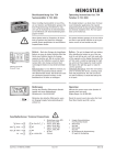
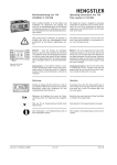
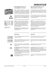
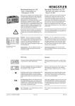
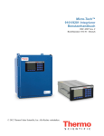
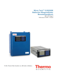
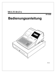
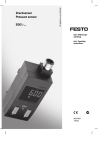
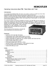
Lithium 3V, CR 1/2 AA
25 mm, Ø 15 mm
Sach-Nr. 2 734 001 Rev. 010698
Betriebsanleitung tico 734
Differenzzähler 0 734 001
Operating instructions tico 734
Differential totaliser 0 734 001
Dieser 8-stellige Differenzzähler ist für das Überwachen von Summen, Stückzahlen, Längen oder Mengen
geeignet. Zwei Eingänge erlauben echte Differenzzählung. Skalierfaktor, Dezimalpunkt und Offsetwert
ermöglichen die Anzeige in aussagekräftigen Einheiten.
This 8-digit differential totaliser is an ideal choice for
advanced count totalisation applications. The dual
input channels enable true add/subtract counting.
Input calibrator, decimal point and offset value setting
allow the input pulses to be displayed as meaningful
engineering units.
Dieses Symbol steht bei Textstellen, die besonders zu
beachten sind, damit der ordnungsgemäße Einsatz gewährleistet ist und Gefahren ausgeschlossen werden.
This symbol inidcates passages in the text where you
have to pay special attention so as to guarantee correct use and exclude any risk.
Batterie - Nach dem Einlegen der beigefügten Batterie in einen der beiden Schächte führt das Gerät
einen Selbsttest durch; alle Anzeigesegmente leuchten
auf. Mit der rechten Taste beenden Sie den Selbsttest,
worauf die Typennummer (1) in der Anzeige erscheint.
Nach nochmaligem Drücken ist das Gerät betriebsbereit.
Battery - The unit is shipped with one battery. After
installing the battery in one of the two slots the unit
will go into a self test mode with all the segments on
the display illuminated. The self test mode is exited by
depressing the right key, which will then display the
model number (1). Depress the right key again to ready
the unit for operation.
Batteriewechsel: 1.) neue Batterie einsetzen, 2.) verbrauchte herausnehmen (Gerät arbeitet ohne Datenverlust weiter). Das Gerät kann auch mit 2 Batterien
betrieben werden, um die Betriebszeit auf 10 Jahre zu
verlängern.
Exchanging the battery: insert the new battery prior to
removing the old one, retaining count total and program data. The unit can also be run with 2 batteries to
extend the battery life to 10 years.
Bedienung
Operation
Anzeige des aktuellen Zählerstandes (Anzahl Impulse
seit letztem Reset * Skalierfaktor). Der Zählerstand
ergibt sich aus (A-B)* Skalierfaktor.
Wertebereich: - 9 999 999 bis 99 999 999
Indicates the present count value (equals to the number of pulses received since the last reset multiplied by
the count input calibrator. The Count value results
form (A-B) multiplied by the count input calibrator.
Display range: -9 999 999 bis 99 999 999
Rücksetzen des Zählers (nur wenn die Tastenrückstellung durch die Programmierung freigegeben ist).
Resets the count value (only if Front Panel Reset is enabled by the programming).
Wird nur für die Programmierung benötigt (siehe
nächste Seite).
Only required for the programming (see next page).
Nach Änderungen in der Programmierung muß ein
Reset durchgeführt werden!
After changes in the programming you must reset the
counter!
Tico 734
Seite 1/4
Programmierung
Programming
Um in die Programmierung zu gelangen, müssen Sie
den Eingang Programmfreigabe mit 0 V verbinden.
Zum Beenden der Programmierung lösen Sie die
Verbindung wieder und verlassen mit der Taste H den
letzten Parameter.
Before you can start programming, connect the Program
Enble input to Gnd. To terminate programming
unconnect this input again and leave the last parameter
with the H key.
Programmierung einleiten, der erste Programmparameter wird angezeigt. Weiterschalten zum nächsten Programmparameter. Eine Ziffer blinkt:
Verändern der blinkenden Ziffer.
Enters programming mode and the first program parameter appears. Scroll to next program parameter. While
digit is flashing: edits the flashing digit.
Numerische Parameter: Jeweils nächste zu ändernde
Ziffer auswählen (Ziffer beginnt zu blinken). Es müssen alle Ziffern nach rechts durchlaufen werden, um
den Parameter zu beenden.
Übrigen Parameter: nächsten Auswahlpunkt wählen.
Numeric Parameters: Select next digit to be edited (digit
begins flashing). Starts wiht the leftmost digit. All digits
must be stepped through til the right to finish the parameter.
Other Parameters: select next menue item.
1.
01.0000
Skalierfaktor: Mulitipliziert die Eingangsimpulse mit
einem einstellbaren Wert von 0.0001 bis 99.9999 und
zeigt das Ergebnis an.
Count Input Calibrator: Multiplies the input pulses by a
value settable from 0.0001 to 99.9999, and displays the
result as the count value.
2.
off
Dezimalpunkt: Setzt den Dezimalpunkt in der
Anzeige. Wertebereich: kein (oFF) bis 0.00000. Die
Auswahl erfolgt mit “R”
Decimal Point: Sets the decimal point on the count display from off to 0.00000. The R-key is used to scroll
through the choices.
3.
000000
Setzwert: Rücksetzen des Zählers auf einen von 0
verschiedenen Wert im Bereich -999 999 bis 999 999.
Count Offset: Enables the counter to be reset to a value
other than 0. Settable in a range from 999999 to
999999.
Freigabe Tastenrückstellung: Bei (on) kann der Zähler,
zusätzlich zur externen Rückstellung, auch über die
R-Taste zurückgesetzt werden.
Front Panel Reset Enable: When active (on) the count
value can be reset with the R-key. If set to oFF, the total
value can only be reset with remote reset input.
4.
on
Anschlußschema / Terminal Connections
4
R eset
4
5
P rogr.
3
A:30 Hz
3
6
B:30 Hz
2
A:10kHz
2
7
B:10kHz
1
0V
1
8
10-28 VDC
Rückstellung extern, NPN
Remote Reset, NPN
Input A, 30 Hz, NPN
Input A, 30 Hz, NPN
Input A, 10 kHz, PNP
Input A, 10kHz, PNP
0V, Gnd
Common
5
6
7
8
Freigabe Tastenrückstellung
Front Panel Reset Enable
Input B, 30 Hz, NPN
Input B, 30 Hz, NPN
Input B, 10 kHz, PNP
Input B, 10 kHz, PNP
DC-Versorgung für Hinterleuchtung
DC supply for backlighting
Installationshinweise
Installation Notes
Um die EMV zu erreichen sind folgende Hinweise zu beachten:
Für die Signalleitungen sind geschirmte Leitungen zu verwenden. Die
Schirmung ist beidseitig an Erde zu legen, jedoch ohne Anbindung an
den Zähler.
Bei Anschluß einer externen Spannungsversorgung sind Hin und
Rückleitung nahe am Zähler zweimal durch den Ferrit mit der Sach-Nr.
3 560 037 zu schleifen.
In order to achieve the EMV please observe the following:
Use shielded cables for the signal input lines. Connect the shield at both
ends to earth ground but without connection to the unit.
Connecting an external power supply: lead both supply cables with two
turns through the ferrite, part no. 3 560 037, as they enter the counter.
Sach-Nr. 2 734 001 Rev. 010698
Tico 734
Seite 2/4
Technische Daten 0 734 001
Technical Data 0 734 001
Stromversorgung
Lithiumbatterie 3 V (CR 1/2 AA), typ. Lebensdauer 5
Jahre (10 Jahre bei 2 Batterien). "Lo BAT" blinkt in
Anzeige ca. 2 Wochen vor Ende der Betriebszeit.
Power Supply
Single or dual lithium 3 V battery (CR 1/2 AA), typical life time of 5 years (10 years with 2 batteries).
"Lo BAT" display flashes approx. 2 weeks prior to end
of battery life.
Anzeige
LCD, 12 mm hoch, Zähler 8-stellig. Gesamtes
Anzeigefeld hinterleuchtbar mittels 10-28 VDC an
Klemme (8), Stromaufnahme 21..34 mA
Display
LCD, 12 mm height, 8 digits. Whole display area can
be backlit with a 10-28 VDC supply, green-yellow
colour, backlight current 21..34 mA
High Speed
PNP, max. 10 kHz (Impuls/Pause 1:1), Low < 1.0 V,
Eingang (2), (7) High > 2.0 V, Impuls >45 µs, Impedanz 1 Mq, max.
28 VDC
High Speed
Inputs (2), (7)
PNP, max 10 kHz (50 % duty cycle), Low < 1.0 V,
High > 2.0 V, impulse > 45 µs, imped.ance 1 Mq,
max. 28 VDC
Low Speed
NPN, max. 30 Hz (Impuls/Pause 1:1),
Eingang (3), (6) 1.0 V, High > 2.0 V, Impedanz 1 Mq, max. 28 VDC
Low Speed
Input (3), (6)
NPN, max. 30 Hz (50 % duty cycle), Low < 1.0 V,
High > 2.0 V, impedance 1 Mq, max. 28 VDC
Freigabe
Eingang (5)
NPN, statisch, ermöglicht den Zugang zur
Programmierung mit der linken Taste, max. 28 VDC
Progr. Enable
Input (5)
NPN, level sensitive, allows access to programming with the left front key, max. 28 VDC
Reset
Eingang (4)
NPN, flankengetriggert, max. 30 Hz bei
Impuls/Pause 1:1, max. 28 VDC
Reset Input (4)
NPN, edge triggered, max. 30 Hz at 50 % duty cycle,
max. 28 VDC
Montage
Fronttafelmontage mit Spannrahmen
Mounting
Front panel mounting with mounting bracket
Abmessung
DIN 36 mm x 72 mm, Tiefe 36 mm, Breite inkl.
Spannrahmen 83 mm
Dimensions
DIN 36 x 72 mm, 36 mm total depth, total width 83
mm including mounting bracket
Fronttafel
33 +0,3 mm x 68+ 0,3 mm, Einbautiefe 29 mm
Fronttafelstärke max. 8 mm
Panel
33+0,3 mm x 68+0,3 mm, depth behind panel < 29 mm;
panel thicknes max. 8 mm
Schutzart
Frontseite IP 65
Rating
Front Panel IP 65
Temperatur
Betrieb:
Lagerung:
Temperature
Operating:
Storage:
EMV
Störaussendung: EN 50081-2 (‘93)
Störfestigkeit: EN 80052-2 (‘95)
EMC
Emission: EN 50081-2 (‘93)
Immunity: EN 50082-2 (‘95)
Allgemeine
Auslegung
EN 61010 Teil 1; Schutzklasse entsprechend II
Verschmutzungsgrad 2
Überspannungskategorie II
General
EN 61010 part 1; Protection according to class II
Contamination level 2
Overvoltage category II
0 °C bis +50 °C
-20 °C bis +60 °C
0 °C to +50 °C
-20 °C to +60 °C
Abmessungen/Dimensions
Maße in mm; Einbau-Ausschnitt: 33 x 68
units in mm; panel cutout 33 x 68
A: Dichtring, bitte auf korrekten Sitz achten
gasket, please secure proper fit
B: Spannrahmen mit Schrauben, Rastnasen deutlich einrasten
mounting bracket with screws, tabs must catch in the groves
Sach-Nr. 2 734 001 Rev. 010698
Tico 734
Seite 3/4
Sicherheitshinweise
Safety and warning hints
Der Anwendungsbereich der Produkte liegt in industriellen
Prozessen und Steuerungen, wobei die Überspannungen, denen
das Produkt an den Anschlußklemmen ausgesetzt wird, auf
Werte der Überspannungskategorie II begrenzt sein müssen.
I Dieses Gerät ist gemäß DIN EN 61010 Teil1 - Sicherheitsbestimmmungen für elektrische Meß-, Steuer-, Regel- und
Laborgeräte - gebaut und geprüft. Es hat das Werk in
sicherheitstechnisch einwandfreiem Zustand verlassen. Um
diesen Zustand zu erhalten und einen gefahrlosen Betrieb
sicherzustellen, muß der Anwender die Hinweise und Warnvermerke beachten, die in der Betriebsanleitung und diesem Merkblatt für Sicherheitshinweise enthalten sind!
I Einbau und Montage dürfen nur durch eine Elektrofachkraft erfolgen.
I Das Gerät darf nur in eingebautem Zustand betrieben werden.
I Bei Einbau und Montage der Geräte sind die Vorschriften
der öffentlichen EVU's zu beachten.
I Vor Inbetriebnahme ist sicherzustellen, daß die angeschlossenen Versorgungs- und Steuerleitungen den technischen
Daten entsprechen.
I Die Anschlußklemmen sind durch den Einbau zu schützen.
I Um die Handrückensicherheit der Anschlußklemmen einzuhalten, ist ein ordnungsgemäßer Anschluß der stromführenden Leiter an die Klemmen erforderlich.I Wenn ein
gefahrloser Betrieb nicht mehr möglich ist, so ist das Gerät
außer Betrieb zu setzen und gegen unabsichtigen Betrieb
zu sichern.
I Die Versorgung des Gerätes sollte aus einer SELV-Spannungsversorgung (siehe DIN EN 60950) erfolgen, da im
Gerät keine galvanische Trennung zwischen den elektronischen Anschlüssen besteht.
I Die Einbauumgebung und Verkabelung hat maßgeblichen
Einfluß auf die EMV (Störausendung und Störfestigkeit) des
Gerätes, so daß bei der Inbetriebnahme die EMV der gesamten Anlage (Gerät) sicherzustellen ist.
I Es dürfen nur gleichartige Stromkreise mit den Anschlußklemmen des Gerätes verbunden werden, SELV-Stromkreise
oder ELV-Stromkreise bei maximalem Anschlußquerschnitt
von 1,5 mm².
The range of applications for this product are industrial processes and controls, where the overvoltages applied to the product
at the connection terminals are limited to values of the overvoltage category II.
I This device is made and tested according to DIN EN 61010
Part 1 and has left the factory in a perfect safety state. To
keep this state and secure operation without danger, the
user has to observe the saftety and warning hints, contained in this manual.
I Assembling and mounting of electrical devices are restricted to be done by skilled electricians.
I Mount devices are only allowed to be operated when
mounted.
I Finger protection at connection part of mount devices is to
be secured when mounting.
I While mounting the device, it must be secured that the
requirements, which are asked for the device in the pertaining standards for safety, are not affected in a negative
way, so reducing the safety of this mount device.
I Mounting and assembling of the device needs observation
of the specifications of the local Energy Suppliers.
I Before switching on, make sure that the power and control
voltages are not exceeding the values in accordance with
the technical data.
I If it is to be assumed that operation without danger is not
further possible, the device must be put out of operation
and secured from unintentional operation.
I The device should be supplied from a SELV-Source (see DIN
EN 60950), because there is no galvanic separation of the
inputs within the device.
I The mounting environment and nearby cabling have an
important influence on the EMC (noise radiation and noise
immunity) of the device. When putting into operation, the
EMC of the whole installation (unit) has to be secured. In
particular, the relay outputs are to be protected from high
noise radiation by suitable wiring.
I Only circuits of the same type are allowed to be connected
to the terminals, SELV sources or ELV sources with 1,5 mm²
wiring.
© 1998 HENGSTLER GmbH
HENGSTLER GmbH claims the copyright for this documentation.
This documentation may not changed, amended, or copied without prior written consent of HENGSTLER GmbH, and may not be used in
contradiction to this companys rightful interests.
Technical data subject to alterations.
Hengstler GmbH
Postfach 11 51
D-78550 Aldingen/Germany
Hausanschrift: Uhlandstraße 49
D-78554 Aldingen
Phone +49-7424-89 0
Fax +49-7424-89 500
Member of the
Vertrieb:
Tel. 0 74 24-89 217 or 89 572
Technischer Support:
Tel. 0 74 24-89 462
http://www.hengstler.de
e-mail:
[email protected]
U.S.A.