1
Safety precautions to be strictly observed are marked with
following symbols in the Operating Instructions:
The instruments must only be disposed of in
the correct way!
Operating Instructions
Camille Bauer LTD
Aargauerstrasse 7
CH-5610 Wohlen/Switzerland
Phone +41 56 618 21 11
Fax +41 56 618 35 35
e-mail: [email protected]
http://www.camillebauer.com
Contents
1.
2.
3.
4.
5.
6.
7.
8.
9.
10.
11.
12.
13.
Programmable
Temperature
Transmitter
SINEAX VK 616
VK 616 Be
142 125-01
06.06
(2)
Read first and then ....................................................................... 1
Scope of supply ............................................................................ 1
Brief description ............................................................................ 1
Technical data ............................................................................... 1
Securing the terminal head of the temperature sensor ................. 2
Installation in the plant .................................................................. 2
Electrical connections ................................................................... 2
Configuring the transmitter ........................................................... 3
Commissioning.............................................................................. 4
Maintenance .................................................................................. 4
Accessories and spare parts ......................................................... 4
Dimensional drawings ................................................................... 4
Declaration of conformity .............................................................. 4
(3)
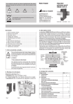
Bild 2
1 Operating Instructions (2) each in German, French and English
1 Type Examination Certificate (3), (only for “intrinsically safe”
explosion-proof devices)
3. Brief description
1. Read first and then …
The proper and safe operation of the device assumes
that the Operating Instructions are read and the safety
warnings given in the various Sections
6. Installation in the plant
7. Electrical connections
8. Configuring the transmitter
9. Commissioning
are observed.
The device should only be handled by appropriately trained personnel who are familiar with it and authorised to work in electrical
installations.
Unauthorized repair or alteration of the unit invalidates the
warranty!
2. Scope of supply (Figs. 1 and 2)
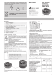
Transmitter, one of the two versions (1)
Order Code: Significance of the 2nd. and 3rd. digits
616 – 7 x x
↑ ↑
1
Standard, not electrically isolated
2
Standard, electrically isolated
3
EEx ia IIC T6, not electrically isolated
4
EEx ia IIC T6, electrically isolated
0 Basic configuration programmed
1 Configured to order
(1)
Fig. 1
The programmable SINEAX VK 616 is a two-wire head-mounted transmitter. It is designed for installation in the terminal head of a temperature
sensor DIN 43 729, shape B.
It is used for measuring temperature in conjunction with a thermocouple
or resistance thermometer. Thermocouple non-linearities are automatically
compensated. The output signal is a current in the range 4…20 mA.
The input, measuring range, signalling and other parameters are programmed with the aid of a PC and the corresponding software.
The sensor circuit is monitored for open and short-circuits and the output
responds in a defined manner if one is detected.
The power supply of 12…30 V DC is connected together with the signal by
the two leads connected to the measurement output (loop powered).
Explosion-proof “intrinsically safe” EEx ia IIC T6 versions rounds off the
series of transmitters.
Transmitters supplied as standard versions are configured as follows:
–
–
–
–
–
Measuring input:
Measuring range:
Measuring output:
Open-circuit supervision:
Mains ripple suppression:
Pt 100 for three-wire connection
0 … 600 °C
4 … 20 mA
Output 21.6 mA
For frequency 50 Hz
4. Technical data
Measuring input
Input variable and measuring range configured
Input variables
Temperatures with resistance
thermometers for two, three or
four-wire connection
Pt 100, IEC 60 751
Ni 100, DIN 43 760
Temperatures with
thermocouples
Type B, E, J, K, N, R, S, T
acc. to IEC 60 584-1
Type L and U, DIN 43 710
Type W5 Re/W26 Re,
Type W3 Re/W25 Re,
acc. to ASTM E 988-90
Measuring ranges
Min.
Max.
span
span
Limits
–200 to 850°C
– 60 to 250°C
50 K
50 K
850 K
250 K
acc. to type
2 mV
80 mV
1
Via cold junction thermostat
0…60 °C, configurable
Measuring output
Output signal IA:
Standard range:
(output/powering circuit)
Impressed DC current,
linear with temperature
4…20 mA, 2-wire technique
External resistance
(load):
Rext max.
=
[kΩ]
(2)
16.8
1
External:
(1)
1.2
Cold junction compensation
Internal:
Incorporated Pt 100 or
with Pt 100 connected to the terminals
Fig. 4.
SINEAX VK 616-71/73,
not electrically isolated.
Transmitter
1.2
Power supply [V] – 12 V
Max. output current [mA]
12.5
30.8
Load max. [�] with
20 mA output
900
600
0
10
12
36
24
6. Installation in the plant
30
Mount the thermometer transmitter according type (screwed, sliding
terminal screws, flange etc.) at the prescribed location.
Power supply [V]
Programming connector on the transmitter
Interface:
Serial interface
Make sure that the ambient temperature stays within the permissible limits:
Standard instruments: – 25 and + 80 °C
Ex version:
– 25 to max. 57 °C (depending on Pi,
see type examination certificate)!
Open and short-circuit sensor circuit supervision
Signalling modes:
Output signal configurable to…
… the value the output had immediately prior
to the opern or short-circuit* (hold value)
… a value between 4 and 21.6 mA
* The short-circuit indicator is only active for
the RTD ≥ 100 Ω at 0 °C, three and four-wire
measuring mode
Power supply
DC voltage:
Fig. 5.
SINEAX VK 616-72/74,
electrically isolated.
Fig. 3. Spring mounting on
the insert in the terminal head.
7. Electrical connections
The leads are connected to the 6 Philips head screw terminals on the
front of the transmitter. The maximum wire gauge is 2 x 1.5 mm2, (see
Fig. 6). The applicable enclosure Protection Class for the terminals is
IP 00 according to EN 60 529.
Supply 12 … 30 V DC
max. residual ripple 1% p.p.
(supply must not fall below 12 V)
Protected against wrong polarity
1
4
2
3
Fig. 6
5. Securing the terminal head of the
temperature sensor
Also note that, ...
... the data required to carry out the prescribed measurement must correspond to those marked on the nameplate
of SINEAX VK 616 (Sensor, Range, Output, Supply Voltage)
(see Fig. 8)!
... the total loop resistance connected to the output (receiver plus
leads) does not exceed the maximum permissible value Rext., see
“Measuring output” in Section “4. Technical data”!
… the measurement input and output cables should be twisted pairs
and run as far as possible away from heavy current cables!
In all other respects, observe all local regulations when selecting the
type of electrical cable and installing them!
The SINEAX VK 616 is suitable for mounting on an insert that is fitted
into a temperature sensor with a Shape B DIN terminal head.
The length of the leads to the insert has to conform to the height of the
particular terminal head (Figures 4 and 5).
Thread the leads through the hole in the centre of the transmitter. Align
the transmitter in the lower part of the terminal head and secure it using
two chease-headed screws (1) and two springs (2) (see Fig. 3). Connect
the leads acc. to section “7. Electrical connections”.
In the case of “Intrinsically safe” explosion-proof, the
supplementary information given on the type examination
certification, the EN 60 079-14, and also local regulations
applicable to electrical installation in explosion hazard
areas must be taken into account!
7.1 Alternative measurement connections
Connect the measuring leads to suit the application as given in
Table 1.
Table 1: Measuring input
4
4
3
3
2
2
2
2
2
1
1
1
1
1
RTD
Four-wire
connection
RTD
Three-wire
connection
TC
Internal cold
junction
compensation
with incorporated Pt100
3
ϑ
TC
Internal cold
junction
compensation
with Pt100
connected to
the terminals
TC
External cold
junction
compensation
4
4
3
ϑ
2
4
4
3
ϑ
Rw1
3
ϑ
Rw2
2
1
RTD
Two-wire
connection
3
2
4
1
8. Configuring the transmitter
Notes:
7.1.1 Connection to thermocouples
Pay attention to correct polarity when connecting thermocouples. If the
lead from the thermocouple to the transmitter has to be extended, be
sure to use thermally compensated leads suitable for the particular type
of thermocouple.
The transmitter is configured via the serial interface of a PC. For the
configuration, a special advantage is that devices of both the standard
and Ex executions, with and without a separate power supply connection
can be configured.
The following accessories are required:
… PC software V 600 plus
7.1.1.1 Internal cold junction compensation with incorporated Pt100
… Programming cablee PK 610
Connect terminals 1 and 4 when using internal compensation by
comparison.
… Ancillary cable for SINEAX Type VK 616
Set the configuration software to “internal thermo-element” and “Pt100
built-in”.
A PC with an RS 232 C interface (Windows 3.1x, 95, 98, NT or 2000)
is also required.
The configuration procedure and choice of parameters is explained by
the menu-guided configuration program.
7.1.1.2 Internal cold junction compensation with Pt100 connected to
the terminals
For this alternative, a Pt100 is connected to terminals 1 and 4 . Terminals 1 and 2 must be connected.
SINEAX VK 616
Set the configuration software to “internal thermo-element” and “Pt100
on terminals”.
Safe area
Ancillary cable
7.1.1.3 External cold junction compensation
When using a cold junction thermostat, please observe that the correct
reference temperature is configured. The connection between the cold
junction thermostat and the transducer is made with copper wires.
Interface
PK 610
Programming
connector
OFF
ON
7.1.2 Connection to resistance thermometers
OFF: Connect separate power
supply to SINEAX (Fig. 7)
ON: Power supply provided
by PC
7.1.2.1 Two-wire connection
Terminals 1 and 2 and 3 and 4 must be connected in the case
of a two-wire measurement.
The lead resistance must not be greater than 30 Ω per lead.
7.1.2.2 Three-wire connection
Terminals 1 and 2 must be connected in the case of a three-wire
measurement. It is not necessary to compensate the leads, providing
the three leads have identical resistances. The lead resistance must not
be greater than 30 Ω per lead.
Fig. 9. Configuring of SINEAX VK 616 without the power supply. For this
case the switch on the interface must be set to “ON”.
Hazardous area
7.1.2.3 Four-wire connection
Sensor
The four-wire measurement is independent of lead resistance within wide
limits and therefore no compensation is necessary. The lead resistance
must not be greater than 30 Ω per lead.
7.2 Measuring output leads (output/powering circuit)
Connect the measuring output leads (analog output and power supply)
to terminals
and
acc. to Fig. 7.
3
2
Sensor
VK 616
-73/-74
Safe area
VK 616
-73/-74
PK 610
PK 610
Fig. 10. Configuring the SINEAX VK 616, types 616-73/74 when the
transducer and/or the sensor are in the hazardous are.
Permissible power supply
12 … 30 V DC
4
1
Rext
Permissible load max. Rext
(acc. to power supply)
900 Ω at 30 V
600 Ω at 24 V
400 Ω at 20 V
Fig. 7
Note, that twisted leads must be used for the output signal.
Supply Sensor: Pt100
Voltage Range: 0...100°C
Type 616-7111 4100 000
Ord: 616 / 123456 / 123 / 001 12...30V Output: 4...20mA
VK 616
Fig. 8. Example of a nameplate.
Camille Bauer AG
Aargauerstr. 7
CH-5610 Wohlen
Switzerland
Depending on whether the device is programmed with or without a
separate power supply, the switch on the PK 610 interface is to be set
to “ON” or “OFF”. See Fig. 9.
The earthing conditions must be observed when programming the instrument, (e.g. the instrument is installed in the
plant).
If for the VK 616-72/-74 one of the input wires is earthed,
or for the VK 616-71/-73 one of the power supply or input
wires is earthed, a PC without an earth connection, must
be used when programming (e.g. a notebook running on
the batteries).
Under no circumstances should a PC be used running
from a power supply with an earth connection, as this will
damage the transducer.
3
12. Dimensional drawings
1
33
If the above voltage level is not supported (e.g. operation
from the mains power supply) the earth connection of
the programming cable PK 610 must be connected to
the potential equalization conductor. At the same time,
it must be ensured that the programming circuit of the
VK 616 is potential free.
Ø 5.7
Ø 4.3
Ø 43
For devices of the explosion protection type “intrinsically
safe”, the PC or laptop must support a voltage level of
500 Veff between the RS 232 interface and earth (e.g.
battery operation). In particular, check other peripheral
devices that are connected.
16.8
38.9
Fig. 11. Connect the
earth connection to the
PK 610 interface.
Fig. 12. Remove the
earth connection from
the PK 610 interface.
Fig. 13. SINEAX VK 616-71/73, not electrically isolated.
Ø 4.3
33
Ø 5.7
12.5
Ø 43
9. Commissioning
Switch on the measuring input and the power supply.
The ambient temperature must be between – 10 and
+ 80 °C for standard instruments and – 10 and max.
57 °C for Ex versions (depending on Pi, see type examination certificate).
1.2
30.8
38.9
Fig. 14. SINEAX VK 616-72/74, electrically isolated.
10. Maintenance
No maintenance is required.
13. Declaration of conformity
EG - KONFORMITÄTSERKLÄRUNG
DECLARATION OF CONFORMITY
11. Accessories and spare parts
Order No.
Description
Programming cable PK 610
Interface
DSUB 9p F
137 887
Dokument-Nr./
Document.No.:
VK616 GT.DOC
Hersteller/
Manufacturer:
Camille Bauer AG
Switzerland
Anschrift /
Address:
Aargauerstrasse 7
CH-5610 Wohlen
Produktbezeichnung/
Programmierbarer Temperatur-Messumformer
mit galvanischer Trennung
Programmable temperatur transmitter
Input/output electrically isolated
SINEAX VK616
Product name:
Typ / Type:
Das bezeichnete Produkt stimmt mit den Vorschriften folgender Europäischer Richtlinien überein,
nachgewiesen durch die Einhaltung folgender Normen:
1 meter
The above mentioned product has been manufactured according to the regulations of the following
European directives proven through compliance with the following standards:
Ancillary cable SINEAX type VK 616
141 440
1.5 meter
PC software V600 plus on CD
(Download free of charge under
http://www.camillebauer.com)
146 557
Operating Instructions VK 616 Bd
in German
137 902
Operating Instructions VK 616 Bf
in French
142 076
Operating Instructions VK 616 Be
in English
142 125
Nr. / No.
89/336/EWG
89/336/EEC
Richtlinie / Directive
Elektromagnetische Verträglichkeit - EMV - Richtlinie
Electromagnetic compatibility -EMC directive
EMV /
EMC
Störaussendung /
Emission
Störfestigkeit /
Immunity
Fachgrundnorm /
Generic Standard
EN 50 081-2 : 1993
Messverfahren /
Measurement methods
EN 55011 : 1992
EN 50 082-2 : 1994
IEC
IEC
IEC
IEC
IEC
Nr. / No.
73/23/EWG
Richtlinie / Directive
Elektrische Betriebsmittel zur Verwendung innerhalb bestimmter Spannungs grenzen - Niederspannungsrichtlinie - CE-Kennzeichnung : 95
Electrical equipment for use within certain voltage limits - Low Voltage Direc tive - Attachment of CE mark : 95
73/23/EEC
EN/Norm/Standard
EN 61 010-1 : 1993
:
:
:
:
:
1991
1995
1988
1995
1995
IEC/Norm/Standard
IEC 1010-1 : 1990 + A1 : 1992
Die explosionsgeschützte Ausführung dieses Produkts stimmt mit der Europäischen
Richtlinie 94/9/EG überein.
The explosion protected variant of this product has been manufactured according the
European directive 94/9.
Ort, Datum /
Place, date:
4
1000-4-2
1000-4-3
1000-4-4
1000-4-5
1000-4-6
Wohlen, den 6. November 2000
Unterschrift /
Signature:
Leiter Entwicklung
M.Ulrich
Diese Erklärung bescheinigt die Übereinstimmung mit den
genannten Richtlinien, beinhaltet jedoch keine Zusicherung
v on E ige ns c h aften. Die Sic her heit s hinwe is e der m it gelief erten
Produktdokumentationen sind zu beachten.
T h i s d eclaration certifies compliance with the above mentioned
directives but does not include a property assurance.
The safety notes given in the product documentations, which are
part of the supply, must be observed.
1.8