1
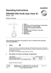
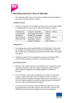
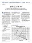
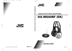
BA46E031
Operating Instructions
ERHARD ERU Knife Gate Valve K1
DN 50 - 300
Handwheel, chain wheel, types of operation by square end
1
2
3
4
5
6
7
8
Description of Product and Range of Application
Design Features – Technical Data
Performance and Mode of Operation
Storage
Installation into the Pipeline – Mounting
Initial Operation
Operation and Application
Maintenance
These operating instructions must always be used in combination with operating
instructions BA01E001!
1
Description of Product and Range of Application
Type/Design
ERU Knife Gate Valve K1
ERU Knife Gate Valve K1 with regulating orifice
Product number
4655.... PN 10
4656.... PN 10
with non-rising stem,
designed for manual operation by handwheel, chain wheel or operating key,
for extension of the operating device, e.g. by means of extension stem.
Product No.
4655, 4656
4657, 4623
BA46E031
August 2003
Rev. 7
Nominal
Diameter
Nominal
Pressure
Hydr. test pressure in bars
for
DN
PN
Body
Seat
Max. admissible working
pressure in bars at a
working temperature of
max. 70° C
50 - 300
50 - 300
10
10
15
15
10
10
10
10
ERHARD-Armaturen x D-89502 Heidenheim x Postfach 1280
(07321) 320-0 (07321) 320 491 e-mail:[email protected]
Internet: http://www.erhard.de
Page 1 of 8
Operating Instructions for ERHARD ERU Knife Gate Valve K1 with operation by square end
If EPDM profile seals are used for the ERU Knife Gate Valve K1, the parts of EPDM
must not get in contact with oil or grease, as the EPDM would swell.
For a recommended lubricant see section "Maintenance".
ERU Knife Gate Valves K1 of this design are suitable for "ON-OFF" operation.
For explicit regulating service, special designs have to be used, e.g. design with
regulating orifice.
2
Design Features
Drawing 3E 65931
ERU Knife Gate Valve K1 with square end operating variants.
BA46E031
August 2003
Rev. 7
ERHARD-Armaturen x D-89502 Heidenheim x Postfach 1280
(07321) 320-0 (07321) 320 491 e-mail:[email protected]
Internet: http://www.erhard.de
Page 2 of 8
Operating Instructions for ERHARD ERU Knife Gate Valve K1 with operation by square end
Parts lists and sets of spare parts (for drawing 3E 65931)
1.
Replace profile seal
Set 1
2.
Replace U-shaped sealing element
Set 2
3.
Replace stem
Set 3
4.
Replace stem nut
Set 4
Item.
1
2
3
4
5
6
7
8
9
10
11
12
13
14
15
16
17
18
19
20
21
22
23
24
25
26
27
28
29
30
31
32
33
34
35
36
37
38
BA46E031
August 2003
Rev. 7
Description
Body component
U-Shaped sealing element
Hexagon bolt
Washer
Hexagon nut
Gate
Profil seal
Guide tape
Compressor
Cover plate
Washer
Hexagon bolt
Stud bolt
Stem nut
Washer
Hexagon bolt
Conic.lubr.nipple/Prot.cap
Gudgeon
Bearing plate
Stop ring
Stem
Distance washer
Gasket
Washer
Hexagon nut
Taper plug
Handwheel
Washer
Hexagon bolt
Square cap
Close-tolerance grooved pin
Square muff
Straight grooved pin
Chainwheel
Sealing element
Collar disc
Straight grooved pin
Hexagon bolt
Set1
Set2
every 2 years
every 5 years
if necessary
if necessary
Set3
Set4
X
X
X
X
X
X
X
ERHARD-Armaturen x D-89502 Heidenheim x Postfach 1280
(07321) 320-0 (07321) 320 491 e-mail:[email protected]
Internet: http://www.erhard.de
X
X
Page 3 of 8
Operating Instructions for ERHARD ERU Knife Gate Valve K1 with operation by square end
Dimensioned table (for drawing 3E 65931)
3
DN
D1
D2
D3
E1
E2
H1
H2
H3
H4
L
S
50
65
80
100
125
150
200
250
300
165
185
200
220
250
285
341
395
445
200
200
200
250
250
250
300
300
400
212
212
212
248
248
295
295
295
342
19,5
19,5
19,5
22
22
25,5
25,5
32
35
177
177
177
213
213
260
260
260
307
300
325
355
393
433
486
587
701
820
321
346
376
418
458
507
624
736
853
365
390
420
460
500
553
654
768
891
313
338
368
408
448
501
602
716
835
43
46
46
52
56
56
60
68
78
14
14
14
17
17
19
19
19
24
Performance and Mode of Operation
ERU Knife Gate Valves K1 are wafer-type single-door gate valves with short face-toface dimension. A special type of these valves, e.g. with regulating orifice, is also
suitable for regulating purposes. The solid gate slides in a long gate guide between
two body components. It seals on its periphery against a rubber-resilient, steelreinforced, enclosed U-shaped sealing element. Where the gate leaves the body,
tightness to the outside is ensured by a resiliently prestressed profile seal which can
be readjusted. For reducing wear and tear of the profile seal and the actuating
elements the prestress can be reduced to the dimension required for the actual
operating pressure.
The Gate Valves were tested for tightness and resistance to DIN EN 12266 and DIN
EN 1074 at the manufacturer's plant. They are designed for flow acting from any
direction.
4
Storage
Store ERU Knife Gate Valves K1 in their closed position. Rubber-coated components,
as e.g. the sealing element between the body parts, have to be protected against
direct solar radiation. Avoid the effects of radiant heat, e.g. from heaters.
BA46E031
August 2003
Rev. 7
ERHARD-Armaturen x D-89502 Heidenheim x Postfach 1280
(07321) 320-0 (07321) 320 491 e-mail:[email protected]
Internet: http://www.erhard.de
Page 4 of 8
Operating Instructions for ERHARD ERU Knife Gate Valve K1 with operation by square end
5
Installation into the Pipeline - Mounting
Remove all packing material from the valve. Prior to installation, check the pipeline for
impurities and foreign bodies and clean it if necessary.
+ There must be free access all around the valve for operation and
maintenance.
In case of flow media containing solid matters as e.g. sand etc. and installation into
horizontal pipelines the stem or the piston rod should not be installed with an
inclination of more than 30º towards the horizontal. Thus, free flushing of the travel
range of the gate is possible.
In case of deviating installation positions, especially with suspended stem or piston
rod, deposits around the gate have to be expected. This could lead to malfunctions
which increase maintenance work.
During installation of the valve, the distance between the pipe flanges should exceed
the valve face-to-face dimension by at least 20 mm. Thus, the raised faces will not be
damaged and the gaskets can be inserted. Steel-reinforced rubber seals to DIN 2690
are recommended for use as flange gaskets, for slip-on flanges they are absolutely
necessary (consider resistance to flow medium and temperature).
The mating pipe flanges must be plain-parallel and concentric.
Tighten the connecting bolts evenly (without distortion) and crosswise. The pipeline
mustn't by any means be pulled up to the valve.
If the distance between the flanges is too large for the valve, use thicker gaskets to
cover the difference.
ERU Knife Gate Valves K1 are
- clamped between two flanges of the pipeline (wafer type) or
- screwed to the end flange of the pipeline as end-of-line valves.
The screwed connection with the pipeline is made from flange to flange by means of
bolts in the through-going holes. For the threaded blind holes the screwed connection
is made by means of stud bolts or bolts in the body components.
It is possible to roughly fasten the valve by means of the threaded holes.
The necessary connecting elements for the corresponding installation position are
shown in drawing No. 4E127 920.
BA46E031
August 2003
Rev. 7
ERHARD-Armaturen x D-89502 Heidenheim x Postfach 1280
(07321) 320-0 (07321) 320 491 e-mail:[email protected]
Internet: http://www.erhard.de
Page 5 of 8
Operating Instructions for ERHARD ERU Knife Gate Valve K1 with operation by square end
Connecting elements for flange connection; drawing: 4E127920
BA46E031
August 2003
Rev. 7
ERHARD-Armaturen x D-89502 Heidenheim x Postfach 1280
(07321) 320-0 (07321) 320 491 e-mail:[email protected]
Internet: http://www.erhard.de
Page 6 of 8
Operating Instructions for ERHARD ERU Knife Gate Valve K1 with operation by square end
6
Initial Operation
Note: Before start-up spindle and spindle nut are to be greased.
(recommended lubricant see section “Maintenance”)
After installation, the valve has to be checked for smooth operation.
It has to be moved at the operating element over the whole travel (OPEN-CLOSED).
When the gate – being opened - gets in contact with the bearing plate, the valve is in
open position. The profile seal is adjusted (pretensioned) to nominal pressure at the
manufacturer's factory. In case of lower working pressures, after having carried out the
pressure test of the pipeline, the profile seal can be released to be adapted to the
effective working pressure. For
this purpose, the bolts on the cover plate have to be loosened in an appropriate
manner. By means of this measure you can reduce wear and tear of the components
involved in the motion.
ATTENTION! The flow medium may penetrate. Wear safety clothing (safety
goggles) in case of toxic or caustic media.
+ Extension of the operating elements, e.g. by lever or similar device, is not
allowed, as it might cause damages!
7
Operation
Trouble
Possible Causes
Remedy
Leakage at the
cover plate
Prestress too low
Readjustment of cover plate
see paragraph “8 Maintenance“
Wearing of the profile seal
Replace profile seal
Contamination
(deposit on the gate)
With valve in open position:
clean and grease gate
Contamination of the gate
With valve in open position:
clean and grease gate
Defective U-shaped sealing element
Replace sealing element
Contamination (deposit) on the gate
With valve in open position:
clean and grease gate
Stem running dry
Regrease thread
Residues of flow medium are
hardened
Relieve pipe section from pressure.
Clean and grease all accessible surfaces of
gate and stem.
Seat leakage
Excessive operating
forces
Operation blocked
BA46E031
August 2003
Rev. 7
ERHARD-Armaturen x D-89502 Heidenheim x Postfach 1280
(07321) 320-0 (07321) 320 491 e-mail:[email protected]
Internet: http://www.erhard.de
Page 7 of 8
Operating Instructions for ERHARD ERU Knife Gate Valve K1 with operation by square end
Slacken cover plate. Slightly unscrew upper
body bolts. Knock on the valve with a rubber
mallet trying to operate the valve. If you are not
successful: remove, dismantle, clean, replace
damaged parts.
Foreign bodies jammed in the
seating zone
8
Move valve in OPEN position and repeat
closing procedure
Maintenance
For inspection or repair, the valve – or parts thereof - must not be removed unless the pipe
section in which the valve is installed has been isolated and made pressureless. If work is
carried out in the vicinity of the valves, which leads to soiling (concrete work, masonry,
painting, sandblasting and the like), the valves must be covered effectively.
ERU Knife Gate Valves K1 have to be moved regularly at short intervals (every half years)
over the whole travel (OPEN-CLOSED). Depending on the flow medium and the local
conditions at the site of application, the maintenance interval must be reduced or may be
extended.
If the profile seal is found to be untight, retighten the hexagon bolts of the cover plate evenly.
If it is no longer possible to retighten the cover plate, replace the sealing elements.
Check gate and stem regularly for contaminations, clean them if necessary and treat them
with lubricant (rub in a thin layer).
Recommended lubricant:
KLÜBERSYNTH VR69-252
company Klüber Lubrication, Munich
Spare parts and wearing parts according to: drawing 3E 65931
BA46E031
August 2003
Rev. 7
ERHARD-Armaturen x D-89502 Heidenheim x Postfach 1280
(07321) 320-0 (07321) 320 491 e-mail:[email protected]
Internet: http://www.erhard.de
Page 8 of 8