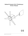
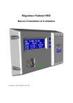
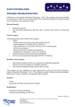
1
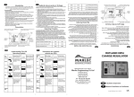
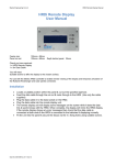
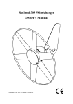
Spectraflex Installation & User Manual Thank you for purchasing this solar panel. To enjoy maximum satisfaction from the product we strongly recommend you read the following instructions! 1. 2. 3. 4. 5. Important Information This manual contains important installation and safety instructions – please read carefully and follow. Do not attempt to open the junction box attached to the panel. Do not drill additional holes in the panel. Spectraflex solar panels are flexible to allow fixing in temporary or permanent locations. E.g. deck, hatch cover, boom cover, caravan/motorhome awning or roof. They will fit contours of minimum 300mm dia (see Figure 1) but should not be curved beyond this as overbending will permanently damage the panel and invalidate the warranty! Do not fold or crease during transportation or storage. Always observe the correct polarity when making electrical connections. Only walk on the panel using soft soled shoes (e.g. deck shoes) and only when the panel is fully supported underneath by a solid surface. Mounting If making a permanent installation choose a location that is free from shade and South facing in the Northern hemisphere. For optimum performance tilt the panel at an angle of 15º plus the location’s latitude from horizontal. On a boat or caravan it is usually more practical to install it flat. Fix the panel with screws using the 6 fixing rings provided or use adhesive on the back to stick it in place. For a temporary installation it can be tied in position with rope. Do not drill extra holes in the panel as this will damage it and invalidate the warranty! Electrical Connection Spectra solar panels are suitable for use with sealed and non-sealed 12V lead acid batteries. To avoid short circuits and sparking cover the panel when making electrical connections. Connect the solar panel directly to the battery terminals or if necessary through a solar regulator. Use suitable battery clips fitted to the output cables (e.g. Marlec part no. 901-030). A diode is fitted inside the junction box to prevent the battery discharging back into the panel in darkness. Always observe the correct polarity (Red +VE/Black –VE)! (See Figure 2) If the distance from solar panel to battery (or regulator) exceeds the 3m of output cables then use cable of sufficient diameter to avoid unnecessary voltage drop. More than 1 panel may be used together in parallel to give higher output current but NOT in series to give higher voltage (e.g. 24V system). – see Figure 3. 10W of solar panels to each 100Ah of battery is recommended to replace natural discharge levels based on latitude of 50°N. A solar regulator is recommended for higher ratios and at locations closer to the equator. Maintenance Occasionally wipe the solar panel with a damp cloth (use only water and mild detergent) to remove the build –up of dirt, salt etc. Non-sealed batteries should be maintained in accordance with manufacturer’s instructions. All wiring and connections should be checked for integrity and corrosion at least annually. Warranty Spectra solar panels carry a 2 year warranty providing free replacement cover for all defects in parts and workmanship from date of purchase. A valid proof of purchase will be required if making a warranty claim. Defective products must be returned by prepaid post to your dealer or to Marlec Engineering Co Ltd, Trevithick Road, Corby, Northants, NN17 5XY, UK. This Warranty is void in the event of improper installation, modification, owner neglect, misuse or damage caused by natural disasters and does not extend to batteries, inverters or other ancillary equipment. No responsibility is assumed for incidental or consequential damage or damage caused by the use of unauthorised components. Your statutory rights are not affected. Specifications are subject to change without notice. Doc No: SM-223 Issue A 09.10.08 Marlec Eng Co Ltd Figure 1 Min 300mm dia Figure 2 Solar Panel -VE (Black) +VE(Red) Output to Battery (or regulator) Figure 3 -VE +VE -VE -VE(Black) +VE +VE(Red) 12V Parallel Connection www.marlec.co.uk Doc No: SM-223 Issue A 09.10.08 Marlec Eng Co Ltd