1
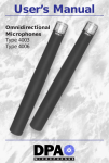
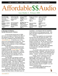
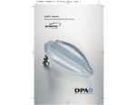
User’s Manual
DPA D3 Decca Tree
DPA D3c Decca Tree
with Integrated Cables
DPA S5 Surround Mount
DPA S5c Surround Mount
with Integrated Cables
Contents
Product overview.......................................................................................................................................2
General description................................................................................................................................3
Center Disc..........................................................................................................................................................3
Suspension Hooks..................................................................................................................................4
Measuring Tape and Protractor..........................................................................................4
Horizontal adjustment/angle between microphone pairs.......... 5
Vertical adjustment/tilt........................................................................................................................6
Integrated cable option (included in D3c and S5c).........................7
For use as an AB stereo boom.........................................................................................8
For use as D3 Decca Tree..........................................................................................................9
For use as S5 Surround Mount.....................................................................................17
Specifications.................................................................................................................................................33
Environmental Policy.........................................................................................................................35
Service & Repair.......................................................................................................................................35
Other microphone groups.....................................................................................................36
Product overview of assembling components
Ref.
2
Type no.
Product
D3
D3c
S5
S5c
A
CD5000
Center Disc
(w. thread adapter)
1 pc.
1 pc.
1 pc.
1 pc.
B
TBH5000
Telescopic Boom with Microphone
Holders
3 pcs.
3 pcs.
5 pcs.
5 pcs.
C
SEU5000
Short Extension Unit
6 pcs.
6 pcs.
8 pcs.
8 pcs.
D
LEU5000
Long Extension Unit
3 pcs.
3 pcs.
9 pcs.
9 pcs.
E
DAO3000
& DAO5000
Balanced Mic Cable Female XLR
- Lemo/Male XLR Adapter, 10 m (33 ft)
-
3 pcs.
-
5 pcs.
F
RCD5000
Rear Center Disc
-
-
1 pc.
1 pc.
G
TEU5000
Telescopic Extension Unit
-
-
1 pc.
1 pc.
H
MT5000
Measuring Tape
1 pc.
1 pc.
1 pc.
1 pc.
I
PMH5000
Protractor
1 pc.
1 pc.
1 pc.
1 pc.
J
SH5000
Suspension Hook
3 pcs.
3 pcs.
5 pcs.
5 pcs.
General description
The DPA Decca Tree (D3) and Surround Mount (S5) are highly versatile and
stylish microphone mounts for two to five microphones. The unique building
block design of the D3 and S5 mounts provides extreme flexibility, allowing for
numerous configurations while an integrated custom length cable option adds
even more value to the product’s visual elegance.
In the concert hall, the mount is hardly visible and completely non-light reflective.
The mount is equally suitable for fixed installations and mobile setups and can be
neatly packed away into the supplied briefcase for easy transportation. Compact
and extremely lightweight, the DPA mount is very strong and stable.
Although the array is optimized for use with DPA microphones, it accommodates
all microphone holders due to its standard 5/8” thread, and a broad variety
of surround microphone arrays can be set up very neatly. In the Decca Tree
configuration, all three microphones can be spaced 60 to 210 cm (2 to 7 ft) apart,
either aligned, in a vintage Decca school T-shape, or in an equilateral triangle
configuration for optimal balance with a centered fixation point.
Center Disc
The Center Disc has mounting information inscribed on both sides. Nevertheless,
always mount the Center Disc with the opening of the disc downwards for cable
outlet.
3
Suspension Hooks
Press the “eyes” on the spring together with two fingers and draw the open hook
over the Telescopic Boom to the dedicated hook mounting catch. Turn the hook
to the desired point and secure it by releasing the spring back to its original state.
The wires to the Suspension Hooks should be as vertical as possible. Avoid any
bending force to the microphone arms applied by the suspension wires.
Draw the open hooks over the Telescopic Booms
Release the spring at the desired point
Measuring Tape and Protractor
In order to keep the simple and elegant look of the microphone mount, there
are no distance or angle markings on the product (besides the three markings on
the Telescopic Booms). Please refer to the descriptions in this manual regarding
microphone array spacings or use the enclosed measuring tape to confirm your
desired microphone distances. The unique 3D protractor can be mounted on
each of the supplied microphone holders to adjust the microphone angle, both
horizontally (outer row) and vertically (inner row).
Measuring tape
Protractor for shock mount
When mounting mics in the shock mount, please note that there is a specially
designed protractor for this (supplied with the surround microphone kits).
4
Horizontal adjustment/angle between microphone pairs
Protractor mounted for
horizontal adjustment
Click the protractor on to the cylindrical microphone holder on the Telescopic
Boom. The screw on the microphone holder should be visible through the small,
round eye in the middle of the protractor. When angling the microphone, the
boom will now act as a pointer to the outer row showing the angle difference
between the L-C or R-C microphone (when using any forward pointing L and R
microphone boom configuration).
Two parallel pointing microphones should therefore read out 00 when using
forward pointing microphone boom configurations. When measuring the angle
between the LS and RS microphones, the protractor reads out the angle to an
imagined center line.
C
L
R
LS
RS
5
Vertical adjustment/tilt
The microphone can be angled up- or downwards, a vertical angle read will make
it easy to find the desired inclination:
Click the protractor on to the cylindrical microphone holder on the Telescopic
Boom.
The bullet will read out any angle offset at the inner row incorporated by either a
twist from the specific microphone arm or by the entire mount.
Protractor mounted for vertical adjustment
6
Integrated cable option (included in D3c and S5c)
Disassemble the XLR connection adapter at the male end of the cable.
Put the small Lemo connector into the opening by the microphone holder and
push the cable gently through the pipes to the center disc. Then plug the small
Lemo connector into the XLR connection adapter.
7
For use as an AB stereo boom
Use the Telescopic Extension Unit as a stereo boom and mount a microphone
holder at each end. Attach a third Microphone Holder on the thin tube part of
the Telescopic Extension Unit to make it mountable to a microphone stand. The
microphone basis can be adjusted from approx. 40 to 60 cm (16 to 24 in). The
integrated microphone cables from D3c or S5c can be drawn internally in the
boom and to the holder.
8
For use as D3 Decca Tree (three microphone array)
For best balancing of the microphone array, the D3 is designed so that the three
microphone booms can be mounted at the L, C, and R markings on the “Decca
Tree” side of the Center Disc. This offers a 120° angle between the booms and it is
possible (but not required) to have the microphones in an equilateral triangle, i.e.
equal distance between all three microphones.
Use the Telescopic Booms with microphone holders to change the microphone
distance. Each mark on the Telescopic Boom indicates 10 cm (4 in) increments in
microphone spacing when extending all three booms.
Depending on recording angle (determined by size and distance to the sound
source), spacing between microphones should be adjusted properly.
In the following, a few recommendable solutions for different venues and recording
angles are presented.
If you want to know more about recording techniques, please consult our Microphone
University at www.dpamicrophones.com.
9
Decca solution 1
If placement of the three microphones is desired to be in front of the conductor—and
the microphone stand behind—mounting the microphones in L, C, and R marks
on the “Surround” side of the Center Disc could be a solution. If using long booms,
a counter weight mounted on an extension unit in the “LS RS” marked hole is
recommended for better balance.
For better control of long booms in a large array, always start from the Center Disc
mounting the Extension Units before the Telescopic Booms. When dismounting, start
from the outside with the microphones, then the booms and extension units.
For microphone spacing from 120 to 150 cm (4 to 5 ft) for the microphones to
be aligned:
1 x A Center Disc
3 x B Telescopic Booms with microphone holders
2 x D Long Extension Units
120-150
cm
120 – 150 cm
B
B
B
D
D
A
10
Decca solution 2
For microphone spacing from 60 to 90 cm (2 to 3 ft) in an equilateral triangle:
1 x A Center Disc
3 x B Telescopic Booms with Microphone Holders
60 – 90
cm
B
A
B
B
60 – 90
cm
Each mark on the Telescopic Boom indicates 10 cm (4 in) increments in
microphone spacing when extending all three booms.
11
Decca solution 3
For microphone spacing from 90 to 120 cm (3 to 4 ft) in an equilateral triangle:
1 x A Center Disc
3 x B Telescopic Booms with Microphone Holders
3 x C Short Extension Units
B
C
C
C
A
B
B
90 – 120
cm
Each mark on the Telescopic Boom indicates 10 cm (4 in) increments in
microphone spacing when extending all three booms.
12
Decca solution 4
For microphone spacing from 120 – 150 cm (4 to 5 ft) in an equilateral triangle:
1 x A Center Disc
3 x B Telescopic Booms with Microphone Holders
3 x D Long Extension Units
B
120 – 150 cm
D
A
D
D
B
B
120 – 150
cm
Each mark on the Telescopic Boom indicates 10 cm (4 in) increments in
microphone spacing when extending all three booms.
13
Decca solution 5
For microphone spacing from 150 to 180 cm (5 to 6 ft) in an equilateral
triangle:
1 x A Center Disc
3 x B Telescopic Booms with Microphone Holders
3 x C Short Extension Units
3 x D Long Extension Units
B
D
C
C
A
C
D
D
B
B
150 – 180 cm
Each mark on the Telescopic Boom indicates 10 cm (4 in) increments in
microphone spacing when extending all three booms.
14
Decca solution 6
For microphone spacing from 180 to 210 cm (6 to 7 ft) in an equilateral
triangle:
1 x A Center Disc
3 x B Telescopic Booms with Microphone Holders
6 x C Short Extension Units
3 x D Long Extension Units
B
D
C
C
C
C
A
C
C
D
D
B
B
180 – 210 cm
Each mark on the Telescopic Boom indicates 10 cm (4 in) increments in
microphone spacing when extending all three booms.
15
Decca solution 7
For a Vintage Decca setup in a T-shape with 2 m (6.6 ft) between Left and Right
microphones and 1 m (3.3 ft) between the Center microphone and the LR basis:
1 x A Center Disc
3 x B Telescopic Booms with Microphone Holders
4 x C Short Extension Units (only for Left and Right)
2 x D Long Extension Units (only for Left and Right)
B
C
C
A
100 cm
C
C
D
D
B
B
200 cm
Each mark on the Telescopic Boom indicates 10 cm (4 in) increments in
microphone spacing, when extending all three booms.
16
For use as S5 Surround Mount
(five microphone array)
The possibilities with the S5 are numerous due to the extreme flexibility of the S5
kit. All microphone spacings from 60 to 200 cm (2 to 7 ft) are possible between
all five microphones, with a variable front-to-rear distance from 60 to 250 cm
(2 to 8.2 ft) depending on the boom lengths.
In the following, a few recommendable solutions for different venues and recording
angles are presented. Please note that some arrays are heavy and should only be
used as a suspended setup with the Suspension Hook solution.
If you want to know more about recording techniques, please consult our Microphone
University at www.dpamicrophones.com.
17
Surround solution 1
Portable Surround Array:
1 x A Center Disc
5 x B Telescopic Booms with Microphone Holders
1 x F Rear Center Disc
1 x G Telescopic Extension Unit
B
B
B
A
G
B
60
– cm
90
60-90
cm
18
F
B
Attach an optional Microphone Holder (UA0962) to the Telescopic Extension Unit.
This will make it possible to mount a number of Extension Units as an array boom
pole. Only use this solution if the array is not too big, since the angling option
will not hold too much bending force.
19
Surround solution 2
60 – 90 cm (2 – 3 ft) spacing between L-C-R and LS-RS
1 x A Center Disc
5 x B Telescopic Booms with Microphone Holders
1 x C Short Extension Unit (for 90 cm center boom)
1 x D Long Extension Unit
1 x F Rear Center Disc
1 x G Telescopic Extension Unit
60 – 90
cm
B
D
B
B
A
G
B
F
B
60 – 90
cm
Optional: More extension units can be added to the Telescopic Extension Unit to
obtain desired distance between front and rear microphones.
20
Surround solution 3
90 – 120 cm (3 – 4 ft) spacing between L-C-R and LS-RS
1 x A Center Disc
5 x B Telescopic Booms with Microphone Holders
4 x C Short Extension Units
1 x C Short Extension Unit (for 120 cm on center boom)
1 x F Rear Center Disc
1 x G Telescopic Extension Unit
B
90 – 120
cm
D
D
B
B
C
A
C
G
C
C
F
B
B
90 – 120
cm
Optional: More extension units can be added to the Telescopic Extension Unit to
obtain desired distance between front and rear microphones.
21
Surround solution 4
120 – 150 cm (4 – 5 ft) spacing between L-C-R and LS-RS
1 x A Center Disc
5 x B Telescopic Booms with Microphone Holders
1 x C Short Extension Unit (for 150 cm on center boom)
7 x D Long Extension Units
1 x F Rear Center Disc
1 x G Telescopic Extension Unit
B
120 – 150
cm
D
D
B
B
D
D
D
A
G
D
F
B
D
B
120 – 150
cm
Optional: More extension units can be added to the Telescopic Extension Unit
to obtain desired distance between front and rear microphones.
22
Surround solution 5
150 – 180 cm (5 – 6 ft) spacing between L-C-R and LS-RS
1 x A Center Disc
5 x B Telescopic Booms with Microphone Holders
4 x C Short Extension Units
1 x C Short Extension Unit (for 180 cm on center boom)
8 x D Long Extension Units
1 x F Rear Center Disc
1 x G Telescopic Extension Unit
B
D
D
D
B
B
D
D
D
C
A
C
G
C
D
C
F
B
D
B
150 – 180 cm
Optional: More extension units can be added to the Telescopic Extension Unit to
obtain desired distance between front and rear microphones.
23
Surround solution 6
180 – 200 cm (6 – 7 ft) spacing between L-C-R and LS-RS
1 x A Center Disc
5 x B Telescopic Booms with Microphone Holders
8 x C Short Extension Units
9 x D Long Extension Units
1 x F Rear Center Disc
1 x G Telescopic Extension Unit
B
D
180 – 200
cm
D
D
D
B
B
D
D
D
C
C
C
A C
G
C
D
B
C
C
F
C
D
B
180 – 200
cm
Optional: More extension units can be added to the Telescopic Extension Unit to
obtain desired distance between front and rear microphones.
24
Surround solution 7
Large Decca Tree Front, Largely Spaced Cardioids Rear (5006-11 Surround
Microphone Kit).
Spacing between L-C-R: 200 cm (6.6 ft)
Spacing between LS-RS: 200 cm (6.6 ft)
Spacing between LR-LSRS: 150 cm (4.9 ft)
1
5
8
9
1
1
x
x
x
x
x
x
A
B
C
D
F
G
Center Disc
Telescopic Booms with Microphone Holders
Short Extension Units
Long Extension Units
Rear Center Disc
Telescopic Extension Unit
B
D
200 cm
200
cm
D
D
D
B
B
D
D
C
150 cmcm
150
C
D
C
A C
G
C
C
F
B
D
C
C
D
B
200 cmcm
200
Use the DPA 5006-11 Surround Microphone Kit to make a configuration with
matched 4006-TL omnis in the front and backwards faced 4011-TL cardioids for
the rear channels. Consider using the L50B Acoustic Pressure Equalizers for the
distinctive vintage Decca sound character and angling the cardiods upwards for
more height information.
25
Surround solution 8
Five omnis with Small Decca Tree Front and spaced omnis far rear (5006
Surround Microphone Kit).
Spacing between L-C-R: 100 cm (3.3 ft)
Spacing between LS-RS: 100 cm (3.3 ft)
Spacing between LR-LSRS: 250 cm (8.2 ft)
1
5
4
6
1
1
x
x
x
x
x
x
A
B
C
D
F
G
Center Disc
Telescopic Booms with Microphone Holders
Short Extension Units
Long Extension Units
Rear Center Disc
Telescopic Extension Unit
250 cm
250 cm
100 cm
100 cm
B
B
100 cm
B
100 cm
C
F G
C
A
D
D
D
D
D
D
C
C
B
B
Use the 5006 4006-TL Surround Microphone Kit to make a configuration with
matched 4006-TL omnis—consider using the L50B Acoustic Pressure Equalizers
for the distinctive vintage Decca sound character.
An array of this size should only be used as a suspended setup with the
Suspension Hook solution. If using microphone stands, it is necessary to use two
stands—one on each center disc—to stabilize the long rear extension boom.
26
Surround solution 9
Five omnis with vintage T-shaped Decca Tree front and spaced omnis far rear (5006
Surround Microphone Kit).
Spacing between L-R: 200 cm (6.6 ft)
Spacing between LR-C: 100 cm (3.3 ft)
Spacing between LS-RS: 100 cm (3.3 ft)
Spacing between LR-LSRS: 250 cm (8.2 ft)
1
5
6
9
1
1
x
x
x
x
x
x
A
B
C
D
F
G
Center Disc
Telescopic Booms with Microphone Holders
Short Extension Units
Long Extension Units
Rear Center Disc
Telescopic Extension Unit
250 cm
100 cm
B
D
200 cm
B
C
C
100 cm
G
D
D
D
D
D
D
C
D
F
C
A
C
B
C
B
D
B
An array of this size should only be used as a suspended setup with the Suspension
Hook solution. If using microphone stands, it is necessary to use two stands—one
on each center disc—to stabilize the long rear extension boom.
27
Surround solution 10
Five wide cardioids (5015 Surround Microphone Kit) for use in the WCSA Wide
Cardioid Surround Array developed by Mikkel Nymand, DPA Microphones.
Spacing between L-C and R-C: 70 cm (2.3 ft)
Spacing between LR-C: 20 cm (0.7 ft)
Spacing between LS-RS: 150 cm (5 ft)
Spacing between LR-LSRS: 150 cm (5 ft)
1
5
1
5
1
1
x
x
x
x
x
x
A
B
C
D
F
G
Center Disc
Telescopic Booms with Microphone Holders
Short Extension Units
Long Extension Units
Rear Center Disc
Telescopic Extension Unit
60 – 75 cm
60 – 75 cm
20 cm
B
B
B
C
D
D
A
D
150 cm
G
D
F
B
B
120 – 150
cm
28
D
Surround solution 11
Five omnis, equidistant (5006 Surround Microphone Kit) for use in a Polyhymnia Array.
The microphones are spaced equally from a center point, the Center Disc.
Up to 160 cm (5.2 ft) distance from the center point is possible with the S5 kit.
1
5
8
9
1
1
x
x
x
x
x
x
A
B
C
D
F
G
Center Disc
Telescopic Booms with Microphone Holders
Short Extension Units
Long Extension Units
Rear Center Disc
Telescopic Extension Unit
B
D
D
B
B
D
D
C
D
160 cm
D
C
C
C
C
A C
D
G
160 cm
C
C
F
D
B
D
B
29
Other commonly used microphone arrays:
OCT (Optimized Cardioid Triangle) by Günther Theile
Spacing between LR: 60-90 cm (2-3 ft)
Spacing between C-LR: 40 cm (1,3 ft)
1 x A Center Disc
5 x B Telescopic Booms with Microphone Holders
2 x C Short Extension Units
1 x F Rear Center Disc
1 x G Telescopic Extension Unit
OCT 2
20 cm
B
OCT Surround
B
60-90 cm
60-90
cm
B
A
20-40 cm cm
20-40
B
60 – 90 cm
B
B
40 cm
A
40 cm
G
B
F
B
20 cm, max. 100 cm
LR+20LR + cm,
max 100 cm
For OCT surround an optional CD5000 is required
30
Hamasaki Square, by Kimio Hamasaki, NHK, Japan
1 x A Center Disc
4 x B Telescopic Booms with Microphone Holders
9 x D Long Extension Units
1 x F Rear Center Disc
1 x G Telescopic Extension Unit
180 – 200
cm
B
B
D
D
D
A
D
D
180 – 200
cm
180 – 200
cm
G
D
F
D
D
D
B
B
180 – 200
cm
31
Fukada Tree, by Akira Fukada, NHK, Japan
1 x A Center Disc
5 x B Telescopic Booms with Microphone Holders
7 x C Short Extension Units
9 x D Long Extension Units
1 x F Rear Center Disc
1 x G Telescopic Extension Unit
B
D
A
D
C
D
C
B
100 cm
D
B
C
C
100 cm
100 cm
C
C
D
200 cm
G
D
D
F
B
D
B
200 cm
32
D
Specifications
Color: Material: Weight w. microphone holders:
incl. briefcase:
D3
Black
Alu, steel
1,300 g(46 oz)
4,300 g(9.5 lbs)
S5
Black
Alu, steel
2,500 g (88 oz)
5,500 g (12 lbs)
Threads: 5/8”, Center Discs with thread adapters for 3/8”
Microphone spacings: Continuously variable 60 – 210 cm (2 – 7 ft)
Cables: Female XLR – Lemo/male XLR adapter. Length: 10 m (33 ft)
Custom lengths can be ordered
Maintenance
If the booms get dirty or lightly scratched, polish them with vaseline oil on a
lint-free cloth.
Accessories available
D3X
Upgrade Kit from D3 to S5
DAO3000
Three Cables and Adapters for D3, 10 m (33 ft)
DAO5000
Five Cables and Adapters for S5, 10 m (33 ft)
DAO5000-Y
Cable for Integration to D3/S5, 10 m (33 ft), L (yellow)
DAO5000-O Cable for Integration to D3/S5, 10 m (33 ft), C (orange)
DAO5000-R Cable for Integration to D3/S5, 10 m (33 ft), R (red)
DAO5000-B Cable for Integration to D3/S5, 10 m (33 ft), LS (blue)
DAO5000-G Cable for Integration to D3/S5, 10 m (33 ft), RS (green)
DAD5000
Lemo/male XLR adapter
CD5000
Center Disc
RCD5000
Rear Center Disc
TBH5000
Telescopic Boom with Microphone Holders
SEU5000
Short Extension Unit
LEU5000
Long Extension Unit
TEU5000
Telescopic Extension Unit
PMH5000
Protractor for Microphone Holder
PSM5000
Protractor for Shock Mount
SH5000
Suspension Hook
MT5000
Measuring Tape
UA0962
Microphone Holder for Integrated Cable in D3/S5
UA0898
Shock Mount for Integrated Cable in D3/S5
33
For use with:
5006 4006-TL Surround Microphone Kit:
5 x 4006-TL Omnidirectional Microphones, P48, Transformerless
5 x L50B Acoustic Pressure Equalizers, 50 mm (1.97 in) Ball
5006-11 4006-TL/4011-TL Surround Microphone Kit:
3 x 4006-TL Omnidirectional Microphones, P48, Transformerless
3 x L50B Acoustic Pressure Equalizers, 50 mm (1.97 in) Ball
2 x 4011-TL Cardioid Microphones, P48
2 x UA0898 Shock Mounts for Integrated Cable in D3/S5
5015 4015-TL Surround Microphone Kit:
5 x 4015-TL Wide Cardioid Microphones, P48
5 x UA0898 Shock Mounts for Integrated Cable in D3/S5
34
Environmental Policy
Service & Repair
DPA Microphones A/S is proud to be known
as a “green” company. It is company policy to
produce all products in accordance with the
best ecological practices to preserve the environment we are all a part of. Consequently, it
is DPA´s aim to cooperate with both national
and international legislative bodies to fulfil the
requirements and recommendations set out in
environmental standards and directives.
All products from DPA Microphones are
covered by a two-year limited warranty on
both mechanical functionality and documented specifications as long as the items
are not mistreated, abused, or modified in
any way. Invoices are required as warranty
registration documents in case of a claim.
Throughout DPA´s conduct and in its design
of new products, the company pursues solutions that have minimal impact on the ecology and are in line with the latest legislative
requirements (at present directive 9002/95/EC)
at the time a new product is introduced to the
market. These requirements are not only valid
for DPA but also its suppliers.
Find your nearest DPA representative on
our website, www.dpamicrophones.com,
or send e-mail to [email protected].
DPA Headquarters, Denmark:
Tel: + 45 4814 2828
Fax: + 45 4814 2700
DPA Inc., United States:
Tel: +1 303 485 1025
Fax: +1 303-485-6470
With respect to waste disposal, DPA fully
complies with the WEEE directive (9002/96/
EC) and will adhere to any amendments and
subsequent requirements. From 1 January
2006, all DPA products that require a return
for upgrading and/or reuse have been provided with a “waste” label. This means that at
the end of its usable life, the product may be
returned to the local DPA representative who
will return it to DPA for disposal under the
national legislation program. Furthermore, DPA
guarantees that any DPA product purchased
after 1 January 2000 will be covered by the
same program to ensure that end users have
adequate means to dispose of obsolete DPA
products.
© June 2007, DPA Microphones A/S - Product features and specifications are subject to change without notice.
35
Other microphone groups
DPA
are
Large
Diaphragm
top-of-the-range
one-inch
Microphones
capsule
omni
microphones. When choosing the right microphone for a particular application, it is important
to consider the diaphragm size. With their transparency and neutral character, DPA´s large diaphragm
microphones are ideal for use with vocals, strings,
or other acoustic instruments with a high dynamic
range.
DPA Standard Microphones are high quality studio
microphones comprised of omnis, cardioids, and wide
cardioids. Featuring stylish slim housing and distinctive
grid, these mics are designed for sonic integrity in
any venue. DPA´s audio philosophy is based on the
notion of zero sound coloration, and the complete and
honest accuracy of these microphones is unequalled.
DPA Compact Microphones are the smaller cousins
of the standard microphones and are also available
as omni, cardioid, and wide cardioid models. They
are especially valuable for low profile use together
with DPA´s elegantly designed stands, mounts, and
holders for the close-miking of instruments, as table
and podium mics, and as reinforcement mics in live
performance venues. The compact microphones combine the trademark DPA sound with aesthetic and
functional design solutions.
36
DPA
4090
Series
phones
for
studio
mance.
Discreet
are
instrument
recording
and
and
versatile,
micro-
live
perfor-
these
micro-
phones are characterized by a natural and open
sound. They are made specifically to suit the needs of
musicians as well as the rigors of the stage. The flat
frequency response of the 4090 and 4091 furthermore enable FOH engineers to use these microphones for sound system alignment.
DPA Hydrophone
offers
professional
recording
under extreme conditions. The DPA 8011 Hydrophone
is the only high-quality, 48 V Phantom-powered, underwater omnidirectional microphone in the world which
has been specially designed to handle high SPLs
and high static ambient pressure in fluids. It is the
optimum choice for professional sound recordings
under water, in extreme humidity, in gas-filled rooms,
or under other extreme conditions. Excellent for film
and sporting events.
Miniature
Microphones
and
Miniature
Microphone Headbands are perfect for theaters,
television, and close-miking instrument applications.
They have a neutral character with great detail and
resolution. Tailored to handle heat, humidity, and sweat
as well as wind and popping, the miniature mics are
completely undetectable and extremely rugged and
reliable on stage.
37
DPI-D3S5
Headquarters:
DPA Microphones A/S
Gydevang 42-44
DK-3450 Alleroed, Denmark
Tel:
+45 4814 2828
Fax: +45 4814 2700
[email protected]
www.dpamicrophones.com
United States:
DPA Microphones, Inc.
2432 N. Main St., Suite 200
Longmont, CO 80501, USA
Tel: +1 303-485-1025
Fax: +1 303-485-6470
[email protected]
www.dpamicrophones.com